|
|

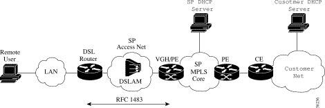
In a DSL solution, a session initiated by a client, through DSL equipment (CPE), as depicted in Figure 4-1 is:
1. Transmitted to a digital subscriber line access multiplexer (DSLAM) in the access provider network cloud
2. Distributed to an aggregation router within the same access provider network cloud where the PPP session is terminated and IP traffic is subsequently placed on one of the many tunnels that starts at the provider edge (PE) equipment in the service provider cloud
3. Tunneled through the access provider network cloud
4. Redistributed or delivered to the customer edge (CE) equipment as the final destination in the customer network cloud
Methods of DSL access (network environment architectures) covered in this Cisco VPN Dial Access to MPLS solution include:
These access methods are described in the following sections. Each section includes an overview of the architecture, a description of the solution components, and procedures for configuring the solution. Some configuration tasks can be expedited by using VPN Solution Center 2.1 templates. For details, see Using Templates for Configuration.
RFC 1483 DSL remote access routing provides connectivity between the Digital Subscriber Line (DSL) router and the Virtual Home Gateway/Provider Edge (VHG/PE). At the VHG/PE, the RFC 1483 interface is statically configured with a specific VRF (see Figure 4-2). Multiple IP subnets can be configured at the customer site and dynamic IP routing protocols can run between the DSL Router and the VHG/PE.
A Cisco DSL router is attached to a LAN connecting to a remote site's host PCs, and used as the customer premise equipment (CPE) to connect the remote access network to the SP DSL access network. The supported DSL routers are the Cisco 82x series, 14xx series, or SOHO77.
There is no remote user authorization and authentication with this RFC 1483 routing solution. Factors such as address assignment being DHCP-based, and accounting being Netflow-based make RFC 1483 routing more suitable for remote office, rather than residential user, connectivity to a MPLS VPN. See RFC 1483 Core Network for additional considerations.
IP routing protocols can be configured over the RFC 1483 PVC (permanent virtual circuit) which is useful when connecting remote offices with multiple subnets to the VPN.
The following VHG/PE platforms are used in Cisco VPN RFC 1483 remote access to MPLS.
The service provider access network is DSL with Cisco 6xx0 DSLAMs. RFC 1483 routing supports IP MPLS and ATM MPLS core networks.
DHCP (dynamic host configuration protocol) is used for address assignment through a Cisco Network Registrar (CNR) DHCP server for Cisco VPN RFC 1483 DSL access to MPLS.
The DHCP server assigns public and private addresses from a common service provider's address pool to all remote users regardless of the VPN they belong to. The DSL router and the VHG/PE interfaces must have IP addresses. Private addresses can be assigned from the service provider's private pool, if interfaces are reachable from other PE routers connected to the same VPN.
 |
Note The service provider DHCP server does not support overlapping addresses and is not VPN aware. |
The DHCP server can dynamically assigning addresses, to enable route summarization by assigning contiguous addresses to requests coming from the same DSL or VHG/PE router.
The following options exist for CPE address management.
|
Note The DSL router cannot relay the DHCP request to the DHCP server. It relays the request to the next hop, the VHG/PE routers, which relays it again to the DHCP server. |
Netflow is used for Cisco VPN RFC 1483 access to MPLS accounting. On the PE routers, Netflow is used to provide per flow usage accounting. The Netflow Collector provides Netflow usage data collection statistics such as time of first packets, time of last packet, number of packets, and number of octets used for performance reporting, capacity planning, and usage based billing. VPNSC collects the usage records from the Netflow Collector(s) and correlates them with the VPN service layer information.
A flow is identified by source address, source port, destination address, destination port, and more. When configured for Netflow accounting, the VHG/PE collects per flow accounting data and exports it to a Netflow Collector workstation, which stores it in flat files. A Netflow Analyzer is then used for analyzing the collected data.
Network management, fault monitoring, and SLA reporting are management functions performed in the core network.
Network management components for RFC 1483 consist of the following:
Fault monitoring is performed at the device, and service levels.
At the device level, fault monitoring is performed by the element managers (CEMF has an event manager component). CAM provides fault monitoring per dial port.
CIC is user at the service level to provide event correlation and filtering, monitoring, customer and administrative partitioning, and flow-through integration to other systems. CIC is an OEM product from Micromuse's NetCool. CIC's release 2.0 provides eventing at the IP VPN service level through integration with VPNSC.
SLA reporting is performed using the Service Assurance Agent (SA Agent) in IOS. At conventional MPLS VPN customer sites, VPNSC configures the SA Agent probes on managed CE routers, or shadow CE routers. At remote access sites, there is no real CE router so the SA Agent probes are configured on the PE routers at the PoPs. It is not possible to configure them on the NASs, because a NAS is not connected to a specific VPN so the probes are not routed using the VRFs. VPNSC collects statistics from the SA Agent MIB, and provides reports on a per VPN basis. For PPP users, performance numbers are derived from AR. For RFC 1483, the SA Agent probes are configured on the DSL routers at the CPE.
Performance and SLA reporting can be provided at a VPN service level through integration with VPNSC. RPMS is used to provide SLA information regarding incoming call rates per VPN customer.
Provisioning Cisco VPN RFC 1483 DSL access to MPLS entails:
1. Initial non-VPN services configurations performed through router pre-staging using config Xpress, an element manager (for example, SCM), CIPM templates, or any combination of these tools that include:
2. Customer and service configurations that include:
a. configuring the CNR servers
b. configuring the RFC 1483 PVCs on PE routers, using VPNSC 2
c. configuring the PE router for a new service by adding the required VRF configuration and DHCP helper addresses, using VPNSC 2
|
Note The DCHP helper address is only required for DHCP relay from the CPE device. |
3. VPN service configurations that include:
a. actual service activation performed by VPNSC where a VPN is created and CE sites and remote access sites are added to it.
|
Note For VPNSC configuration, refer to the MPLS VPNSC documentation suite at http://www.cisco.com/univercd/cc/td/doc/product/rtrmgmt/index.htm. |
Perform the following steps to configure the VHG/PE.
|
Note On the Cisco 6400, you can use SCM to perform configuration. |
|
Note Commands in a and b create a general loopback interface used for reachability to the router and are used as a source IP address for sessions (IBGP, TDP, etc.). |
c. Router (config-if)# interface loopback [number]
|
Note Commands c, d, and e create a loopback interface in a VRF necessary only if you use ip unnumbered interfaces to the CE device when you would ip unnumber the interface to this loopback. These steps are repeated for each customer VRF you ip unnumber interfaces to. |
Step 2 Define PVCs.
a. Router (config)# interface ATM[interface]/[interface]/[interface].[number] point-to-point (for the Cisco 6400). For example, interface ATM0/0/0.1 point-to-point
Router (config)# interface ATM[slot]/[port].[number] point-to-point (for the Cisco 7200). For example, interface ATM0/0.1 point-to-point
Router (config)# interface Switch [switchnumber].[number] point-to-point (for the Cisco MGX 8850 RPM-PR). For example, interface Switch 1.1 point-to-point
b. Router (config-if)# ip unnumbered Loopback [number]
Step 3 Use the following global command to configure label switching on the interface connected to the MPLS cloud:
For connecting to a MPLS cloud using MPLS ATM tagging, use the following commands:
a. Router (config-if)# interface ATM0/0/0.[number] mpls
b. Router (config-if)# ip address [ip address]
For frame-based tagging, the equivalent commands would be:
Step 4 Configure the VRF for each VPN.
a. Router (config)# ip vrf [vpn name]
b. Router (config-vrf)# rd [route descriptor]
c. Router (config-vrf)# route-target export [route target communities]
d. Router (config-vrf)# route-target import [route target communities]
Step 5 Configure a dedicated PVC for each VPN (PTA-MD).
a. Router (config)# interface ATM0/0/0.[number] point-to-point
b. Router (config-if)# ip vrf forwarding [vpn name]
c. Router (config-if)# ip address [ip address]
Step 6 Configure BGP to advertise the networks for each VPN.
a. Router (config)# router bgp [autonomous system number of sp]
b. Router (config-router)# neighbor [ip address of remote pe] remote-as [same autonomous number]
c. Router (config-router)# neighbor [ip address of remote pe] update-source Loopback0
d. Router (config-router)# address-family vpnv4
e. Router (config-router-af)# neighbor [ip address of remote pe] activate
f. Router (config-router-af)# neighbor [ip address of remote pe] send-community extended
Step 7 If using static routes, define them and redistribute them into BGP.
Perform the following step to configure the DSLAMS using CDM.
For Cisco DSL Manager (CDM) configuration details, refer to
http://www.cisco.com/univercd/cc/td/doc/product/rtrmgmt/cdm/cdm33/index.htm
A Cisco 82x series, 14xx series, or SOHO77 router is configured to forward DHCP requests unaltered to the VHG/PE for DHCP relay. If the VHG/PE interface is a numbered interface with the ip-helper command configured, the GIADDR field of the DHCP discover packet is set to the IP address of the VHG/PE interface. This allows the DHCP scope to be provisioned on the CNR server accordingly.
If the VHG/PE interface is unnumbered to a loopback interface, the GIADDR field of the DHCP discover packet is set to the IP address of the loopback interface. If several interfaces are unnumbered to the same loopback interface, the CNR server relies on the client MAC address to determine the correct IP address to supply. This entails configuring client class processing on the CNR server.
For Cisco Network Registrar (CNR) configuration details, refer to http://www.cisco.com/univercd/cc/td/doc/product/rtrmgmt/ciscoasu/nr/nr3-5/index.htm
For VPNSC configuration details, refer to the MPLS VPNSC documentation suite at http://www.cisco.com/univercd/cc/td/doc/product/rtrmgmt/index.htm .
For VPNSC configuration details, refer to the MPLS VPNSC documentation suite at http://www.cisco.com/univercd/cc/td/doc/product/rtrmgmt/index.htm .
ATM routed bridge encapsulation (RBE) routes IP over bridged RFC 1483 Ethernet traffic from a stub-bridged LAN. Bridged IP packets received on an ATM interface configured in routed-bridge mode are routed via an IP header. The interface takes advantage of the characteristics of a stub LAN topology commonly used for DSL access and offers increased performance and flexibility over integrated routing and bridging (IRB).
In Figure 4-3, RBE is configured between the DSL router and the VHG/PE. The DSL router can be set up as a pure bridge or can be set up for IRB, where multiple LAN interfaces are bridged through the bridge group virtual interface (BVI). Each of the DSL routers terminates on a separate point-to-point subinterface on the VHG/PE which is statically configured with a specific VRF. Remote user authentication or authorization is available with Option 82 for DSL routed bridge encapsulation remote access.
RBE treats the VHG/PE subinterface as if it were connected to an Ethernet LAN, but avoids the disadvantages of pure bridging such as broadcast storms, IP hijacking, and ARP spoofing issues. Address management options include static and VRF-aware DHCP servers. Since this architecture is not PPP based, RADIUS accounting cannot be used. Netflow is used for accounting.
For a description of RBE architecture, refer to:
http://www.cisco.com/warp/public/794/routed_bridged_encap.html.
For RBE IOS commands, refer to http://www.cisco.com/univercd/cc/td/doc/product/software/ios122/122sup/122csum/csum2/122cswan/ wsfbrda.htm#1051874
For platform-specific overview and configuration information, refer to:
ATM Routed Bridge Encapsulation Feature Overview - Cisco 6400 series:
http://www.cisco.com/univercd/cc/td/doc/product/software/ios120/120newft/120limit/120dc/120dc5/at m_rb.htm
ATM Routed Bridge Encapsulation Feature Overview - Cisco 7200 series:
http://www.cisco.com/univercd/cc/td/doc/product/software/ios121/121newft/121t/121t2/dtatmrbe.htm
The following VHG/PE platforms are used in Cisco RFC 1483 RBE remote access to MPLS.
The service provider access network is DSL with Cisco 6xx0 DSLAMs. RFC 1483 RBE supports ATM MPLS core networks.
DHCP (dynamic host configuration protocol) is used for address assignment through a Cisco Network Registrar (CNR) DHCP server.
The DHCP server assigns public and private addresses from a common service provider's address pool to all remote users regardless of the VPN they belong to. The DSL router and the VHG/PE interfaces must have IP addresses. Private addresses can be assigned from the service provider's private pool, if interfaces are reachable from other PE routers connected to the same VPN.
|
Note The service provider DHCP server does not support overlapping addresses and is not VPN aware. |
The DHCP server can dynamically assigning addresses, to enable route summarization by assigning contiguous addresses to requests coming from the same DSL or VHG/PE router.
The following options exist for CPE address management.
|
Note The DSL router cannot relay the DHCP request to the DHCP server. It relays the request to the next hop, the VHG/PE routers, which relays it again to the DHCP server. |
DHCP is used primarily to assign IP addresses to one or more customer premise hosts for public Internet access. The DHCP Relay Agent Information Option resides at the end of a DHCP message. As it relays a DHCP message, the PE can append a VPN-ID into Option 82 of the relayed message so that the VPN context can be presented to the DHCP server. The VPN enhanced DHCP server then receives this request, and uses the VPN-ID that is contained in the Option 82 field to determine from which VPN to allocate an address. Then, the DHCP server responds to the DHCP Relay Agent (the PE).
The DHCP Option 82 Support for Routed Bridge Encapsulation feature provides support for the DHCP relay agent information option when routed bridge encapsulation (RBE) is used. Figure 4-4 shows a typical network topology in which RBE and DHCP are used. The router that is using RBE is also serving as the DHCP relay agent.
The PE router also adds an Option 82 to the request being relayed. Option 82 is used to indicate:
Figure 4-5 shows the format of the agent remote ID suboption.
Table 4-1 describes the agent remote ID suboption fields displayed in Figure 4-5.
Table 4-1 Agent Remote ID Suboption Field Descriptions
| Field | Description |
|---|---|
Option 82 version. The value 0x01 specifies the RBE version of Option 82. (1 byte) |
|
Identifies the relay agent/LAC from which this DHCP request is coming in. On the Cisco 6400 platform, this IP address is the management IP address of NSP. On non Cisco 6400 platforms, this is the IP address of the interface pointed by the rbe nasip command.(4 bytes) |
|
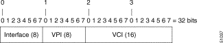
Identifies the RBE-enabled virtual circuit through which this DHCP request has come in. See Figure 4-6 for the format of this field. (4 bytes) |
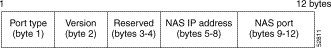
Figure 4-6 shows the format of the network access server (NAS) port field in the agent remote ID suboption.
Use the Cisco IOS ip dhcp relay information option global configuration command to activate the Option-82 feature.
Netflow is used for accounting. On the PE routers, Netflow is used to provide per flow usage accounting. The Netflow Collector provides Netflow usage data collection statistics such as time of first packets, time of last packet, number of packets, and number of octets used for performance reporting, capacity planning, and usage based billing. VPNSC collects the usage records from the Netflow Collector(s) and correlates them with the VPN service layer information.
A flow is identified by source address, source port, destination address, destination port, and more. When configured for Netflow accounting, the VHG/PE collects per flow accounting data and exports it to a Netflow Collector workstation, which stores it in flat files. A Netflow Analyzer is then used for analyzing the collected data.
Network management, fault monitoring, and SLA reporting are management functions performed in the core ATM network.
Network management components for RBE remote access consist of the following:
Fault monitoring is performed at the device, and service levels.
At the device level, fault monitoring is performed by the element managers (CEMF has an event manager component). CAM provides fault monitoring per dial port.
CIC is user at the service level to provide event correlation and filtering, monitoring, customer and administrative partitioning, and flow-through integration to other systems. CIC is an OEM product from Micromuse's NetCool. CIC's release 2.0 provides eventing at the IP VPN service level through integration with VPNSC.
SLA reporting is performed using the Service Assurance Agent (SA Agent) in IOS. At conventional MPLS VPN customer sites, VPNSC configures the SA Agent probes on managed CE routers, or shadow CE routers. At remote access sites, there is no real CE router so the SA Agent probes are configured on the PE routers at the PoPs. It is not possible to configure them on the NASs, because a NAS is not connected to a specific VPN so the probes are not routed using the VRFs. VPNSC collects statistics from the SA Agent MIB, and provides reports on a per VPN basis. For PPP users, performance numbers are derived from AR. The SA Agent probes are configured on the DSL routers at the CPE.
Performance and SLA reporting can be provided at a VPN service level through integration with VPNSC. RPMS is used to provide SLA information regarding incoming call rates per VPN customer.
Configuration of RBE to MPLS VPN integration is very similar to configuration of RFC 1483 remote access integration, except that the PVC is configured to RBE.
Perform the following steps to configure the VHG/PE.
|
Note Commands in a and b create a general loopback interface used for reachability to the router and are used as a source IP address for sessions (IBGP, TDP, etc.). |
c. Router (config-if)# interface loopback [number]
|
Note Commands c, d, and e create a loopback interface in a VRF necessary only if you use ip unnumbered interfaces to the CE device when you would ip unnumber the interface to this loopback. These steps are repeated for each customer VRF you ip unnumber interfaces to. |
Step 2 Define PVCs.
a. Router (config)# interface ATM0/0/0.[number] point-to-point (for the Cisco 6400). For example, interface ATM0/0/0.1 point-to-point
Router (config)# interface ATM[slot]/[port].[number] point-to-point (for the Cisco 7200). For example, interface ATM4/0.1 point-to-point
b. Router (config-if)# ip vrf forwarding [vpn name]
c. Router (config-if)# ip unnumbered Loopback [number]
|
Note If you are configuring an interface as unnumbered to a loopback interface, the loopback interface needs to be in the same VRF. |
d. Router (config-if)# pvc [vpi/vci number]
Step 3 Configure label switching on the interface connected to the MPLS cloud.
For connecting to a MPLS cloud using MPLS ATM tagging, perform the following commands:
|
Note Use the command above for the Cisco 6400. For the Cisco 7200, use interface ATM[slot]/[port].[number]. |
b. Router (config-if)# ip address [ip address]
For frame-based tagging, the equivalent commands would be:
|
Note Use the command above for the Cisco 6400. For the Cisco 7200, use interface ATM[slot]/[port].[number]. |
b. Router (config-if)# ip address [ip address]
c. Router (config-if)# tag-switching ip
|
Note For NSP configuration details refer to Configuring Multiprotocol Label Switching on the Cisco 6400
UAC at http://www.cisco.com/univercd/cc/td/doc/product/dsl_prod/6400/softnote/mpls_cfg.htm |
Step 4 Configure the VRF for each VPN.
a. Router (config)# ip vrf [vpn name]
b. Router (config-vrf)# rd [route descriptor]
c. Router (config-vrf)# route-target export [route target communities]
d. Router (config-vrf)# route-target import [route target communities]
Step 5 Configure a dedicated PVC for each VPN (PTA-MD).
|
Note Use the command above for the Cisco 6400. For the Cisco 7200, use interface ATM[slot]/0.[number]. |
b. Router (config-if)# ip vrf forwarding [vpn name]
c. Router (config-if)# ip address [ip address]
Step 6 Configure BGP to advertise the networks for each VPN.
a. Router (config)# router bgp [autonomous system number of sp]
b. Router (config-router)# neighbor [ip address of remote pe] remote-as [same autonomous number]
c. Router (config-router)# neighbor [ip address of remote pe] update-source Loopback0
d. Router (config-router)# address-family vpnv4
e. Router (config-router-af)# neighbor [ip address of remote pe] activate
f. Router (config-router-af)# neighbor [ip address of remote pe] send-community extended
Step 7 If using static routes, define them and redistribute them into BGP.
Step 8 Enable RBE on the interface:
|
Note Use the command above for the Cisco 6400. For the Cisco 7200, use interface ATM[slot]/0.[number]. |
Perform the following steps to configure DHCP Option 82 support for RBE.
Step 2 If you are on a non Cisco 6400 platform, specify the IP address of an interface on the DHCP relay agent that will be sent to the DHCP server via the Agent Remote ID suboption.
Step 3 Specify the ip helper address on the DSL interface:
Perform the following step to configure the DSLAMS using CDM.
For Cisco DSL Manager (CDM) configuration details, refer to
http://www.cisco.com/univercd/cc/td/doc/product/rtrmgmt/cdm/cdm33/index.htm
The modem is configured to forward DHCP requests unaltered to the VHG/PE for DHCP relay. If the VHG/PE interface is a numbered interface with the ip-helper command configured, the GIADDR field of the DHCP discover packet is set to the IP address of the VHG/PE interface. This allows the DHCP scope to be provisioned on the CNR server accordingly.
If the VHG/PE interface is unnumbered to a loopback interface, the GIADDR field of the DHCP discover packet is set to the IP address of the loopback interface. If several interfaces are unnumbered to the same loopback interface, the CNR server relies on the client MAC address to determine the correct IP address to supply. This entails configuring client class processing on the CNR server.
For Cisco Network Registrar (CNR) configuration details, refer to http://www.cisco.com/univercd/cc/td/doc/product/rtrmgmt/ciscoasu/nr/nr3-5/index.htm
For VPNSC configuration details, refer to the MPLS VPNSC documentation suite at http://www.cisco.com/univercd/cc/td/doc/product/rtrmgmt/index.htm .
For VPNSC configuration details, refer to the MPLS VPNSC documentation suite at http://www.cisco.com/univercd/cc/td/doc/product/rtrmgmt/index.htm .
Example 4-1 shows an example of an RBE configuration, with the interface unnumbered.
The topology of an integrated DSL remote access PPPoX with SSG to MPLS VPN solution is illustrated in Figure 4-7. PPPoX to SSG permits a remote user to select a desired service (ISP, enterprise VPN, etc.) provided through a separate MPLS VPN in the core. A remote user can switch between services dynamically and be logged on to multiple services simultaneously. The Service Selection Gateway (SSG), the Service Selection Dashboard (SSD), and the Radius server interact with each other to provide the service selection functionality.
Each service an SSG supports corresponds to an MPLS VPN. For each service supported on the SSG, a RFC 1483 PVC is configured between the SSG and the PE router. The PVC terminates at the PE router and is statically mapped to a VRF.
A DSL router is used to connect the remote access users to the SP DSL access network. In remote access PPPoX with SSG, the supported DSL routers are the Cisco 82x series, 14xx series, or SOHO77. At the residential side, the DSL router is attached to a LAN connecting to the remote users' host PCs.
The SP access network is a DSL access network with Cisco 6xx0 DSLAMs.
The Service Selection Gateway (SSG) is a software feature that runs on the 6400 NRP. The SSG permits remote users to use a single PPP session to log on to multiple services simultaneously. The set of services offered by a particular SSG must be known in advance. For each service an RFC 1483 PVC must be provisioned between the SSG NRP and the PE router to carry that service's traffic.
The Access Registrar (AR) is the Radius server used for this solution. The AR stores two types of records: user profiles and service profiles. The vendor-specific attributes used by the SSG must be supported by the AR.
The Access Registrar Release 1.5 is used and runs on a Sun Sparc workstation with Solaris 2.6 or 2.7, 128 MB of RAM, 80 MB disk space.
A single AR safely processes up to 800 calls per second (one request per call), without losses, in case of performing authentication and authorization only, and can process up to 300 calls per second (three requests per call) in case of performing authentication, authorization, accounting, and address management.
The following address management alternatives are available to a PPPoX user when it first logs on to the SSG:
If the address assigned when the user first logs on to the SSG is valid across all services this user selects afterwards, then there will be no need for assigning a new IP address for each service that user selects. This is a configurable option.
If the SSG service is not configured to reauthenticate the user, the user can be added to the service directly without proxying other servers. However, if the SSG service is configured to reauthenticate the user prior to joining the service, SSG queries that VPN's Radius server to authenticate the user.
When the remote user first logs on to the SSG, the SSG authenticates the user with the SP Radius server. The response from SP Radius includes a list of services this user is authorized to access. The SSG creates a host object and stores the list of authorized services.
When the remote user attempts to log on to a service it is authorized to use, the SSG queries the SP Radius server for more detailed authorization information for the service. The SP Radius server responds with that service's service profile, which includes among others: the service type, the address of the remote Radius server (VPN Radius server), and the address of the remote DNS server (VPN Radius server).
The SSG can be configured for PPP users and connections to perform the following accounting actions:
On the PE routers, Netflow is used to provide per flow usage accounting (since Netflow needs to be enabled on the PE, the PE needs to support Netflow to support accounting). The Netflow Collector provides Netflow usage data collection used for performance reporting, capacity planning, and usage based billing. VPNSC collects the usage records from the Netflow Collector(s) and compares them with VPN service layer information.
The Service Selection Dashboard (SSD) is a specialized web server that allows a user to its web browser for service selection. Once the user selects a service, the SSD forwards relevant information: user name, user password (if required), and service name to the SSG for authentication and service connectivity.
Each SSG must have its own SSD, i.e., 1:1 mapping.
The following SSD software release is to be used: Altair-Dashboard, Version Number: 2.2s(1.12) Build 012.
The RFC 1483 PVCs connecting the SSGs to a PE router must be provisioned. Each PVC is statically mapped to a VRF on that PE router. Each PE router supports up to 400 VRFs.
The PE router terminates up to 2000 PVCs. On the MPLS VPN side, a PE can maintain 400 VRFs. This is within all three platform limits, since the maximum number of PVC sessions. The maximum number of VRFs is limited by the maximum number of interfaces.
More than one PE router in the same PoP can be configured with the same VRF.
The exact IOS release depends on the release schedule for the "overlapping local pools" feature.
DSL PPPoX to SSG supports two types of core networks, IP MPLS, and ATM MPLS.
The network management components relevant for this solution are:
Fault monitoring is performed at the device, and service levels.
At the device level, fault monitoring is performed by the element managers (CEMF has an event manager component). CAM provides fault monitoring per dial port.
CIC is user at the service level to provide event correlation and filtering, monitoring, customer and administrative partitioning, and flow-through integration to other systems. CIC is an OEM product from Micromuse's NetCool. CIC's release 2.0 provides eventing at the IP VPN service level through integration with VPNSC.
SLA reporting is performed using the Service Assurance Agent (SA Agent) in IOS. In conventional MPLS VPN customer sites, VPNSC configures SA Agent probes on managed CE routers or shadow CE routers. However, in remote access sites, there are no real CE router. The SA Agent probes is configured on the PE routers at the PoPs. It is not possible to configure them on the NASs, because a NAS is not connected to any particular VPN so the probes are not routed using the VRFs. VPNSC collects statistics from the SA Agent MIB and provides reports on a per VPN basis. For PPP users, performance numbers is derived from AR.
Concord's Net Health provides performance and SLA reporting at a VPN service level through integration with VPNSC.
RPMS is used to provide SLA information on such measures as incoming call rates for each VPN customers.
The SA Agent probes are configured on the DSL routers at the CPE for reporting on PPPoA connections, but not for the PPPoE connections which are initiated by the host PCs behind the DSL routers. Configure multiple SA probes on the DSL router, one for each of VPN service accessed through that router.
Perform the following two log on event sequences before provisioning the DSL PPPoX Integration.
Perform the following steps to log on to the SSG:
Step 2 The SSG receives the remote user's user id and password and queries the SP Radius server to authenticate the remote user.
Step 3 The SP Radius server responds to the SSG with the remote user's User Profile (the user profile includes the list of services this user is allowed to access).
Step 4 The SSG accepts the PPP session.
Step 5 An IP address is allocated to the remote user either by the SP Radius server, or from a local pool on the SSG. This address could be either a private or a public IP address.
Step 6 The assigned address is propagated back to the user using IPCP.
Step 7 The SSG creates a host object for the remote user, and the user gets access to the default service only. The default service includes access to the SSD.
Perform the following steps to log on to a service:
Step 2 The SSD initiates a request to the SSG with user name, password, and service name.
Step 3 The SSG queries the SP Radius server and receives the service profile in response. The service profile includes, among others, the service type and the address of the service's (=VPN's) Radius server. The SSG creates a service object for that service.
Step 4 If the service type is "passthrough", no authentication is required. If the service type is "proxy", the SSG queries the VPN's Radius server to authenticate the remote user. The query is routed over the appropriate RFC 1483 PVC to the PE router then forwarded to that VPN's VRF. Note: A route back to the SSG must be redistributed into the VRF in order for the reply from the VPN's Radius server to be successfully routed back to the SSG (part of provisioning).
Step 5 The SSG assigns an address to the remote user. The address may come from:
Step 6 The SSG creates a connection object linking the remote user's host object to the service object. The SSG currently can not propagate a route to the remote host to the PE router in order to inject injects it into the VRF. Routes corresponding to the entire address pool corresponding to a service must currently be provisioned into that service's VRF.
Step 7 The SSG can not propagate the address assigned to the remote user back to the user, because the remote user may access multiple services (VPNs) simultaneously over the same PPPoX session. The user will always use the address it received in Step 5 as its source address. The SSG will differentiate between packets from the same user to different VPNs based on the destination address. This implies that a single remote host can not be logged on the two VPNs using overlapping address spaces simultaneously. The SSG must apply NAT to the source address of packets from the remote host to the VPN and it must apply NAT to the destination address of packets from the VPN to the remote host. An exception to this is when the user IP address assigned in Step 5 is valid and unique across all services the user is logged on to. In this case NAT need not be applied, and the user does not even have to be allocated a different IP address for each service. The IP address of Step 5 is sufficient in this case.
Provisioning Cisco DSL PPPoX with SSG to MPLS VPN entails:
1. Initial Configuration through pre-staging of the routers, using config Xpress, using an element manager (for example, SCM), using CIPM templates, or any combination of the above. This configuration is not tied to VPN services per se. It includes:
2. Although this is tied to customer provisioning, it is different from the VPN service provisioning (for example,, add a site to VPN). An example would be a customer with an existing VPN requests access for dial-up users. It includes:
a. configuration of the different network servers: AR, CNR
b. configuring the SSG NRP for a service: adding the RFC 1483 PVCs connecting to the PE router. This can be done using the SCM.
c. configuring the PE router for a service: adding the required VRF configuration and the RFC 1483 PVCs connecting to the SSG. This is performed using VPNSC 2.
3. VPN service configurations are critically repetitive tasks to automate that include:
a. actual service activation, performed by VPNSC, where a VPN is created, and CE sites and remote access sites are added to it.
|
Note For VPNSC configuration, refer to the MPLS VPNSC documentation suite at http://www.cisco.com/univercd/cc/td/doc/product/rtrmgmt/index.htm. |
Perform the following steps to configure the PE routers.
|
Note Command in a and b create a general loopback interface used for reachability to the router and are also used as a source IP address for sessions (IBGP, TDP, etc.). |
c. Router (config-if)# interface loopback [number]
|
Note Commands c, d, and e create a loopback interface in a VRF necessary only if you use ip unnumbered interfaces to the CE device when you would ip unnumber the interface to this loopback. These steps are repeated for each customer VRF you ip unnumber interfaces to. |
Step 2 Configure the VRF for each VPN.
a. Router (config)# ip vrf [vpn name]
b. Router (config-vrf)# rd [route descriptor]
c. Router (config-vrf)# route-target export [route target communities]
d. Router (config-vrf)# route-target import [route target communities]
Step 3 Configure label switching on the interface connected to the MPLS cloud.
For connecting to a MPLS cloud using MPLS ATM tagging, perform the following commands:
a. Router (config-if)# interface ATM0/0/0.[number] tag-switching
b. Router (config-if)# ip address [ip address]
For frame-based tagging, the equivalent commands would be:
a. Router (config-if)# interface ATM0/0/0 [number]
b. Router (config-if)# ip address [ip address]
c. Router (config-if)# tag-switching ip
|
Note For NSP configuration details refer to Configuring Multiprotocol Label Switching on the Cisco 6400
UAC at http://www.cisco.com/univercd/cc/td/doc/product/dsl_prod/6400/softnote/mpls_cfg.htm |
Step 4 Configure a dedicated PVC for each VPN (PTA-MD).
a. Router (config)# interface ATM0/0/0.[number] point-to-point
b. Router (config-if)# ip vrf forwarding [vpn name]
c. Router (config-if)# ip address [ip address]
Step 5 Configure BGP to advertise the networks for each VPN.
a. Router (config)# router bgp [autonomous system number of sp]
b. Router (config-router)# neighbor [ip address of remote pe] remote-as [same autonomous number]
c. Router (config-router)# neighbor [ip address of remote pe] update-source Loopback0
d. Router (config-router)# address-family vpnv4
e. Router (config-router-af)# neighbor [ip address of remote pe] activate
f. Router (config-router-af)# neighbor [ip address of remote pe] send-community extended
Step 6 If using static routes, define them and redistribute them into BGP.
For configuration details of the Cisco 6400, refer to the 6400 documentation suite at http://www.cisco.com/univercd/cc/td/doc/product/dsl_prod/6400/index.htm
Perform the following steps to configure the SSG NRP.
Step 2 If using PPPoE, define a VPDN group that accepts PPPoE and specifies a virtual template to use.
a. Router (config)# vpdn enable
b. Router (config)# vpdn-group <group number>
c. Router (config-vpdn)# accept-dialin
d. Router (config-vpdn-acc-in)# protocol pppoe
e. Router (config-vpdn-acc-in)# virtual-template <virtual template number>
Step 3 Configure the Subscriber PPP/ATM termination. (See section 6.4 of the URL)
a. Router (config)# interface ATM0/0/0.[number] point-to-point
b. Router (config-if)# ip unnumbered Loopback0
|
Note For PPPoA, the encapsulation command is Router (config-i-pvc)# encapsulation aal5mux ppp Virtual-Template1 |
Step 4 Configure the AAA server information. (See section 6.5 of the URL)
Step 5 Configure the SSG information.
a. Router (config)# ssg enable
b. Router (config)# ssg default-network [ssd ip address]
c. Router (config)# ssg service-password [password]
d. Router (config)# ssg radius-helper auth-port 1645 acct-port 1646
e. Router (config)# ssg radius-helper key [password]
f. Router (config)# ssg bind service [vpn name] [next-hop-interface]
Step 6 Configure the PTA-MD. (See section 6.3 of the URL)
Step 7 Configure Routing information. (See section 6.8 of the URL)
Perform the following steps to configure the customer DSL routers.
Step 2 Configure the PPP information.
For PPPoA, configure the router to bridge as follows.
For DSL router configuration details, refer to http://www.cisco.com/univercd/cc/td/doc/product/dsl_prod/c600s/index.htm
Perform the following steps to configure the AR network server.
--> set ipaddress [ip address]
--> set sharedsecret [sharedsecret]
Step 2 Define the users in the Userlists database.
--> add /Radius/Userlists/[userlist name]
--> cd /Radius/Userlists/[userlist name]
--> set baseprofile [profile name]
Step 3 Define a profile for each user in the database.
--> cd [profile name]/attributes
--> set framed-ip-addres [ip address]
--> set account-info "[vpn1] [vpn2] [vpnn]"
Step 4 Define services (vpn) in the Userlists database.
--> add /Radius/Userlists/[service name]
--> cd /Radius/Userlists/[service name]
--> set baseprofile [profile name]
Step 5 Define a profile for each service.
--> cd [profile name]/attributes
--> set service-info "[Iservice-name Tservice-type Mservice-mode Rservice-routing ...]"
For Access Registrar (AR) configuration details, refer to http://www.cisco.com/univercd/cc/td/doc/product/rtrmgmt/cnsar/index.htm
The 67X modem is configured to forward DHCP requests unaltered to the 6400. If the 6400 interface is a numbered interface with the ip-helper command configured, the GIADDR field of the DHCP discover packet is set to the IP address of the 6400 interface. This allows the DHCP scope to be provisioned on the CNR server accordingly.
If the 6400 interface is unnumbered to a loopback interface, the GIADDR field of the DHCP discover packet is set to the IP address of the loopback interface. If several interfaces are unnumbered to the same loopback interface, the CNR server relies on the client MAC address to determine the correct IP address to supply. This entails configuring client class processing on the CNR server.
For Cisco Network Registrar (CNR) configuration details, refer to http://www.cisco.com/univercd/cc/td/doc/product/rtrmgmt/ciscoasu/nr/nr3-5/index.htm
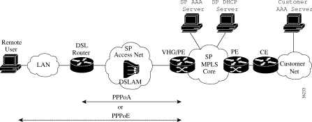
The topology of an integrated DSL remote access PPPoX to MPLS VPN solution is illustrated in Figure 4-8 using a VPN capable service provider's MPLS backbone. In PPPoX remote access, the VHG/PE terminates an incoming PPPoX session and maps the remote user to the corresponding VRF.
A DSL router is used to connect the remote access users to the SP DSL access network. In PPPoX remote access, the supported DSL routers are the Cisco 82x series, 14xx series, or SOHO77. At the residential side, the DSL router is attached to a LAN connecting to the remote users' host PCs.
The SP access network is a DSL access network with Cisco 6xx0 DSLAMs.
The following VHG/PE platforms are used in Cisco PPPoX remote access to MPLS.
Each VHG/PE accepts up to 300 L2TP tunnels carrying a total of 2000 PPP sessions. On the MPLS VPN side, a PE can maintain 400 VRFs. This is within all three platform limits, since the maximum number of PPP sessions. The maximum number of VRFs is limited by the maximum number of interfaces.
Since each 7x00/NRP router can terminate only 2048/3000 PPP sessions, about 33/50 7x00/NRP routers are configured as VHG/PEs per PoP. More than one PE router in the same PoP can be configured with the same VRF.
Each VHG/PE router must be configured with appropriate VRFs. Each VRF must be enabled on the VHG/PE router by creating a loopback interface and configuring it to forward all packets to the VRF. 400 IDBs is consumed to enable 400 VRFs on VHG/PE.
The Access Registrar (AR) is the Radius server used in this solution. There may need to be multiple Radius servers in the network, depending on:
In large solutions, where a single PoP has 100,000 ports, it may be economical to allocate a Local SP Radius server for the NASs in each PoP. The VHG/PEs sends the requests to Radius servers to a separate set of SP Radius servers, the one residing in the core.
The NASs and VHG/PEs only query the SP's Radius servers. An SP Radius server must be capable of proxying authentication and accounting requests to the relevant VPN Radius servers. The AR has this capability. However, the VPN Radius server can be using private addresses and may be unreachable through the global routing table. For the SP Radius server to communicate with the VPN Radius servers it must be made part of a management VPN.
See "AAA Radius Access to MPLS VPN Integration" for details on using Radius for AAA and address management.
The solution supports the following alternatives:
A single AR can safely process up to 800 calls per second (one request per call), without losses, in case of performing authentication and authorization only, and it can process up to 300calls per second (three requests per call) in case of performing authentication, authorization, accounting, and address management.
A PE assigns addresses to remote users through:
The following functions are provided:
Upon receipt of an incoming PPP session, the VHG/PE sends an Access-Request to the SP Radius server. The SP Radius server authorizes the PPP session based on the remote user's domain name or DNIS, and associates the PPP session with a specific VPN. The VPN is returned to the interface as configuration commands to be applied to the virtual interface being created for that PPP session.
Based on the domain name or DNIS, the SP Radius server proxies the request to the appropriate VPN Radius server for authenticating the remote user. Alternately, the SP Radius server can complete the authentication itself. See "AAA Radius Access to MPLS VPN Integration" for details.
Accounting is provided by the AAA records in AR for the PPP users and is required if the SP Radius server is used for address management.
The VHG/PE is configured to send accounting records to the SP Radius server. The accounting mode is start-stop or stop-only. SP Radius server, and Proxy accounting functions are provided.
The SSG can be configured for PPP users and connections to perform the following accounting actions:
On the PE routers, Netflow is used to provide per flow usage accounting (since Netflow needs to be enabled on the PE, the 6400 needs to support Netflow for this feature to be supported, which is not the case yet). The Netflow Collector provides collection of Netflow usage data that can be used for performance reporting, capacity planning and usage based billing. VPNSC collects the usage records from the Netflow Collector(s) and correlates them with the VPN service layer information.
DSL Single-Card PPPoX supports two core network types, IP MPLS and ATM MPLS.
The VPN Solutions Center (VPNSC) is the primary tool used to provision a management VPN for all managed sites. The management VPN is required for applications that need access to a customer's VPN.
In Single-Card PPPoX MPLS VPN those applications are VPNSC, CIPM, and SP Access Registrar (where it proxies to a customer AAA server).
The configuration of the management VPN for the VPNSC and CIPM applications is generic to all managed MPLS VPN solutions described in other documents. For example. the way the management VPN is configured by VPNSC, it only allows applications on the management VPN to access the managed PE and CE routers.
In case of Radius proxy, the following configuration is required:
The network management components relevant for this solution are:
Fault monitoring is performed at the device, and service levels.
At the device level, fault monitoring is performed by the element managers (CEMF has an event manager component). CAM provides fault monitoring per dial port.
CIC is user at the service level to provide event correlation and filtering, monitoring, customer and administrative partitioning, and flow-through integration to other systems. CIC is an OEM product from Micromuse's NetCool. CIC's release 2.0 provides eventing at the IP VPN service level through integration with VPNSC.
SLA reporting is performed using the Service Assurance Agent (SA Agent) in IOS. In conventional MPLS VPN customer sites, VPNSC configures SA Agent probes on managed CE routers or shadow CE routers. However, in remote access sites, there are no real CE router. The SA Agent probes is configured on the PE routers at the PoPs. It is not possible to configure them on the NASs, because a NAS is not connected to any particular VPN so the probes are not routed using the VRFs. VPNSC collects statistics from the SA Agent MIB and provides reports on a per VPN basis. For PPP users, performance numbers is derived from AR.
Concord's Net Health provides performance and SLA reporting at a VPN service level through integration with VPNSC.
RPMS is used to provide SLA information on such measures as incoming call rates for each VPN customer.
The SA Agent probes are configured on the DSL routers at the CPE for reporting on PPPoA connections, but not for the PPPoE connections which are initiated by the host PCs behind the DSL routers. Configure multiple SA probes on the DSL router, one for each of VPN service accessed through that router.
Perform the following steps for creating a PPPoX session over DSL to access its corporate network or ISP as a remote user, the customer network in Figure 4-8.
Step 2 The VHG/PE accepts and terminates the PPPoX session.
Step 3 The VHG/PE queries Radius to associate the remote user with a specific customer MPLS VPN. The VPN's VRF (routing table and other information associated with a specific VPN) must have been pre-instantiated on the VHG/PE. See
Step 4 The VHG/PE completes the remote user's authentication through Radius.
Step 5 The VHG/PE obtains an IP address for the remote user.
Step 6 The remote user is now part of the customer VPN. Packets can flow from/to the remote user.
Provisioning Cisco VPN DSL PPPoX remote access to MPLS entails:
1. Initial configuration through router pre-staging, using config Xpress, using an element manager (for example, SCM), using CIPM templates, or any combination of the above. This configuration is not necessarily tied to VPN services and includes:
2. Although this is tied to customer provisioning, it is different from the VPN service provisioning (for example,, add a site to VPN). An example would be a customer with an existing VPN requests access for dial-up users. It includes:
a. configuration of the different network servers: AR, CNR
b. configuring the VHG/PE for a new customer by adding the required VRF configuration, address pools, and virtual templates through VPNSC 2 using templates from IP Manager (CIPM).
3. VPN service configurations are critically repetitive tasks to automate that include:
a. actual service activation, performed by VPNSC, where a VPN is created, and CE sites and remote access sites are added to it.
|
Note For VPNSC configuration, refer to the MPLS VPNSC documentation suite at http://www.cisco.com/univercd/cc/td/doc/product/rtrmgmt/index.htm. |
Perform the following steps to configure the VHG/PE router.
|
Note Commands in a and b create a general loopback interface used for reachability to the router and are used as a source IP address for sessions (IBGP, TDP, etc.). |
c. Router (config-if)# interface loopback [number]
|
Note Commands c, d, and e create a loopback interface in a VRF necessary only if you use ip unnumbered interfaces to the CE device when you would ip unnumber the interface to this loopback. These steps are repeated for each customer VRF you ip unnumber interfaces to. |
Step 2 Configure the VRF for each VPN.
a. Router (config)# ip vrf [vpn name]
b. Router (config-vrf)# rd [route descriptor]
c. Router (config-vrf)# route-target export [route target communities]
d. Router (config-vrf)# route-target import [route target communities]
Step 3 Configure the virtual template.
a. Router (config)# interface virtual-template[number]
Step 4 Configure BGP to advertise the networks for each VPN.
a. Router (config)# router bgp [autonomous system number of sp]
b. Router (config-router)# neighbor [ip address of remote pe] remote-as [same autonomous number]
c. Router (config-router)# neighbor [ip address of remote pe] update-source Loopback0
d. Router (config-router)# address-family vpnv4
e. Router (config-router-af)# neighbor [ip address of remote pe] activate
f. Router (config-router-af)# neighbor [ip address of remote pe] send-community extended
Step 5 If using static routes, define them and redistribute them into BGP.
Refer to Table 4-2 for Cisco PE router product URLs:
| Component | URL |
|---|---|
http://www.cisco.com/univercd/cc/td/doc/product/core/index.htm |
|
http://www.cisco.com/univercd/cc/td/doc/product/dsl_prod/6400/index.htm |
Perform the following steps to configure the AR and CNR network servers on the VHG/PE.
|
Note Configuring CNRnetwork servers is optional since it only needs to be performed for assigning IP addresses to users with a DHCP server, or to do DHCP relays. |
Step 2 If using PPPoE, define a VPDN group that accepts PPPoE and specifies a virtual template to use.
a. Router (config)# vpdn enable
b. Router (config)# vpdn-group <group number>
c. Router (config-vpdn)# accept-dialin
d. Router (config-vpdn-acc-in)# protocol pppoe
e. Router (config-vpdn-acc-in)# virtual-template <virtual template number>
Step 3 Define authentication and accounting on the VHG/PE to point to the appropriate AR server(s).
Step 4 Enable the VHG/PE to use the Radius protocol for authorization and authentication.
a. Router (config)# aaa new-model
b. Router (config)# aaa authentication ppp default local group radius
c. Router (config)# aaa authorization network default local group radius
Step 5 Define necessary share secrets to properly communicate with the Radius server on the VHG/PE.
|
Note The sharedsecret has to be the same as the sharedsecret defined in Step 1d of "Configuring the AR Network Server". |
Step 6 Define local pools if using local pool addressing.
Perform the following steps to configure the AR network server.
Step 2 Define VPN users for each customer group.
Step 3 Define profile containing the necessary attributes.
One required attribute for single card PPPoA or PPPoE is to pass a Cisco attribute value pair (AV-Pair) to configure the interface into a VRF. Exemplified as follows:
|
Note This assumes the user is attached to vpn200, that I used lo200 as my interface address, and that I have an address pool defined on the PE router called 1cardpppoa_pool_vpn200. |
For Access Registrar (AR) configuration details, refer to http://www.cisco.com/univercd/cc/td/doc/product/rtrmgmt/cnsar/index.htm
The 67X modem is configured to forward DHCP requests unaltered to the 6400. If the 6400 interface is a numbered interface with the ip-helper command configured, the GIADDR field of the DHCP discover packet is set to the IP address of the 6400 interface. This allows the DHCP scope to be provisioned on the CNR server accordingly.
If the 6400 interface is unnumbered to a loopback interface, the GIADDR field of the DHCP discover packet is set to the IP address of the loopback interface. If several interfaces are unnumbered to the same loopback interface, the CNR server relies on the client MAC address to determine the correct IP address to supply. This entails configuring client class processing on the CNR server.
For Cisco Network Registrar (CNR) configuration details, refer to http://www.cisco.com/univercd/cc/td/doc/product/rtrmgmt/ciscoasu/nr/nr3-5/index.htm
Perform the following steps to configure the VHG/PE for a new customer. Refer to "Configuring the VHG/PE Routers".
Step 2 Attach a generic virtual template to the PVC.
A final configuration would look like the following:
|
Note This assumes you have a virtual template configured that will be combined with user specific information passed from the AAA server. |
Perform the following steps to configure a customer DSL routers.
Step 2 If using PPPoA, configure necessary PPP information on the DSL router such as username and password. Other information is optional depending on user requirements.
Step 3 If using PPPoE, configure the DSL router to bridge the ethernet frames into the WAN ATM interface.
For DSL router configuration details, refer to http://www.cisco.com/univercd/cc/td/doc/product/dsl_prod/c600s/index.htm
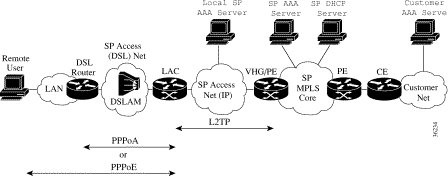
Figure 4-9, depicts the topology of an integrated DSL L2TP to MPLS VPN access solution. It shows a topology with a VPN capable service provider's MPLS backbone. In Figure 4-9, the customer is outsourcing all remote access operations to its service provider. The service provider operates an MPLS VPN that interconnects all customer sites. Incoming PPPoX sessions, arriving at the LAC, are L2TP-tunneled to the VHG/PE that maps it to the corresponding VRF. This solution provide enhanced aggregation and route summarization at the edge of the MPLS VPN core. This solution is similar to the dial in L2TP to MPLS VPN solution discussed in Chapter 2.
A DSL router is used to connect the remote access users to the SP DSL access network. In DSL L2TP remote access, the supported DSL routers are the Cisco 82x series, 14xx series, or SOHO77. At the residential side, the DSL router is attached to a LAN connecting to the remote users' host PCs. Specify PPPoE software for the PCs.
The SP access network consists of two components:
The access network could be a high-speed LAN or an ATM network. Like the NASs and VHG/PEs, a Radius server may need to be placed in each Access Network (PoP).
The following VHG/PE platforms are used in Cisco DSL L2TP remote access to MPLS.
Each VHG/PE is capable of accepting up to 300 L2TP tunnels carrying a total of 2000 PPP sessions. On the MPLS VPN side, a PE is capable of maintaining 400 VRFs. These numbers are within the limits of all three platforms, since the maximum number of PPP sessions, and also the maximum number of VRFs, is limited by the maximum number of interfaces.
Since each 6400/7x00/NRP router can terminate only 2048/3000 PPP session, about 50/33 7x00/NRP routers are configured as VHG/PEs per PoP. More than one PE router in the same PoP can be configured with the same VRF.
Each VHG/PE router must be configured with appropriate VRFs. Each VRF must be pre-instantiated on the VHG/PE router. This is performed by creating a loopback interface and configuring it to forward all packets to the VRF. 400 IDBs is consumed to pre-instantiate 400 VRFs on VHG/PE.
The LAC platform is the 6400 NRP. It receives incoming PPPoX sessions and L2TP-tunnels them to the VHG/PE.
When configured as a LAC the 6400 NRP processes up to 2000 PPPoX sessions and 50 L2TP tunnels (one tunnel to each VHG/PE in the same access network).
The Access Registrar (AR) is the Radius server used for this solution. There may need to be multiple Radius servers in the network, depending on:
In large solutions, where a single PoP has 100,000 ports, it may be economical to allocate a Local SP Radius server for the NASs in each PoP. The VHG/PEs sends the requests to Radius servers to a separate set of SP Radius servers, the one residing in the core.
The NASs and VHG/PEs only query the SP's Radius servers. A SP Radius server must be capable of proxying authentication and accounting requests to the relevant VPN Radius servers. The AR has this capability. However, the VPN Radius server can be using private addresses and may be unreachable through the global routing table. For the SP Radius server to communicate with the VPN Radius servers it must be made part of a management VPN.
The AR when queried by the NASs provides for tunnel authorization only, and when queried by the VHGs provide AAA and optionally address management functions. In case of small-scale solutions, the same AR may be used by both the NAS and the VHG/PE. The AR must be configured to differentiate between the a request from a NAS and a request from a VHG/PE. A NAS's request has service-type=Outbound-User while a VHG/PE's request has a service-type=Framed-User. In larger solutions the NASs can be configured with different AAA servers than those configured on the VHG/PEs.
See "AAA Radius Access to MPLS VPN Integration" for details on using Radius for AAA and address management.
The solution supports the following alternatives:
A single AR can safely process up to 800 calls per second (one request per call), without losses, in case of performing authentication and authorization only, and it can process up to 300calls per second (three requests per call) in case of performing authentication, authorization, accounting, and address management.
A PE assigns addresses to remote users through:
The DHCP server is Cisco Network Registrar (CNR).
Accounting is provided by the AAA records in AR for the PPP users and is required if the SP Radius server is used for address management.
The VHG/PE is configured to send accounting records to the SP Radius server. The accounting mode is start-stop or stop-only. SP Radius server, and Proxy accounting functions are provided
On the PE routers, Netflow provides per flow usage accounting. The Netflow Collector provides of Netflow usage data collection used for performance reporting, capacity planning, and usage based billing. VPNSC collects the usage records from the Netflow Collector(s) and correlates them with VPN service layer information.
The DSL L2TP to MPLS VPN Integration solution supports two types of core networks, IP MPLS and ATM MPLS.
The VPN Solutions Center (VPNSC) is the primary tool used to provision a management VPN for all managed sites. The management VPN is required for applications that need access to a customer's VPN.
In dial L2TP MPLS VPN those applications are VPNSC, CIPM, and SP Access Registrar (where it proxies to a customer AAA server).
The configuration of the management VPN for the VPNSC and CIPM applications is generic to all managed MPLS VPN solutions described in other documents. For example. the way the management VPN is configured by VPNSC, it only allows applications on the management VPN to access the managed PE and CE routers.
In case of Radius proxy, the following configuration is required:
Network management considerations for DSL L2TP opposed to Dial L2TP are:
Network management components for DSL L2TP are:
The LAC retrieves the L2TP tunnel (VPDN) information from a Radius server, or local configuration.
Both methods allow load balancing among multiple VHG/PEs, but using Radius is more scalable. For load balancing, the Radius server returns a list of VHG addresses, and the LAC filters through that list in a specific order providing failover.
Both the AR and IOS support IETF standard tunnel attributes for passing tunnel information from the Radius to the NAS. These standard attributes are used instead of vendor-specific cisco-avpairs.
The VHG/PE is configured with a default VPDN to accept L2TP tunnels from any LAC or remote entity, or with VPDNs to only accept calls from LACs with given names (tunnels ids).
Other L2TP tunnels issues include:
In some scenarios, the number of remote users, belonging to the same VPN customer, expected to log on to certain PoP is so small, such that enabling a VRF on one of the VHG/PE routers at that PoP won't be economical. In such a case when the remote user dials into a LAC at that PoP, its PPP session is L2TP tunneled over the MPLS core to a VHG/PE router having the remote user's VRF pre-instantiated on it. This VHG/PE router can be located at a nearby PoP or, alternatively, multiple VHGs can be clustered together at a central location, a VHG farm. Each VHG still functions as a PE routers as well.
The L2TP tunnel from LAC to VHG is routed using the global routing table, and a single L2TP tunnel can carry PPP sessions of different VPN customers.
The following functions are provided:
Upon receipt of an incoming PPP session, the VHG/PE sends an Access-Request to the SP Radius server. The SP Radius server authorizes the PPP session based on the remote user's domain name or DNIS, and associates the PPP session with a specific VPN. The VPN is returned to the interface as configuration commands to be applied to the virtual interface being created for that PPP session.
Based on the domain name or DNIS, the SP Radius server proxies the request to the appropriate VPN Radius server for authenticating the remote user. Alternately, the SP Radius server can complete the authentication itself. See "AAA Radius Access to MPLS VPN Integration".
Fault monitoring is performed at the device, and service levels.
At the device level, fault monitoring is performed by the element managers (CEMF has an event manager component). CAM provides fault monitoring per dial port.
CIC is user at the service level to provide event correlation and filtering, monitoring, customer and administrative partitioning, and flow-through integration to other systems. CIC is an OEM product from Micromuse's NetCool. CIC's release 2.0 provides eventing at the IP VPN service level through integration with VPNSC.
SLA reporting is performed using the Service Assurance Agent (SA Agent) in IOS. In conventional MPLS VPN customer sites, VPNSC configures SA Agent probes on managed CE routers or shadow CE routers. However, in remote access sites, there are no real CE router. The SA Agent probes is configured on the PE routers at the PoPs. It is not possible to configure them on the LACs, because a LAC is not connected to any particular VPN so the probes are not routed using the VRFs. VPNSC collects statistics from the SA Agent MIB and provides reports on a per VPN basis. For PPP users, performance numbers is derived from AR.
Concord's Net Health provides performance and SLA reporting at a VPN service level through integration with VPNSC.
RPMS is used to provide SLA information on measures such as incoming call rates for each VPN customer.
The following events occur when the remote user creates a PPPoX session over DSL to access its corporate network or ISP (i.e. customer network of Figure 4-9):
Step 2 The LAC accepts the PPPoX session.
Step 3 The LAC partially authenticates the remote user with CHAP or PAP. The domain name is used to determine whether the user is a VPN client. The LAC queries a AAA server to determine if the user is a VPN client. If the user is not a VPN client (it is using the DSL service provider also as his ISP), authentication continues on the LAC. If the user is a VPN client, the AAA server will return the address of a VHG/PE and other L2TP tunnel information to the LAC.
Step 4 If an L2TP tunnel does not already exist, the LAC initiates a tunnel to the VHG/PE (LNS). The NAS and the VHG/PE authenticate each other before any sessions are attempted within a tunnel. It is also possible for a VHG/PE to accept tunnel creation without any tunnel authentication of the NAS.
Step 5 Once the tunnel exists, a session within the tunnel is created for the remote user and the PPP session is extended to terminate on the VHG/PE.
Step 6 The LAC propagates all available PPP information (the LCP negotiated options and the partially authenticated CHAP/PAP information) to the VHG/PE.
Step 7 The VHG/PE associates the remote user with a specific customer MPLS VPN. The VPN's VRF (routing table and other information associated with a specific VPN) has been already instantiated on the VHG/PE.
Step 8 The VHG/PE completes the remote user's authentication.
Step 9 The VHG/PE obtains an IP address for the remote user.
Step 10 The remote user is now part of the customer VPN. Packets can flow from/to the remote user.
Provisioning Dial L2TP access to MPLS VPN entails:
1. Initial configuration through router pre-staging, using config Xpress, using an element manager (for example, SCM), using CIPM templates, or any combination of the above. This configuration is not necessarily tied to VPN services and includes:
|
Note In this solution the Cisco IOS Command Line Interface (CLI) is used for configuring routers and Access Registrar (see "Cisco IOS Software Fundamentals"), and a Graphical User Interface (GUI) for CNR. |
2. Although this is tied to customer provisioning, it is different from the VPN service provisioning (for example, add a site to VPN). An example would be a customer with an existing VPN requests access for dsl users. It includes:
a. configuring access servers for new customers in one of the following methods
b. configuring the VHG/PE for a new customer
c. configuring components where user authentication & authorization takes place
d. configuring accounting on AR
e. configuring components where address management takes place
|
Note Customer and service configurations differ from VPN service configurations of adding a VPN site for a customer with an existing VPN who might request access for dsl users. |
3. VPN service configurations are critically repetitive tasks to automate, that include:
a. actual service activation, performed by VPNSC, where a VPN is created, and CE sites and remote access sites are added to it.
|
Note For VPNSC configuration, refer to the MPLS VPNSC documentation suite at http://www.cisco.com/univercd/cc/td/doc/product/rtrmgmt/index.htm. |
For miscellaneous component configuration details, refer to the following corresponding URLs:
Table 4-3 DSL L2TP miscellaneous component configurations
| Component | URL |
|---|---|
http://www/univercd/cc/td/doc/product/rtrmgmt/cnsar/index.htm |
|
Perform the following steps to configure the PE routers.
Step 2 Configure the IGP on the PE (OSPF, ISIS).
Step 3 Configure label switching on the interface connected to the MPLS cloud.
Step 4 Configure BGP peer from VHG to loopback on the remote PEs.
a. Router (config)# router bgp [autonomous system number of sp]
b. Router (config-router)# neighbor [ip address of remote pe] remote-as [same autonomous number]
c. Router (config-router)# neighbor [ip address of remote pe] update-source Loopback0
Step 5 Configure BGP session to exchange VPN-IPV4 prefixes.
a. Router (config-router)# address-family vpnv4
b. Router (config-router-af)# neighbor [ip address of remote pe] activate
c. Router (config-router-af)# neighbor [ip address of remote pe] send-community extended
Step 6 Define a VPDN group that accepts L2TP and specifies a virtual template to use.
a. Router (config)# vpdn enable
b. Router (config)# vpdn-group <group number>
c. Router (config-vpdn)# accept-dialin
d. Router (config-vpdn-acc-in)# protocol l2tp
e. Router (config-vpdn-acc-in)# virtual-template <virtual template number>
Step 7 Configure virtual profile and virtual interface.
Perform the following steps to configure the AR application with a new NAS or VHG when using the Radius protocol on the NAS or VHG.
--> set ipaddress [ip address]
--> set sharedsecret [sharedsecret]
For Access Registrar (AR) configuration details, refer to http://www.cisco.com/univercd/cc/td/doc/product/rtrmgmt/cnsar/index.htm
Perform the following steps to configure the LAC or VHG/PE, or both, with an AAA server.
a. Router (config)# Router (config)# aaa new-model
b. Router (config)# aaa authentication ppp default local group radius
c. Router (config)# aaa authorization network default local group radius
Step 2 Configure the Radius server on the VHG/PE or LAC.
|
Note The sharedsecret has to be the same as the sharedsecret defined in Step 1d of "Configuring the AAA Network Server using AR". |
To configure access servers for new customers perform only one the following procedures.
When L2TP information is stored locally on LAC, perform the following steps:
Step 2 Enable the search order to look up L2TP tunnels.
Step 3 Define a new VPDN group for each user.
a. Router (config)# vpdn-group [number]
b. Router (config-vpdn)# request-dialin
c. Router (config-vpdn-req-in)# protocol l2tp
d. Router (config-vpdn-req-in)# domain [domain name]
Step 4 Define local username and password for tunnel authentication.
|
Note The hostname used in the L2TP tunnel authentication is the hostname of the router by default and can be changed by using the following command under the VPDN group: Router (config-vpdn)# local name [hostname] |
When L2TP information is stored on a AAA server, perform the following steps:
Step 2 Enable the search order to look up L2TP tunnels.
Step 3 Enable AAA to lookup L2TP information on the RADIUS server. Refer to "Configuring the AR and CNR Servers on the LAC or VHG/PE".
Step 4 Configure the AR.
a. Configure the LAC as a client. Refer to "Configuring the AAA Network Server using AR"
--> add /Radius/Services/[service name] [service name description] local "" "" RejectAll "" [userlist name]
--> set /Radius/DefaultAuthenticationService [service name]
--> set /Radius/DefaultAuthorizationService [service name]
|
Note The authentication and authorization service can also be selected by scripting. For Access Registrar (AR) configuration details, refer to http://www.cisco.com/univercd/cc/td/doc/product/rtrmgmt/cnsar/index.htm |
--> add /Radius/Userlists/[userlist name]
--> add /Radius/UserLists/[userlist name]/[domain name] [domain name description] cisco TRUE "" [attributes list]
|
Note All user records inside the AR database containing tunnel information must have the password field set to cisco. |
The command for adding a DNIS user is:
--> add /Radius/UserLists/[userlist name]/dnis:[dnis number] [dnis description] cisco TRUE "" [attributes list]
--> add /Radius/Profiles/[attributes list]
--> cd /Radius/Profiles/[attributes list]/Attributes
--> set tunnel-medium-type_tag1 1
--> set tunnel-password_tag1 [tunnel password]
--> set tunnel-server-endpoint_tag1 [vhg ip address]
|
Note If you are using AR 1.6 revision 1 or higher, syntax changes for the following commands --> set tunnel-medium-type_tag1 ipv4 --> set tunnel-type_tag1 l2tp |
For configuring L2TP information on RPMS, refer to the Cisco Resource Pool Manager Server Configuration Guide at http://www.cisco.com/univercd/cc/td/doc/product/access/acs_soft/rpms/rpms_1-0/rpmsconf/index.htm
To configure the VRF, perform the following steps:
|
Note Make sure you performed the initial BGP configuration in "Configuring the PE Routers" 4-48 before proceeding. |
a. Router (config)# ip vrf [vpn name]
b. Router (config-vrf)# rd [route descriptor value]
c. Router (config-vrf)# route-target import [route target value]
d. Router (config-vrf)# route-target export [route target value]
Step 2 Configure the loopback.
Step 3 Configure the BGP session to transport VRF information.
|
Note The autonomous system number must be the same as defined in Step 4a of "Configuring the PE Routers" on page 48. |
b. Router (config-router)# address-family ipv4 vrf [vpn name]
c. Router (config-router-af)# redistribute connected metric 1
To configure the L2TP information, perform the following steps:
Step 2 Define a new VPDN group for each user.
a. Router (config)# vpdn-group [number]
b. Router (config-vpdn)# accept-dialin
c. Router (config-vpdn-acc-in)# protocol l2tp
d. Router (config-vpdn-acc-in)# virtual-template [virtual template number]
|
Note The hostname must be the same as the hostname defined in Step 4 of "Configuring Access Servers for New Customers". |
Step 3 Define local username and password for tunnel authentication.
To configure components where user authentication & authorization takes place, perform only one of the following procedures.
To configure user authentication & authorization on the VHG/PE, perform the following steps:
|
Note The virtual template number has to be the same as the virtual template number in Step 2d of "Configuring VHG/PE for a New Customer". |
|
Note The vpn name has to be the same as the vpn name in Step 1a of "Configuring VHG/PE for a New Customer". |
|
Note The loopback number has to be the same as the loopback number in Step 2a of "Configuring VHG/PE for a New Customer". |
Step 2 Configure username and password for all VPDN users belonging to the new customer.
|
Note For each new customer you need to define a new virtual template when using the local AA methods on the VHG. IOS is limited to 25 virtual templates maximum. |
To configure user authentication & authorization on the AR inside the SP domain, perform the following:
a. Router (config)# aaa new-model
b. Router (config)# aaa authentication ppp default local group radius
c. Router (config)# aaa authorization ppp default local group radius
|
Note The virtual template number has to be the same as the virtual template number in Step 2d of "Configuring VHG/PE for a New Customer". |
f. Router (config-if)# ppp authentication chap callin
h. Router (config)# radius-server host [radius server ip address] key [sharedsecret]
Step 2 Configure the AR.
--> add /Radius/Clients/[vhg name] [vhg description] [vhg ip address] [sharedsecret] NAS "" [script ]
|
Note The script tells which service needs to be selected for VPDN user authorization and authentication. |
--> add /Radius/Services/[vpdn name] {vpdn description] local "" "" RejectAll "" [vpdn userlist name]
|
Note The VPDN name is derived from the username that is sent by the VHG within the RADIUS access request packet. This is provided by the script in 2a. For scripting procedures, refer to http://www/univercd/cc/td/doc/product/rtrmgmt/cnsar/index.htm |
--> add /Radius/Userlists/[vpdn userlist name]
--> add /Radius/UserLists/[vpdn userlist name]/[vpdn username] [vpdn user description] [vpdn user password] TRUE "" [vpdn user attrbutes]
--> add /Radius/Profiles/[vpdn user attrbutes]
--> cd /Radius/Profiles/[vpdn user attrbutes]/Attributes
--> set cisco-avpair "lcp:interface-config=ip vrf forwarding [vpn name]\\n ip unnumbered Loopback [number]
|
Note The vpn name has to be the same as the vpn name in Step 1a of "Configuring VHG/PE for a New Customer". |
|
Note The loopback number has to be the same as the loopback number in Step 2a of "Configuring VHG/PE for a New Customer". |
To configure proxy AA on the SP AR server, perform the following steps:
a. Router (config)# aaa new-model
b. Router (config)# aaa authentication ppp default local group radius
c. Router (config)# aaa authorization ppp default local group radius
|
Note The virtual template number has to be the same as the virtual template number in Step 2d of "Configuring VHG/PE for a New Customer". |
f. Router (config-if)# ppp authentication chap callin
h. Router (config)# radius-server host [radius server ip address] key [sharedsecret]
Step 2 Configure the SP AR.
--> add /Radius/Clients/[vhg name] [vhg description] [vhg ip address] [sharedsecret] NAS "" [script ]
|
Note The script tells which service needs to be selected for VPDN user authorization and authentication. |
--> add /Radius/RemoteServers/[remote server host name] [remote server description] radius [remote server ip address] 1645 300000 [sharedsecret]
|
Note The remote server IP address is not reachable from the SP AA server because the MPLS service provider cloud does not have VPN customers routing information. Due to this we have to use route leaking or a management VPN to provide the SP AA server with routing information to go to the remote server defined here. For more information on VPN management refer to http://www.cisco.com/univercd/cc/td/doc/product/rtrmgmt/vpnsc/mpls/index.htm |
--> add /Radius/Services/[vpdn name] [vpdn description] radius
--> cd /Radius/Services/[vpdn name]/RemoteServers
--> set 1 [remote server host name]
|
Note The VPDN name is derived from the username that is sent by the VHG within the RADIUS access request packet. This is provided by the script in 2a. For scripting procedures, refer to http://www/univercd/cc/td/doc/product/rtrmgmt/cnsar/index.htm |
To configure accounting between the VHG and AR, perform the following steps:
|
Note Make sure you performed the configuration of the user authentication & authorization, on the AR inside the SP domain, in "Configuring Authentication & Authorization Components" before proceeding. |
Step 2 Configure the AR.
--> add /radius/services/[ accounting service name]
--> cd /radius/services/[ accounting service name]
|
Note The accounting service name is derived from the username that is sent by the VHG within the RADIUS accounting request packet. This is provided by the script in 2a. For scripting procedures, refer to http://www/univercd/cc/td/doc/product/rtrmgmt/cnsar/index.htm |
To configure components where address management takes place, perform the only one of the following procedures.
To configure address management on the VHG/PE, perform the following steps:
Step 2 If you configured user authentication and authorization on the VHG/PE, in "Configuring Authentication & Authorization Components", you need to add the following command to the virtual template configuration.
Router (config-if)# peer default ip address pool [vpn customer address pool]
If you configured user authentication and authorization on the AR inside the AP domain, in "Configuring Authentication & Authorization Components", you need to add the following command to the attributes for selecting VPN service.
--> set cisco-avpair "lcp:interface-config=ip vrf forwarding [vpn name]\\n ip unnumbered Loopback[number]\\n peer default ip address pool [vpn customer address pool]"
To configure address management on the AR, perform the following steps:
|
Note Make sure you performed the accounting configuration in "Configuring Accounting Between the VHG and AR" before proceeding. |
 |
Tip Accounting is mandatory for address management on an AR. |
a. --> add /Radius/ResourceManagers/[resource manager for vpn customer]
b. --> cd /Radius/ResourceManagers/[resource manager for vpn customer]
Step 2 Define the session manager.
a. --> add /Radius/SessionManagers/[session manager name ]
b. --> cd /Radius/SessionManagers/[session manager name]/ResourceManagers
|
Note The session manager name is derived from the username that is sent by the VHG within the RADIUS access request packet. This is provided by the script in 2a. For scripting procedures, refer to http://www/univercd/cc/td/doc/product/rtrmgmt/cnsar/index.htm. |
To configure address management on the on CNR (DHCP), perform the following steps:
If you configured user authentication and authorization on the VHG/PE, in "Configuring Authentication & Authorization Components", you need to add the following command to the virtual template configuration.
Router (config-if)# peer default ip address dhcp
If you configured user authentication and authorization on the AR inside the AP domain, in "Configuring Authentication & Authorization Components", you need to add the following command to the attributes for selecting VPN service.
--> set cisco-avpair "lcp:interface-config=ip vrf forwarding [vpn name]\\n ip unnumbered Loopback[number]\\n peer default ip address dhcp"
Router (config)# ip helper-address [ip address dhcp server]
|
Note The IP address of the loopback referenced on the virtual template, or AA user specific settings, needs to be in the global routing table of the SP cloud. |
Step 2 Configure the CNR.
nrcmd> scope [primary scope] create [ip address range primary scope 1] [primary netmask]
|
Note The IP address of the primary scope should contain the IP address of the loopback number referenced in the virtual template configuration. |
nrcmd> scope [secondary scope] create [ip address range secondary scope 1] [netmask]
nrcmd> scope [secondary scope] addRange [start ip address secondary scope 1] [end ip address secondary scope 1]
nrcmd> scope [secondary scope] set primary-scope [primary scope]
nrcmd> scope [secondary scope] set primary-addr [ip address range primary scope 1]
nrcmd> scope [secondary scope] set primary-mask [primary netmask]
This section describes components and features that are common to more than one DSL architecture. An understanding of these features and the alternative ways in which they can be implemented can help you plan your DSL configuration.
You can use the Framed-Route VRF Aware feature to apply static IP routes to a particular VRF table rather than the global routing table. The feature makes RADIUS Attribute 22 (Framed-Route) and a combination of Attribute 8 (Framed-IP-Address) and Attribute 9 (Framed-IP-Netmask) VRF aware.
You can configure a per-user static route using the framed-route attribute in any of three ways.
This feature applies to PPPox, PPPox SSG, and L2TP.
To use the cisco VSA route command, enter:
cisco-avpair "ip:route = vrf vrf-name 10.10.100.0 255.255.255.0 [next hop ip address(opt)]"
To use the framed route attribute, enter:
framed-route = 10.10.100.0 255.255.255.0 [next hop ip address(opt)]
To use the framed-ip-address /framed-netmask (same function as framed route above), enter:
framed-route = 10.10.100.0/24 [next hop ip address(opt)]
In on-demand address pools (ODAP), a central SP RADIUS server manages a block of addresses for each customer. Each pool is divided into subnets of various sizes, and the server assigns subnets to the VHG/PE or NAS/PE on request.
The VHG/PE or NAS/PE acts as a DHCP server. On the VHG/PE or NAS/PE, one on-demand pool is configured for each customer VPN supported by that router. Upon configuration, the VHG/PE or NAS/PE's pool manager requests an initial subnet from the server.
Address management is on demand because address pool subnets are allocated or released based on a threshold. If use exceeds a defined ceiling threshold, the pool manager requests an additional subnet from the server and adds it to the on-demand pool. If use falls below a floor threshold, the pool manager attempts to free one, or more then one, of the on-demand pool's subnets to return it to the server. The VRF routing table on the VHG/PE or NAS/PE is updated with the subnet route whenever a range of addresses is requested from the AR.
ODAP's benefits include efficient management of address space and dynamic address summarization on the VRF table. ODAP has two main drawbacks:
Consider using ODAP, then, if subnet management is more important than route summarization.
ODAP requires Access Registrar 1.7 or 1.7R1.
ODAP can be used with the following DSL architectures:
If you are implementing ODAP, perform the following steps on VHG/PE or NAS/PE.
Router(config)# ip dhcp pool address pool name
Step 2 Tie the pool to a particular VPN.
Step 3 Configure the network access server to recognize and use vendor-specific attributes.
a. Router(config)# radius-server host ip address
b. Router(config)# radius-server key string
Step 4 Enable an address pooling mechanism used to supply IP addresses.
Router(config)# ip address-pool dhcp-pool
Step 5 Create a virtual template interface.
Router(config)# interface virtual-template number
Step 6 Specify an address from the DHCP mechanism to be returned to a remote peer connecting to this virtual-template interface.
Router(config-if)# peer default ip address dhcp-pool
|
Note Since the user name might be the same as the VPDN domain name, either use scripts on the RADIUS AR to differentiate between requests for subnets and VPDN information, or make the VRF name different from the domain name. |
To configure the RADIUS AR for ODAP, use a script that accomplishes the following:
Cisco AR 1.7 R1 has been enhanced to make ODAP functionality more accessible and to enable ODAP requests and normal user authentication to occur on the same Cisco AR server. To achieve this functionality, a new Cisco vendor script CiscoWithODAPIncomingScript was written to direct ODAP requests to particular services and session managers. CiscoWithODAPIncomingScript also provides the same functionality as the previous CiscoIncomingScript.
Additionally, Cisco AR 1.7 R1 has a new vendor type, CiscoWithODAP which references CiscoWithODAPIncomingScript as its IncomingScript and references the existing script, CiscoOutgoingScript, as its Outgoing Script.
For Cisco AR configuration details, see
http://www.cisco.com/univercd/cc/td/doc/product/rtrmgmt/cnsar/1_7/users/odap.htm#xtocid1 .
You can use VPN SC 2.1 to expedite many provisioning tasks by creating templates to generate Cisco IOS configuration files. The VPNSC Template Manager can be used to provide initial configuration for any service provider core device or edge device. The Template Manager can be used as a stand-alone tool to generate complete configuration files that you can download to any VPN Solutions Center target. You can download a VPNSC service request and an Cisco IOS configuration file through the console in one download operation. This edge device staging method creates a template and applies the service request in one step.
VPNSC creates an initial VPNSC configlet. Through the Template Manager, you create a template configuration file. You then associate this file with a service request, which effectively merges the VPNSC configlet and the template configuration file. You can then download this merged VPNSC configlet to the target routers.
Before you can integrate templates with service requests, you must edit the csm.properties file and change the following property from its default setting of false to true, then restart VPNSC.
Following are the main steps to create templates and configuration files. For more information, refer to the VPN Solution Center documentation at:
http://www.cisco.com/univercd/cc/td/doc/product/rtrmgmt/vpnsc/mpls/2_1/index.htm
Step 2 Select the newly created template and enter the desired IOS configuration commands in the Template Body.
Step 3 After entering the IOS commands, you can create Variables and assign Attributes to these Variables.
Step 4 Create a Template Data File under an appropriate Data Folder. A template data file is a text file that stores the variable values necessary to generate a template file. A valid template data file contains a name-value pair for each variable defined in a template.
Step 5 After selecting the values or range of values for the variables, create the configuration file by selecting the template and the associated data file.
The generated configuration can then be downloaded directly into the target router(s).
Following are examples of templates used for common provisioning tasks.
![]()
![]()
![]()
![]()
![]()
![]()
![]()
![]()
Posted: Fri Mar 28 16:10:40 PST 2003
All contents are Copyright © 1992--2002 Cisco Systems, Inc. All rights reserved.
Important Notices and Privacy Statement.