|
|

Is Cisco documentation helpful? Click here to give us your feedback.
This document describes how to configure multiprotocol label switching (MPLS) on the Cisco 6400 universal access concentrator (UAC) using Cisco IOS Releases 12.0(7)DB and 12.0(7)DC.
This document includes the following sections:
This document uses new terms that differ from those used for previous Cisco IOS software releases. Table 1 lists the old Tag Switching terms and the corresponding MPLS terms found in this document.
Table 1 Old and New Terminology for MPLS
For general information on configuring the Cisco 6400 UAC, see the Cisco 6400 UAC Software Configuration Guide .
For general information on configuring the Cisco 6400 node switch processor, see the ATM Switch Router Software Configuration Guide and the ATM Switch Router Command Reference .
For general information on configuring MPLS on the Cisco 6400 node route processor, see "Tag Switching" in the Cisco IOS Switching Services Configuration Guide , as well as "Tag Switching Commands" in the Cisco IOS Switching Services Command Reference .
In order to use the Cisco 6400 as an MPLS device, you must enable Cisco express forwarding (CEF) switching on each NRP with the ip cef global configuration command.
The label switch controller (LSC), combined with the Cisco BPX 8650 IP+ATM switch, enables scalable integration of IP services over an ATM network. The LSC enables MPLS (IP+ATM) services by using a direct peer relationship between the Cisco BPX 8650 and MPLS routers.
The LSC enables the Cisco BPX 8650 to:
For information on configuring the Cisco 6400 node route processor (NRP) as an LSC in an MPLS network, see the MPLS Label Switch Controller Enhancements feature module.
The Cisco 6400 NRP configured as an MPLS LSC can only support LSC functionality, with the exception of network management on the Ethernet interface.
In conventional Layer 3 forwarding, as a packet traverses the network, each router extracts forwarding information from the Layer 3 header. Header analysis is repeated at each router (hop) through which the packet passes.
In an MPLS network, the Layer 3 header is analyzed just once by an edge label switch router (Edge LSR). The Edge LSR maps the header information into a short fixed-length label. At each hop in the MPLS network, the forwarding decision is made by ATM label switch routers (ATM LSRs) looking only at the label. There is no need to reanalyze the Layer 3 header. Because the label is a fixed-length, unstructured value, lookup is fast and simple. For a complete overview of how MPLS works and its benefits, refer to the Guide to ATM Technology .
The Cisco 6400 can be configured as an ATM LSR by configuring MPLS on the node switch processor (NSP) interfaces. For information on configuring the NSP of a Cisco 6400 as an ATM LSR, see the "Configuring Tag Switching" chapter in the ATM Switch Router Software Configuration Guide .
 |
Note The recommended method of using a Cisco 6400 to connect an ATM LSR to an MPLS Edge LSR is to configure the NSP as a virtual path (VP) switch. To configure the NSP as a VP switch, see the "Configuring the Node Switch Processor as a Virtual Path Switch" section. |
The MPLS edge label switch router (Edge LSR) analyzes the Layer 3 header of a packet entering the MPLS network. The Edge LSR then maps the header information into a short fixed-length label and attaches the label to the packet. Inside the MPLS network, the ATM LSRs can forward these packets quickly by only looking at the label. When the packet exits the MPLS network, the Edge LSR removes the label and resumes Layer 3 forwarding of the packet. For general edge router configuration information, see the "Configuring Tag Switching" chapter in the ATM Switch Router Software Configuration Guide .
The Cisco 6400 NRP can be configured as an MPLS Edge LSR. The Edge LSR NRPs can be connected across MPLS networks using permanent virtual paths (PVPs), or a virtual path identifier (VPI) range. The following sections provide simple examples of each scenario.
|
Note The Cisco 6400 NRP performs Edge LSR routing in compliance with RFC 1483 (aal5snap). Running any additional access protocols (such as PPP, RBE, or L2TP) on the same NRP is not supported in this release. |
The Edge LSR examples do not show the connections to the routers external to the MPLS network, but packets can enter and exit the MPLS network through the FastEthernet (FE) port on the Edge LSR NRP, or through a node line card (NLC) in the same Cisco 6400. The examples also do not show the devices within the MPLS or ATM network.
|
Note The recommended method of using an NSP to connect two MPLS Edge LSRs is to configure the NSP as a virtual path (VP) switch. A VP switch configuration is also recommended for an NSP connecting an MPLS Edge LSR to an ATM LSR. To configure the Cisco 6400 NSP as a VP switch, see the "Configuring the Node Switch Processor as a Virtual Path Switch" section. |
The PVP configuration through the NSP provides transparent NSP redundancy. The NSP switchover does not preserve label virtual circuits (LVCs) unless they are aggregated into a PVP.
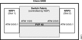
In this example, two NRPs are configured as Edge LSRs in the same Cisco 6400. The Edge LSRs are connected to each other via a PVP through the switch fabric of the Cisco 6400, as shown in Figure 1.
The following example shows the configuration for NRP1 in Slot 1:
The following example shows the configuration for NRP2 in Slot 2:
To complete the PVP connection between NRP1 and NRP2 in Figure 1, the NSP must be configured to set the path through the switch fabric. The following example shows the VP-switch configuration for the NSP:
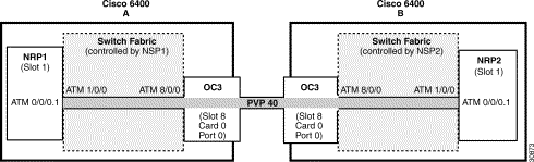
In this example, two NRPs are configured as Edge LSRs in the separate Cisco 6400s. The Edge LSRs are connected to each other via a PVP through the MPLS network, as shown in Figure 2.
The following example shows the configuration for NRP1 in Slot 1 of Cisco 6400 A:
The following example shows the configuration for NRP2 in Slot 1 of Cisco 6400 B:
To complete the PVP connection between NRP1 and NRP2 in Figure 1, the NSPs must be configured to set the path through the switch fabric and node line cards (NLCs).
The following example shows the VP-switch configuration for NSP1 in Cisco 6400 A:
The following example shows the VP-switch configuration for NSP2 in Cisco 6400 B:
In addition to providing transparent NSP redundancy, configuring a VPI Range to connect two MPLS Edge LSRs enable you to accommodate a large number of LVCs. For more information on VPI ranges, see the "Configuring a VPI Range" section of the ATM Switch Router Software Configuration Guide .
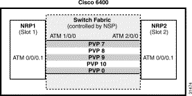
In this example, two NRPs are configured as Edge LSRs in the same Cisco 6400. The Edge LSRs are connected to each other via a VPI range through the switch fabric of the Cisco 6400, as shown in Figure 3.
The following example shows the configuration for NRP1 in Slot 1:
The following example shows the configuration for NRP2 in Slot 2:
To complete the VPI range connection between NRP1 and NRP2 in Figure 1, the NSP must be configured to set the paths through the switch fabric. PVP 0 is used to set up the control channels. The following example shows the VP-switch configuration for the NSP:
|
Note This example uses the default control channel PVC 0/32. You can also use a channel within the configured VPI range by using the tag-switching atm control-vc interface configuration command on the NRPs. For example, if you want to use the control channel PVC 7/32, then enter tag-switching atm control-vc 7 32 on both NRP1 and NRP2. |
In this example, two NRPs are configured as Edge LSRs in the separate Cisco 6400s. The Edge LSRs are connected to each other via a VPI range through the MPLS network, as shown in Figure 4.

The following example shows the configuration for NRP1 in Slot 1 of Cisco 6400 A:
The following example shows the configuration for NRP2 in Slot 1 of Cisco 6400 B:
To complete the VPI range connection between NRP1 and NRP2 in Figure 1, the NSPs must be configured to set the path through the switch fabric and node line cards (NLCs). PVP 0 is used to set up the control channels.
The following example shows the VP-switch configuration for NSP1 in Cisco 6400 A:
The following example shows the VP-switch configuration for NSP2 in Cisco 6400 B:
|
Note This example uses the default control channel PVC 0/32. You can also use a channel within the configured VPI range by using the tag-switching atm control-vc interface configuration command on the NRPs. For example, if you want to use the control channel PVC 7/32, then enter tag-switching atm control-vc 7 32 on both NRP1 and NRP2. |
The recommended method of using a Cisco 6400 to connect an ATM LSR to an MPLS Edge LSR is to configure the NSP as a virtual path (VP) switch. This configuration is also recommended for an NSP connecting two MPLS Edge LSRs.
The VP switch configuration provides NSP redundancy at the ATM layer. An NSP failure and the switchover to the redundant NSP is transparent to MPLS devices connected to the VP switch NSP.
| Step | Command | Task |
|---|---|---|
Create a PVP to another interface. Note You must use matching VPI values on the VP ends. |
To configure the NSP as a VP switch, follow these steps starting in global configuration mode:
The following example shows how to configure the NSP as a VP switch between an ATM interface at 1/0/0 and an ATM interface at 5/0/0. Both VPI values are 1.
Virtual Private Networks (VPNs) provide the appearance, functionality, and usefulness of a dedicated private network. The VPN feature for MPLS allows a Cisco IOS network to deploy scalable IPv4 Layer 3 VPN backbone service with private addressing, controlled access, and service-level guarantees between sites.
VPNs create a private network environment within the public infrastructure. A service provider can use VPNs to target a given clientele and deliver individualized private network services to that clientele in a secure IP environment by using the public infrastructure.
For an overview of MPLS VPN and its benefits, refer to the MPLS Virtual Private Networks feature module.
For general MPLS VPN configuration tasks, examples, and command references, see the MPLS Virtual Private Networks feature module.
In addition to these configurations, you must configure the NSP to create paths through the switch fabric of the Cisco 6400. The switch fabric provides connectivity between the NRPs and the external ports on the node line cards (NLCs). For general configuration tasks, examples, and command references for configuring paths through the switch fabric, see the "Configuring Virtual Connections" chapter of the ATM Switch Router Software Configuration Guide .
The examples in this section illustrate the configurations necessary to enable MPLS VPN on a Cisco 6400.
This section presents a basic Cisco 6400 MPLS VPN configuration. As shown in Figure 5, three customer edge (CE) routers are connected to the service provider backbone through three provider edge (PE) routers. Two of the PE routers are NRPs in the Cisco 6400, while the third PE router is a Cisco 7200. CE1 uses dual homing with PE1 and PE3.
CE1 and CE2 are devices in VPN1, while CE3 is in VPN2. PE1, or NRP1 in the Cisco 6400, handles the CE1 portion of VPN1. PE2, or NRP2 in the Cisco 6400, handles VPN2 as well as the CE2 portion of VPN1.

To enable a Cisco 6400 NRP to participate in a VPN, you must configure the NSP to create paths from the NRP through the Cisco 6400 switch fabric. The switch fabric provides the only connection between the NRP and an external port on a network line card (NLC). The switch fabric also provides the only connection between NRPs in the same Cisco 6400. Figure 6 shows a detailed schematic of the configuration used in the topology shown in Figure 5.
As shown in the accompanying configurations, you can use routed (in compliance with RFC 1483) PVCs for the CE to PE connections, as long as the CE router is capable of performing routing in compliance with RFC 1483 (aal5snap).
|
Note Each NRP in a Cisco 6400 is capable of handling multiple VPNs. |
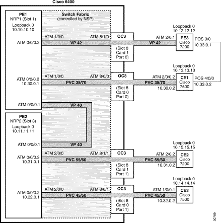
PE1 in Figure 6 is connected to PE3, via VP 42, and CE1, via PVC 35/70. In addition, PE1 and PE2, both NRPs in the same Cisco 6400, are connected to each other via VP40.
The following example shows the complete configuration for PE1 (Cisco 6400 NRP1):
PE2 in Figure 6 is connected to CE2, via PVC 55/60, and CE3, via PVC 45/50. In addition, PE1 and PE2, both NRPs in the same Cisco 6400, are connected to each other via VP40.
The following example shows the complete configuration for PE2 (Cisco 6400 NRP2):
The following example shows the configuration necessary for the PE Cisco 6400 NSP to create the paths in the switch fabric between the NRPs and the OC3 line cards shown in Figure 6.
PE3 in Figure 6 is connected to PE1, via VP 42, and CE1, via a packet over SONET (POS) link.
The following example shows the complete configuration for PE3 (Cisco 7200):
CE1 in Figure 6 is connected to PE1, via PVC 35/70, and PE3, via a packet over SONET (POS) link.
The following example shows the configuration for CE1 (Cisco 7500):
CE2 in Figure 6 is connected to PE2, via PVC 55/60.
The following example shows the configuration for the CE2 (Cisco 7200):
CE3 in Figure 6 is connected to PE2, via PVC 45/50.
The following example shows the configuration for CE3 (Cisco 7500):
Split horizon is disabled by default on ATM interfaces. If you are running RIP in your VPNs, you must enable split horizon.
The following example shows a typical configuration for an ATM subinterface on an NRP:
This section defines words, acronyms, and actions that appear throughout this document.
BGP—Border Gateway Protocol. Interdomain routing protocol that exchanges reachability information with other BGP systems. It is defined in RFC 1163.
Border Gateway Protocol—See BGP.
CEF—Cisco Express Forwarding. An advanced Layer 3 IP switching technology. CEF optimizes network performance and scalability for networks with large and dynamic traffic patterns.
CE router—Customer edge router. A router that is part of a customer network and that interfaces to a provider edge (PE) router.
Cisco Express Forwarding—See CEF.
CoS—Class of Service. A feature that provides scalable, differentiated types of service across a tag switched network.
Customer edge router—See CE router.
Edge LSR—Edge Label Switch Router. The role of an Edge LSR is to turn unlabeled packets into labeled packets, and vice versa. The Cisco 6400 can perform this function. (Formerly referred to as Tag Edge Router [TER].)
Generic routing encapsulation—See GRE.
GRE—Generic routing encapsulation. A tunneling protocol developed by Cisco that can encapsulate a wide variety of protocol packet types inside IP tunnels, creating a virtual point-to-point link to Cisco routers at remote points over an IP internetwork. By connecting multiprotocol subnetworks in a single-protocol backbone environment, IP tunneling that uses GRE allows network expansion across a single-protocol backbone environment.
IGP—Interior Gateway Protocol. An Internet protocol used to exchange routing information within an autonomous system. Examples of common IGPs include IGRP, OSPF, and RIP.
Interior Gateway Protocol—See IGP.
IS-IS—Intermediate system-to-intermediate system. OSI link-state hierarchical routing protocol in which ISs (routers) exchange routing information based on a single metric in order to determine network topology.
Label Distribution Protocol—See LDP.
Label Switch Controller—See LSC.
Label virtual circuit—See LVC.
LDP—Label Distribution Protocol. A standard protocol between MPLS enabled routers to negotiate the labels (addresses) used to forward packets. This protocol is not supported in Cisco IOS Release 12.0, and therefore is not used for this project. Cisco's proprietary version of this protocol is the TDP (Tag Distribution Protocol).
Link-state advertisement—See LSA.
LSA—Link-state advertisement. A broadcast packet used by link-state protocols. The LSA contains information about neighbors and path costs and is used by the receiving router to maintain a routing table.
LSC—Label Switch Controller. The role of an LSC is to create cross connects in an ATM switch so that labeled packets are forwarded through the switch, formerly referred to as Tag Switch Controller, or TSC.
LSR—Label Switch Router. The role of an LSR is to forward packets in an MPLS network by looking only at the fixed-length label.
MPLS—Multiprotocol Label Switching. MPLS forwards IP traffic using a label. This label instructs the routers and switches in the network where to forward the packets based on pre-established IP routing information.
Multiprotocol Label Switching—See MPLS.
NLRI—Network Layer Reachability Information. BGP sends routing update messages containing NLRI to describe a route and how to get there. In this context, an NLRI is a prefix. A BGP update message carries one or more NLRI prefixes and the attributes of a route for the NLRI prefixes; the route attributes include a BGP next hop gateway address, community values, and other information.
PE router—Provider edge router. A router that is part of a service provider's network and that is connected to a customer edge (CE) router.
Provider edge router—See PE router.
RD—Route distinguisher. An 8-byte value that is concatenated with an IPv4 prefix to create a unique VPN IPv4 prefix.
RIP—Routing Information Protocol. Used to exchange routing information within an autonomous system, RIP uses hop count as a routing metric.
SONET—Synchronous Optical Network. High-speed (up to 2.5 Gbps) synchronous network specification developed by Bellcore and designed to run on optical fiber. Approved as an international standard in 1988.
Synchronous Optical Network—See SONET.
TSP—Tag-switched path. A sequence of hops (R0...Rn) in which a packet travels from R0 to Rn through MPLS mechanisms. A tag-switched path can be established dynamically, based on normal routing mechanisms, or through configuration.
TSR—Tag Switching Router. A Layer 3 router that forwards a packet based on the value of a tag encapsulated in the packet.
TSP tunnel—A configured connection between two routers, in which MPLS is used to carry the packet.
TDP—Tag Distribution Protocol. Cisco's proprietary version of the LDP. This protocol is used in Cisco IOS Release 12.0 for label (that is, "tag") distribution.
traffic engineering—The techniques and processes used to cause routed traffic to travel through the network on a path other than the one that would have been chosen if standard routing processes had been used.
traffic engineering tunnel—A tag-switched path tunnel that is used for engineering traffic. It is set up through means other than normal Layer 3 routing and is used to direct traffic over a path different from the one that Layer 3 routing would cause it to take.
Tunneling—Architecture providing the services necessary to implement any standard point-to-point data encapsulation scheme.
VC—Virtual channel. Logical circuit created to ensure reliable communication between two network devices. A virtual channel is defined by a VPI/VCI pair, and can be either permanent (PVC) or switched (SVC). In Frame Relay and X.25, a virtual channel is called a virtual circuit. Sometimes abbreviated VC.
VCI—Virtual channel identifier. This is a 16-bit field in the header of an ATM cell. The VCI, together with the VPI, is used to identify the next destination of a cell as it passes through a series of ATM switches on its way to its destination.
Virtual channel identifier—See VCI.
Virtual path identifier—See VPI.
Virtual private network—See VPN.
Virtual Switch Interface—See VSI.
Virtual Trunk—A portion of a physical interface that has the following characteristics: Address space containing only one VPI and all VCIs underneath, bandwidth that is rate limited by hardware (VI), and ownership by a controller that uses it to interface to another peer controller.
VP—Virtual path. One of two types of ATM circuits identified by a VPI. A virtual path is a bundle of virtual channels, all of which are switched transparently across an ATM network based on a common VPI.
VPI—Virtual path identifier. 8-bit field in the header of an ATM cell. The VPI, together with the VCI, is used to identify the next destination of a cell as it passes through a series of ATM switches on its way to its destination.
VPN—Virtual private network. A secure IP-based network that shares resources with one or more physical networks. A VPN can contain one or more geographically dispersed sites that can communicate securely over a shared backbone.
VPN routing/forwarding instance—See VRF.
vpnv4—Used as a keyword in commands to indicate VPN-IPv4 prefixes. These prefixes are customer VPN addresses, each of which has been made unique by the addition of an 8-byte route distinguisher.
VRF—A VPN routing/forwarding instance. A VRF consists of an IP routing table, a derived forwarding table, a set of interfaces that use the forwarding table, and a set of rules and routing protocols that determine what goes into the forwarding table. In general, a VRF includes the routing information that defines a customer VPN site that is attached to a PE router.
VSI—Virtual Switch Interface. A protocol that allows for a common control interface to some of Cisco's ATM switches, for example, the MGX 8850 and BPX products.
Cisco Connection Online (CCO) is Cisco Systems' primary, real-time support channel. Maintenance customers and partners can self-register on CCO to obtain additional information and services.
Available 24 hours a day, 7 days a week, CCO provides a wealth of standard and value-added services to Cisco's customers and business partners. CCO services include product information, product documentation, software updates, release notes, technical tips, the Bug Navigator, configuration notes, brochures, descriptions of service offerings, and download access to public and authorized files.
CCO serves a wide variety of users through two interfaces that are updated and enhanced simultaneously: a character-based version and a multimedia version that resides on the World Wide Web (WWW). The character-based CCO supports Zmodem, Kermit, Xmodem, FTP, and Internet e-mail, and it is excellent for quick access to information over lower bandwidths. The WWW version of CCO provides richly formatted documents with photographs, figures, graphics, and video, as well as hyperlinks to related information.
You can access CCO in the following ways:
For a copy of CCO's Frequently Asked Questions (FAQ), contact cco-help@cisco.com. For additional information, contact cco-team@cisco.com.
|
Note If you are a network administrator and need personal technical assistance with a Cisco product that is under warranty or covered by a maintenance contract, contact Cisco's Technical Assistance Center (TAC) at 800 553-2447, 408 526-7209, or tac@cisco.com. To obtain general information about Cisco Systems, Cisco products, or upgrades, contact 800 553-6387, 408 526-7208, or cs-rep@cisco.com. |
Cisco documentation and additional literature are available in a CD-ROM package, which ships with your product. The Documentation CD-ROM, a member of the Cisco Connection Family, is updated monthly. Therefore, it might be more current than printed documentation. To order additional copies of the Documentation CD-ROM, contact your local sales representative or call customer service. The CD-ROM package is available as a single package or as an annual subscription. You can also access Cisco documentation on the World Wide Web at http://www.cisco.com, http://www-china.cisco.com, or http://www-europe.cisco.com.
If you are reading Cisco product documentation on the World Wide Web, you can submit comments electronically. Click Feedback in the toolbar and select Documentation. After you complete the form, click Submit to send it to Cisco. We appreciate your comments.
This document is to be used in conjunction with the Cisco 6400 UAC Hardware Installation and Maintenance Guide and the Cisco 6400 UAC Software Configuration Guide publications.
Access Registrar, AccessPath, Any to Any, AtmDirector, Browse with Me, CCDA, CCDE, CCDP, CCIE, CCNA, CCNP, CCSI, CD-PAC, the Cisco logo, Cisco Certified Internetwork Expert logo, CiscoLink, the Cisco Management Connection logo, the Cisco NetWorks logo, the Cisco Powered Network logo, Cisco Systems Capital, the Cisco Systems Capital logo, Cisco Systems Networking Academy, the Cisco Systems Networking Academy logo, the Cisco Technologies logo, ConnectWay, Fast Step, FireRunner, Follow Me Browsing, FormShare, GigaStack, IGX, Intelligence in the Optical Core, Internet Quotient, IP/VC, Kernel Proxy, MGX, MultiPath Data, MultiPath Voice, Natural Network Viewer, NetSonar, Network Registrar, the Networkers logo, Packet, PIX, Point and Click Internetworking, Policy Builder, Precept, ScriptShare, Secure Script, ServiceWay, Shop with Me, SlideCast, SMARTnet, SVX, The Cell, TrafficDirector, TransPath, ViewRunner, Virtual Loop Carrier System, Virtual Service Node, Virtual Voice Line, VisionWay, VlanDirector, Voice LAN, WaRP, Wavelength Router, Wavelength Router Protocol, WebViewer, Workgroup Director, and Workgroup Stack are trademarks; Changing the Way We Work, Live, Play, and Learn, Empowering the Internet Generation, The Internet Economy, and The New Internet Economy are service marks; and ASIST, BPX, Catalyst, Cisco, Cisco IOS, the Cisco IOS logo, Cisco Systems, the Cisco Systems logo, the Cisco Systems Cisco Press logo, Enterprise/Solver, EtherChannel, EtherSwitch, FastHub, FastLink, FastPAD, FastSwitch, GeoTel, IOS, IP/TV, IPX, LightStream, LightSwitch, MICA, NetRanger, Post-Routing, Pre-Routing, Registrar, StrataView Plus, Stratm, TeleRouter, and VCO are registered trademarks of Cisco Systems, Inc. or its affiliates in the U.S. and certain other countries. All other trademarks mentioned in this document are the property of their respective owners. The use of the word partner does not imply a partnership relationship between Cisco and any of its resellers. (9912R)
Copyright © 2000, Cisco Systems, Inc.
All rights reserved.
![]()
![]()
![]()
![]()
![]()
![]()
![]()
![]()
Posted: Wed Apr 2 09:41:12 PST 2003
All contents are Copyright © 1992--2002 Cisco Systems, Inc. All rights reserved.
Important Notices and Privacy Statement.