|
|

Table Of Contents
Planning for Cisco Emergency Responder 2.0
Understanding Enhanced 911 (E911)
Overview of Enhanced 911 Requirements
Understanding E911 and Cisco Emergency Responder Terminology
Understanding Cisco Emergency Responder
Cisco Emergency Responder 2.0 Features
Network Hardware and Software Requirements
Licenses for Cisco Emergency Responder 2.0
How Cisco Emergency Responder Fits Into Your Network
What Happens When an Emergency Call Is Made
Understanding Cisco Emergency Responder Clusters and Groups
Determining the Required Number of Cisco Emergency Responder Groups
Data Integrity and Reliability Considerations
Preparing Your Network For Cisco Emergency Responder
Obtain CAMA or PRI Trunks to the PSTN
Obtain DID Numbers from Your Service Provider
Negotiate ALI Submission Requirements With Your Service Provider
Preparing Your Staff for Cisco Emergency Responder
Deploying Cisco Emergency Responder
Deploying Cisco Emergency Responder in One Main Site with One PSAP
Deploying Cisco Emergency Responder in One Main Site with Two or More PSAPs
Deploying Cisco Emergency Responder In One Main Site with Satellite Offices
Deploying Cisco Emergency Responder In Two Main Sites
Planning for Cisco Emergency Responder 2.0
Cisco Emergency Responder Administration Guide 2.0 (Cisco ER) helps you manage emergency calls in your telephony network so that you can respond to these calls effectively and so that you can comply with local ordinances concerning the handling of emergency calls. In North America, these local ordinances are called "enhanced 911," or E911. Other countries and locales might have similar ordinances.
Because emergency call ordinances can differ from location to location within a country, region, state, or even metropolitan area, Cisco ER includes the flexibility you need to fit your emergency call configuration to specific local requirements. However, because ordinances do differ from location to location, and because security requirements differ from company to company, you need to do extensive planning and research before you can deploy Cisco ER in a manner that fits your legal and security needs.
These topics help you understand emergency call ordinances, how Cisco ER helps you meet the ordinances, and what you need to do to deploy Cisco ER successfully:
•
Understanding Enhanced 911 (E911)
•
•
•
•
Understanding Enhanced 911 (E911)
Enhanced 911, or E911, is an extension of the basic 911 emergency call standard in North America. These topics describe E911 requirements and terminology.
•
•
Overview of Enhanced 911 Requirements
Enhanced 911 (E911) extends the basic 911 emergency call standard to make it more reliable.
When using basic 911 in North America, if a caller dials 911, the call is routed to a Public Safety Answering Point (PSAP), also called the 911 operator. The PSAP is responsible for talking to the caller and arranging the appropriate emergency response, such as sending police, fire, or ambulance teams.
E911 extends this standard with these requirements:
•
•
In E911, the location of the caller is determined by the Emergency Location Identification Number (ELIN), which is a phone number the PSAP can dial to reconnect to the emergency caller if the emergency call is cut off for any reason, or if the PSAP simply needs to talk to the caller again. The emergency call is routed to the PSAP based on the location information associated with this number. For multi-line phone systems, such as an office system, the ELIN can be associated with more than one telephone by grouping the phones in an Emergency Response Location (ERL). In this case, the location the PSAP receives would be the address of an office building. For large buildings, the location would include additional information such as floor or region on a floor. Each ERL requires a unique ELIN.
In addition to these general E911 requirements, each locality can further extend or limit these requirements. For example, a city ordinance might include specific limitations on the size of an ERL (such as, no larger than 7,000 square feet), or on the number of phones that can be included in an ERL (such as, no more than 48 phones). You must work with your service provider and local government to determine the exact E911 requirements in your area.
Related Topics
•
•
Understanding E911 and Cisco Emergency Responder Terminology
Table 1-1 defines some of the key terminology used in this document.
Table 1-1 E911 and Cisco Emergency Responder Terminology
ALI
Automatic location information. Information that ties an ELIN to a location, is used to route emergency calls from that ELIN to the correct local PSAP, and is presented to the PSAP to help the PSAP locate the emergency caller. In Cisco ER, you fill in ALI data for each ERL and submit the ALI data to your service provider for inclusion in the ALI database.
ANI
Automatic number identification. ANI is another name for ELIN. This document uses ELIN instead of ANI.
CAMA
Centralized automated message accounting. An analog phone trunk that connects directly to an E911 selective router, bypassing the Public Switched Telephone Network (PSTN).
DID
Direct inward dial. A telephone number obtained from your service provider that can be used to dial into your telephone network. DID numbers are used for ELIN.
ELIN
Emergency location identification number. A phone number that routes the emergency call to the local PSAP, and which the PSAP can use to call back the emergency caller. The PSAP might need to call the number if the emergency call is cut off, or if the PSAP needs additional information after normally ending the emergency call. See ALI.
emergency call
A call made to the local emergency number, such as 911. Cisco ER routes the call to the service provider's network, where the call is routed to the local PSAP.
emergency caller
The person who places the emergency call. The caller might require help for a personal emergency, or might be reporting a more general emergency (fire, theft, accident, and so forth).
ERL
Emergency response location. The area from which an emergency call is placed. The ERL is not necessarily the location of the emergency. If an emergency caller is reporting a general emergency, the actual emergency might be in a different area. In Cisco ER, you assign switch ports and phones to ERLs, and ERL definitions include ALI data.
ESN
Emergency service number.
ESZ
Emergency service zone. The area covered by a given PSAP. This area usually includes several police and fire departments. For example, a city and its suburbs might be serviced by one PSAP.
Each ESZ is assigned a unique ESN to identify it.
MSAG
Master street address guide. A database of ALIs that enables proper routing of emergency calls to the correct PSAP. In Cisco ER, you export your ALI definitions and transmit them to your service provider, who ensures the MSAG is updated. You must negotiate this service with your service provider—it is not a service provided directly through Cisco ER.
NENA
National Emergency Number Association. The organization that recommends data and file formats for ALI definitions and other emergency call requirements in the United States. Cisco ER uses the NENA formats for ALI data export files. Your service provider might have additional restrictions on data format, so ensure that your ALI entries abide by your service provider's rules.
PSAP
Public safety answering point. The PSAP is the organization that receives emergency calls (for example, the 911 operator) and is staffed by people trained in handling emergency calls. The PSAP talks to the emergency caller and notifies the appropriate public service organizations (such as police, fire, or ambulance) of the emergency and its location.
Related Topics
•
•
Understanding Cisco Emergency Responder
These topics provide an overview of Cisco Emergency Responder and how you can use it in your network.
•
•
•
•
•
•
•
•
Cisco Emergency Responder 2.0 Features
These are the major new and enhanced features of Cisco Emergency Responder (Cisco ER) 2.0:
•
•
•
•
•
•
•
•
•
•
See the Release Notes for Cisco Emergency Responder 2.0 for a list of hardware and software supported in Cisco ER 2.0.
Related Topics
•
•
•
•
•
•
Network Hardware and Software Requirements
Cisco ER 2.0 supports a variety of hardware and software components. For the complete list of supported hardware and software, see the Release Notes for Cisco Emergency Responder 2.0.
Licenses for Cisco Emergency Responder 2.0
Cisco ER 2.0 uses a web-based system for requesting, creating, and delivering product licenses. Once you register your Cisco ER product through the Cisco.com website, a file containing the server license will be sent to you as a text-file email attachment.
This section describes the following topics:
•
•
Licenses for Initial Installation
Cisco ER 2.0 does not require a license key for initial installation. Unlicensed Cisco ER 2.0 software will operate normally for 60 days after it is installed, with a capacity of 100 phones. Additional user licenses are not effective until a server license is installed. If you do not install a server license within 60 days, the Cisco ER 2.0 system shuts down.
Migrating Licenses
When migrating from Cisco ER 1.3 to Cisco ER 2.0, you will need to order upgraded licenses using the procedures given later in this section. Existing Cisco ER 1.3 licenses cannot be converted to Cisco ER 2.0 licenses.
Uploading License Files
You can upload license files to the Cisco ER servers using the Cisco ER Administration web interface. To do so, follow these steps:
Procedure
Step 1
Step 2
Step 3
Step 4
Step 5
Step 6
Related Topics
Server Licenses
You must purchase a server license for each Cisco ER server in a server group. Each server license includes an implicit user license for 100 users.
To order Cisco ER server licenses, follow these steps:
Procedure
Step 1
Step 2
To obtain the MAC address of the server, follow these steps:
a.
b.
c.
After processing, you will receive the server license file as a text-file email attachment.
Step 3
Step 4
User Licenses
Each Cisco ER server license includes 100 user licenses. User licenses are shared by both primary and secondary Cisco ER servers irrespective of where they are installed.
The total number of user licenses available in a server group at any given time is the sum of the user licenses available on both servers in the server group.
To order additional or upgraded Cisco ER user licenses, perform these steps:
Procedure
Step 1
Step 2
After processing, you will receive the user license as a text-file email attachment.
Step 3
Step 4
Determining Your License Requirements
For server licenses:
•
•
For user licenses:
•
•
•
Example
If your Cisco ER configuration supports 500 users, you need to purchase:
•
•
•
How Cisco Emergency Responder Fits Into Your Network
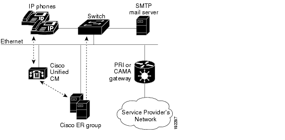
Figure 1-1 shows how Cisco Emergency Responder (Cisco ER) fits into your network.
Figure 1-1 How Cisco ER Fits Into Your Network
Cisco ER depends on Cisco Unified Communications Manager for the corporate dial plan, which you must modify to send emergency calls to the Cisco ER group. See Chapter 3, "Configuring Cisco Unified CallManager 4.2 and 4.3 for Cisco Emergency Responder 2.0" or "Configuring Cisco Unified Communications Manager 5.0, 5.1, and 6.0 for Cisco Emergency Responder 2.0," for complete information about the required Cisco Unified Communications Manager configuration.
To track phones, Cisco ER queries Cisco Unified Communications Manager for a list of phones registered with the cluster. Then, Cisco ER queries the switches on the network (the ones you have identified to Cisco ER) to determine the port to which the phones are connected. Cisco ER does this tracking at regular intervals during the day so that it can identify when a phone moves. See the "Configuring Switches for Cisco Emergency Responder" section on page 5-39 for more information about setting up switches for Cisco ER. See the "Managing Phones" section on page 5-47 for information on how to configure switch ports so that Cisco ER can send emergency calls to the correct PSAP based on port and phone location.
Optionally, you can have an SMTP email server in your network or with a service provider. You can configure Cisco ER to send email to your onsite alert (security) personnel to notify them of emergency calls. If the server is set up as an email-based paging service, the personnel are paged.
Finally, you need a gateway with a PRI or CAMA link to the service provider's network so that Cisco ER can route emergency calls to the local public safety answering point (PSAP).
Figure 1-1 shows one Cisco ER group supporting a single Cisco Unified Communications Manager cluster. You can support more than one Cisco Unified Communications Manager cluster with a single Cisco ER group, as long as the Cisco Unified Communications Managers are running the same software version. If you have a larger network, you can install multiple Cisco ER groups and create a Cisco ER cluster. See the "Understanding Cisco Emergency Responder Clusters and Groups" section for a discussion of this more complex installation.
See the "What Happens When an Emergency Call Is Made" section for an explanation of the path an emergency call takes when managed by Cisco ER.
Related Topics
•
•
•
What Happens When an Emergency Call Is Made
This topic describes the process Cisco Emergency Responder (Cisco ER) uses to handle emergency calls. Understanding this process can help you set up Cisco ER correctly and troubleshoot problems you might encounter.
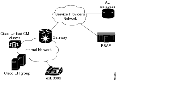
Figure 1-2 illustrates how Cisco ER routes an emergency call.
Figure 1-2 How Cisco Emergency Responder Routes Emergency Calls
When someone uses extension 3003 to make an emergency call:
1.
2.
3.
4.
5.
6.
7.
To ensure proper performance and eliminate major points of failure, verify the following:
•
•
Work with your service provider to determine how many gateways you need and where to connect them. These requirements are based on the service provider's network topology more than on your network's topology. In the United States, the emergency call network is tandem to the PSTN, so simply connecting to the PSTN does not ensure the correct routing of emergency calls.
•
•
Cisco Emergency Responder's Call Routing Order
Cisco ER directs emergency calls based on the location of the phone from which the call is placed. The location of the phone is determined by the following methods, in order of precedence:
•
•
•
•
•
•
•
Note
Customers should resolve problems that prevent IP phones from being tracked by MAC or IP address (see the "Too Many Unlocated Phones" section) so that IP phones will be not removed from the Unlocated Phones page. An ERL may be assigned directly to an IP phone on the Unlocated Phones page, but this assignment will not take effect if the phone is assigned a location by manual line number configuration. Use the ERL Debug Tool to determine the ERL assignment in effect for an IP phone that appears on the Unlocated Phones page.
Identifying Unlocated Phones
Cisco ER defines unlocated phones as those Cisco Unified IP Phones which meet all of the criteria below:
•
•
•
•
Note
Assigning ERLs to Unlocated Phones
Cisco ER provides a procedure to assign an ERL to IP phones that are displayed on the Unlocated Phones screen. This assignment associates the MAC address of the unlocated phone with an ERL that is selected by the administrator. These rules apply to this association:
•
•
For example, Phone A is currently unlocated and appears on the Unlocated Phones page. Using the ERL assignment feature for unlocated phones, Location A is assigned as the ERL for this phone. A subsequent phone tracking cycle finds Phone A behind a switch port and it no longer appears in the Unlocated Phones page. The Phone A-to-Location-A assignment is no longer valid. Because the association is persistent, if the IP phone is unlocated at any future time, the assignment will be valid.
Location Information for Calls Forwarded by CTI Applications
If emergency calls are forwarded to 911 by computer telephony integration (CTI) applications, such as Cisco Unity, then the location used for call routing and PSAP reporting will be the location of the application server, not the location of the original caller. This remains true even if the application retains the original calling line number, as is made possible in Cisco Unified CallManager 4.2(3) and 4.3, and in Cisco Unified Communications Manager 5.1 and 6.0. For this reason, you should dial 911 directly.
Related Topics
•
•
•
•
•
•
Understanding Cisco Emergency Responder Clusters and Groups
Deploy Cisco Emergency Responder (Cisco ER) in your network as a pair of redundant servers. One server is designated as the Publisher server and the other as the Subscriber server. Each Cisco ER Publisher server and Subscriber server make up a Cisco ER Server Group. Configuration data for the server groups is stored in a database on the Publisher. This data is replicated to the Subscriber.
A Cisco ER cluster is a set of Cisco ER server groups that share data to provide correct emergency call handling capabilities. Cisco ER cluster information is stored in a central location in the cluster called the cluster database. A Cisco ER server group is considered part of a cluster when the group points to the same cluster database as the other server groups in that cluster.
Cisco ER 2.0 uses two separate databases:
•
•
During installation, both databases are created on each Cisco ER server. However, only one Cisco ER server contains cluster data.
Note
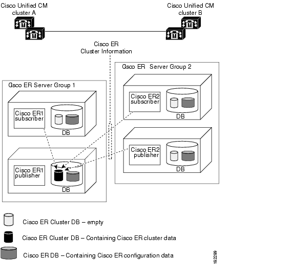
Figure 1-3 shows how Cisco Emergency Responder (Cisco ER) groups can be joined in a single Cisco ER cluster.
Figure 1-3 Understanding the Relationship between Cisco ER Groups and Cisco ER Clusters
In this example:
•
•
•
•
•
Note
Note
To complete the creation of the Cisco ER cluster, you must create inter-cluster trunks and route patterns to allow the Cisco ER groups to hand off emergency calls between the groups (see the "Creating Route Patterns for Inter-Cisco Emergency Responder-Group Communications" section) and configure these route patterns in Cisco ER (see the "Configuring Group Telephony Settings For the Cisco Emergency Responder Server" section on page 5-18).
Caution
Moving Phone Between Clusters
The following scenario illustrates how Cisco ER treats phones moving between clusters:
•
–
–
•
–
–
•
–
–
•
Be aware of the following when planning your Cisco ER system:
•
However, a Cisco ER cluster can contain Cisco ER groups that support different versions of Cisco Unified Communications Manager. In this way, Cisco ER can support a mix of Cisco Unified Communications Manager versions in your telephony network.
•
Related Topics
•
•
Determining the Required Number of Cisco Emergency Responder Groups
To ensure efficient Cisco Emergency Responder (Cisco ER) performance, you should take the limits each Cisco ER group can support into account when planning your Cisco ER deployment. Keep in mind that a single Cisco Unified Communications Manager cluster can only be supported by one Cisco ER group, although a single Cisco ER group can support more than one Cisco Unified Communications Manager cluster.
Refer to the Release Notes for Cisco Emergency Responder 2.0 for the capacities of a single Cisco ER group with your configuration. Be aware that you might meet the maximum figures for one limitation without reaching the figures for another. For example, you might define 1,000 switches, but have fewer than 30,000 switch ports.
You can install additional groups to manage larger networks. Each Cisco ER group can work with one or more Cisco Unified Communications Manager clusters.
In addition to these per group limits, you must also consider the territories covered by the service provider's ALI database providers. If your network extends into more than one ALI database provider's territory, you should use the ALI Formatting Tool (AFT) to export ALI records in multiple ALI database formats.
To have a single Cisco ER group support multiple LECs, follow these steps:
Procedure
Step 1
Step 2
Step 3
Step 4
Step 5
If AFTs are not available for each LEC, you can achieve a similar result by editing the NENA-formatted files with a text editor.
Related Topics
•
•
•
•
•
•
Data Integrity and Reliability Considerations
The correct routing of emergency calls to the local PSAP is based on your ERL configuration. Inside your network, correct identification of the ERL for a phone determines which gateway is used to connect to the service provider's network. In the service provider's network, the routing is based on the ELIN, which is also used to look up the ALI for the caller. Thus, your ERL configuration must be reliable so that the correct ELIN is assigned to the emergency call.
These are the things to consider to maintain the reliability of your ERL configuration:
•
This type of change will not normally result in an incorrectly routed call, because it is unlikely that a single LAN switch will connect to ERLs serviced by separate PSAPs. However, the ALI sent will be incorrect, with the possibility that your security staff will search the third floor for an emergency when the caller is actually on the fourth floor.
To prevent this problem, ensure that your wiring closets are secure, and train your networking staff to avoid swapping wires between switch ports.
•
Note
•
Cisco ER 1.2 and later locates these phones as follows:
–
–
To determine the ERL that Cisco ER will use for call routing, use the ERL Debug Tool to search for the phone. The search yields the current ERL that will be used in routing the emergency call from this phone and also why Cisco ER chose that ERL. For more information, see the "Using the Cisco Emergency Responder Admin Utility" section.
•
•
Any phones connected to undefined switches are listed as unlocated phones in Cisco ER. If you changed a defined switch, new or changed ports become ports without any ERL association. You should assign ERLs for the new or changed switch ports. See the "Understanding the Network Administrator's Role" section and the "Understanding the ERL Administrator's Role" section for information on the recurring tasks involved in network changes.
•
Related Topics
•
•
•
•
Preparing Your Network For Cisco Emergency Responder
These topics describe the steps you should take to prepare your network before deploying Cisco Emergency Responder.
•
•
•
Obtain CAMA or PRI Trunks to the PSTN
To handle emergency calls, you must obtain PRI or CAMA trunks to connect to your service provider. Your service provider might support only one type of trunk. If you have an option, work with your service provider to decide on the type of connection that works best for you.
Consider these issues:
•
When you configure the PRI trunk, you must configure it so that it sends the actual calling party's number rather than a generic number (such as the main number of the site). Otherwise, the PSAP will not receive the expected ELIN, and the emergency call might not be routed to the right PSAP.
•
Work with your service provider to determine how many trunks are required for your network. For example, some service providers use a guideline of two CAMA trunks for 10,000 phones.
Also, the number of trunks can differ depending on the distribution of your offices with respect to the local PSAPs. For example, if you have offices in New York and Chicago, you would need trunks in both cities, even if your total number of telephones would require fewer trunks if your office was only in New York. Your service provider, who knows the layout of the emergency call network, can direct you on trunk requirements that are based on PSAP accessibility.
Related Topics
•
Obtain DID Numbers from Your Service Provider
You must obtain direct inward dial (DID) numbers from your service provider for use as emergency location identification numbers (ELIN) for your emergency response locations (ERL).
In general, you must have at least one unique number per ERL. Emergency calls are routed to the local PSAP based on the ELIN of the ERL, so if you do not have unique ELINs, the call cannot be routed properly. The ALI database provider also might not accept ALIs that include duplicate ELINs.
You might want to have more than one ELIN per ERL. If your ERLs include more than one phone, you might have more than one emergency call made from an ERL in a short time (less than three hours). If you assign only one ELIN to the ERL, that ELIN is reused for each emergency call. Thus, if four people make emergency calls in the space of an hour, if the PSAP calls the ELIN, the PSAP will connect to the last caller. This might be a problem if the PSAP was trying to contact one of the earlier callers.
If you define more than one ELIN per ERL, Cisco Emergency Responder (Cisco ER) uses those ELINs in sequence until all are used, then reuses the ELINs in order. Cisco ER maintains the link between the ELIN and the extension of the actual emergency caller for up to three hours.
Because you need to purchase these DIDs from your service provider, you must balance the needs of your budget with the needs of maintaining the capability of the PSAP to reach the correct caller.
Note
Related Topics
•
Negotiate ALI Submission Requirements With Your Service Provider
Emergency calls are routed to the appropriate PSAP based on the emergency location identification number (ELIN) of the emergency caller. To route the call, the telephony network must have your automatic location information (ALI) that maps these ELINs to a location. Besides routing the call appropriately, the ALI database also supplies the location information that appears on the PSAPs screens to help them locate the caller.
Cisco ER includes features to create ALIs and to export them in a variety of formats that should be acceptable to your service provider. After you create your ERL/ALI configuration, you must export the ALI data and send it to the ALI database provider.
How you send the data can vary from location to location or service provider to service provider. You must work with your service provider to determine the services you can select for submitting ALI data. At a minimum, you must know the data format they expect, and the transmission method they require.
Cisco ER does not include any automated capability for submitting ALIs.
Tip
Related Topics
•
•
•
Upgrade Switches and Phones
The most powerful capability of Cisco Emergency Responder (Cisco ER) is the ability to automatically track the addition or movement of telephones in your network. This dynamic capability helps ensure that emergency calls are routed to the local PSAP, even if a user moves a phone between cities. This can reduce the cost of maintaining your telephone network, simplifying moves, adds, or changes.
However, Cisco ER can only automatically track telephone movement for certain types of phones, and for phones attached to certain types of switch ports. See "Network Hardware and Software Requirements" section for a list of these phones and switches.
To achieve full automation, update your switches to supported models or software versions, and replace your telephones with supported models.
Related Topics
•
Preparing Your Staff for Cisco Emergency Responder
Cisco Emergency Responder (Cisco ER) does not replace your existing emergency procedures. Instead, Cisco ER is a tool you can use to augment those procedures. Before deploying Cisco ER, consider how it fits into your procedures and how you want to use the Cisco ER system's capabilities.
These are the main things to consider when deciding how to use Cisco ER:
•
•
•
Related Topics
•
•
•
•
Deploying Cisco Emergency Responder
These topics describe deployment models for various types of networks. You can use these examples as modules, combining them to form a larger, more complex network.
•
•
•
•
Deploying Cisco Emergency Responder in One Main Site with One PSAP
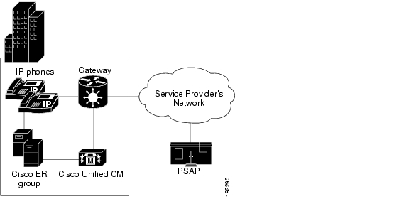
To support a simple telephony network consisting of a single Cisco Unified Communications Manager cluster, install two Cisco ER servers and configure one server as the Publisher and the other server as a Subscriber pointing to the Publisher.
Because there is only one local PSAP, you only need one gateway to the service provider's network, although capacity planning for your telephony network might require more than one gateway. Configure all route patterns to use this gateway.
Figure 1-4 shows how Cisco Emergency Responder (Cisco ER) fits into a simple telephony network where you have a single Cisco Unified Communications Manager cluster.
Figure 1-4 Deploying Cisco ER in One Main Site with One PSAP
See these examples to extend this example to more complex networks:
•
•
•
Related Topics
•
•
•
•
•
•
•
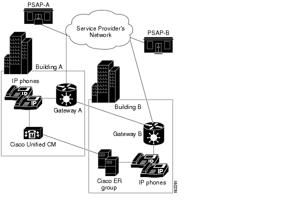
Deploying Cisco Emergency Responder in One Main Site with Two or More PSAPs
Figure 1-5 illustrates the Cisco Emergency Responder (Cisco ER) configuration if you have one main site that is served by two or more PSAPs. This example assumes you have one Cisco Unified Communications Manager cluster. If you have more than one, the setup is logically the same as the one discussed in the "Deploying Cisco Emergency Responder In Two Main Sites" section.
Figure 1-5 Deploying Cisco ER in One Main Site with Two or More PSAPs
To support this type of network, install two Cisco ER servers and configure one server as the Publisher and the other server as a Subscriber pointing to the Publisher.
Because there are two PSAPs serving the location, you probably need more than one gateway connecting to different parts of the service provider's network. However, this depends on the layout of the service provider's network: you might only need one gateway if the PSAPs are served by a selective router that can intelligently route emergency calls to more than one PSAP. Consult with your service provider to determine the requirements for your buildings. In this example, we assume you will need two gateways. Of course, capacity planning for your telephony network might require more than one gateway for each link.
After setting up the gateways to correctly connect to the service provider's network, configure all route patterns used in Building A ERLs to use gateway A, and all route patterns used in Building B ERLs to use gateway B. As phones move between buildings, Cisco ER dynamically updates their ERLs so that emergency calls get routed out of the desired gateway.
See these examples to extend this example to other networks:
•
•
•
Related Topics
•
•
•
•
•
•
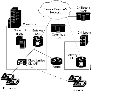
Deploying Cisco Emergency Responder In One Main Site with Satellite Offices
Figure 1-6 illustrates the Cisco Emergency Responder (Cisco ER) configuration if you have one main site that serves one or more satellite offices, that is, where the phones in the satellite office are run from the Cisco Unified Communications Manager cluster on the main site. If the satellite office has its own Cisco Unified Communications Manager cluster, see the "Deploying Cisco Emergency Responder In Two Main Sites" section.
Figure 1-6 Deploying Cisco ER in One Main Site with Satellite Offices
Caution
To support this type of network, install two Cisco ER servers and configure one server as the Publisher and the other server as a Subscriber pointing to the Publisher. Install both servers in the main office.
Most likely, there are separate PSAPs serving the main (Columbus) and satellite (Chillicothe) offices. Thus, you probably need more than one gateway connecting to different parts of the service provider's network (you might even have different service providers). However, this depends on the layout of the service provider's network: you might only need one gateway if the PSAPs are served by a shared switch. Consult with your service provider to determine the requirements for your buildings. In this example, we assume you will need two gateways. Of course, capacity planning for your telephony network might require more than one gateway for each link.
After setting up the gateways to correctly connect to the service provider's network, configure all route patterns used in Columbus's ERLs to use gateway COL, and all route patterns used in Chillicothe's ERLs to use gateway CHIL. As phones move between sites, Cisco ER dynamically updates their ERLs so that emergency calls get routed out of the desired gateway.
You might also need to tune SNMP performance to account for the WAN link. Cisco ER must do SNMP queries of the remote site's switches to track phone movements there, and you might run into SNMP time-out problems if you do not allow enough time or retries to make a successful SNMP query. See the "Configuring the SNMP Connection" section on page 5-39 for more information.
See these examples to extend this example to other networks:
•
•
•
Tip
Related Topics
•
•
•
•
•
•
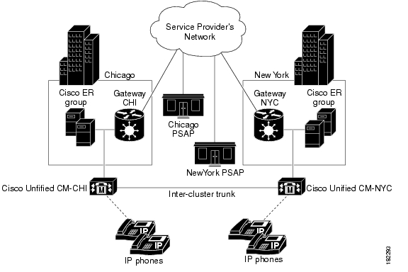
Deploying Cisco Emergency Responder In Two Main Sites
Figure 1-7 illustrates the Cisco Emergency Responder (Cisco ER) configuration if you have two (or more) main sites, each served by a separate PSAP.
Figure 1-7 Deploying Cisco ER in Two Main Sites
You can adapt this example to a more complex setup by combining this discussion with these examples:
•
If a main site is served by more than one PSAP, see the "Deploying Cisco Emergency Responder in One Main Site with Two or More PSAPs" section for information on deploying Cisco ER in that site.To support this type of network:
•
•
Most likely, there are separate PSAPs serving your main offices. In this example, Chicago and New York use different PSAPs. You need at least one gateway in Chicago, and one in New York, to connect to different parts of the service provider's network (you might even have different service providers). Consult with your service provider to determine the requirements for your buildings. Of course, capacity planning for your telephony network might require more than one gateway in each site.
After setting up the gateways to correctly connect to the service provider's network, configure all route patterns used in Chicago's ERLs to use gateway CHI, and all route patterns used in New York's ERLs to use gateway NYC.
To enable phone movement between Chicago and New York, you must also configure an inter-cluster trunk to link the Cisco Unified Communications Manager clusters, and create an inter-Cisco ER group route pattern so that Cisco ER can transfer calls between Cisco Unified Communications Manager clusters served by separate Cisco ER groups. The "Creating Route Patterns for Inter-Cisco Emergency Responder-Group Communications" section goes into more details about how Cisco ER handles phone movement in this situation.
As phones move between sites, Cisco ER dynamically updates their ERLs so that emergency calls get routed out of the desired gateway. However, if the WAN link becomes unavailable, Cisco ER can not track phone movement between the sites.
See these examples to extend this example to other networks:
•
•
•
Related Topics
•
•
•
•
•
•
•
![]()
![]()
![]()
![]()
![]()
![]()
![]()
![]()
Posted: Fri Jun 8 00:15:56 PDT 2007
All contents are Copyright © 1992--2007 Cisco Systems, Inc. All rights reserved.
Important Notices and Privacy Statement.