|
|

Table Of Contents
Cisco Systems Equipment Needed
Configuring the Lucent/Avaya Definity G3si PBX
Calling Name and Number Feature
Lucent/Avaya Definity G3si Software Release
Cisco 2621 Router Configuration
Application Note
Lucent/Avaya Definity G3si V7 PBX with CallManager using Cisco 2621-E1 PRI NET5 Gateway
This application note discusses the integration of the Lucent/Avaya Definity G3si V7 PBX with CallManager using the Cisco 2621-E1 PRI NET5 Gateway.
Integration Description
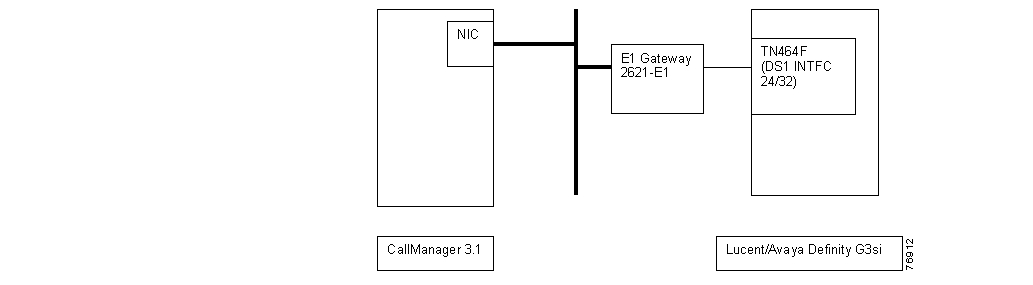
Connectivity is achieved by using the industry standard PRI protocol. The Lucent/Avaya Definity G3si can be configured as either the NETWORK or USER side. The figure below shows the general network layout for the integration.
Network Layout
Cisco Systems Equipment Needed
•
Hardware (Cisco 2621 Gateway): 2MFT E1 Port
•
PBX Requirements
•
•
Features
Key features supported:
•
•
Key features not supported:
•
•
Configuring the Lucent/Avaya Definity G3si PBX
To configure the Lucent/Avaya Definity G3si PBX, do the following:
Step 1.
Step 2.
Step 3.
Step 4.
Circuit Pack
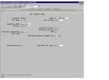
The following figures show the configuration of the DS1 circuit pack.
DS1 Circuit Pack
Signaling Group
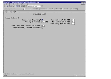
The following figure shows the configuration of the signaling group.
Signaling Group
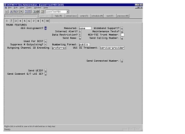
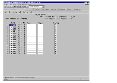
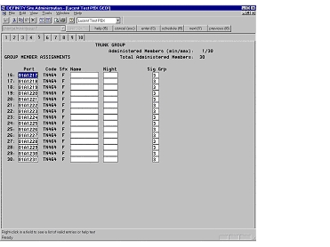
Trunk Group
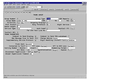
The following figures show the configuration of the trunk group.
Trunk Group
Trunk Group—Trunk Features
Trunk Group—Group Member Assignments
Trunk Group—Group Member Assignments Continued
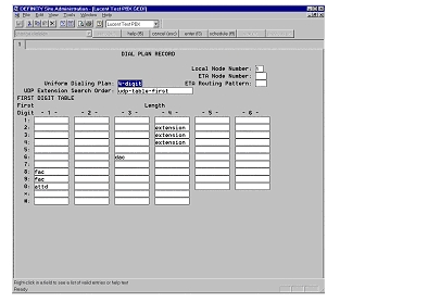
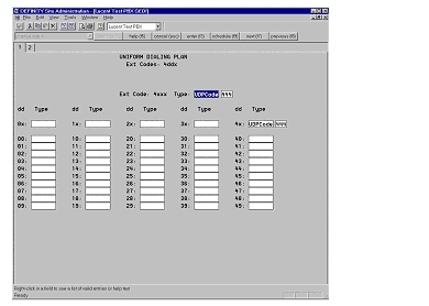
Uniform Dialing Plan
The following figures show the configuration of the uniform dialing plan.
Dial Plan Record
Uniform Dialing Plan
Configuring Cisco CallManager
To configure Cisco CallManager, do the following:
Step 1.
Step 2.
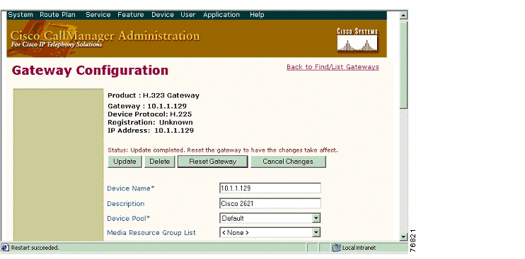
Gateway Configuration
The following figures show the configuration of the Cisco 2621 H.323 Gateway.
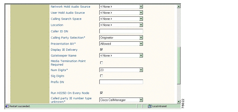
Cisco 2621 H.323 Gateway Configuration
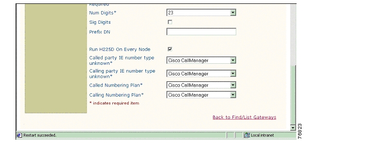
Cisco 2621 H.323 Gateway Configuration Continued
Cisco 2621 H.323 Gateway Configuration Continued
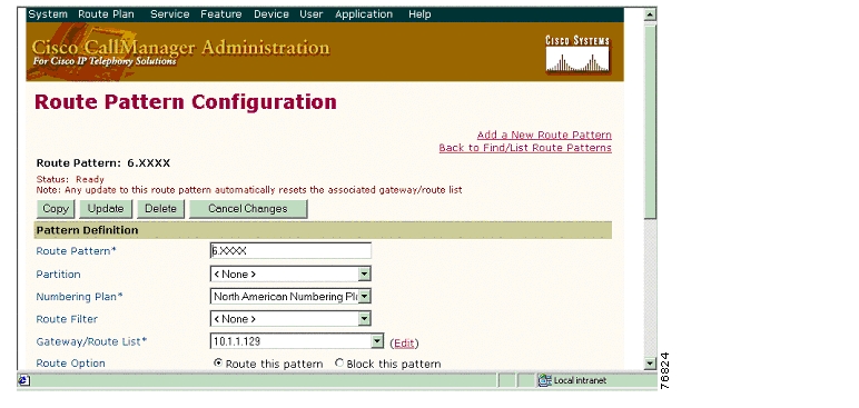
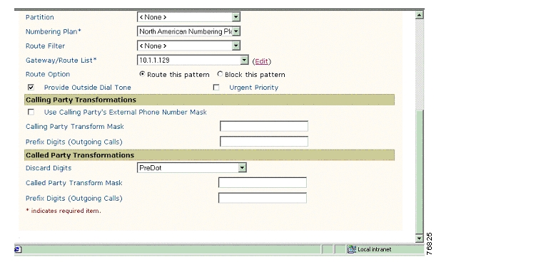
Route Pattern Configuration
The following figures show the configuration of the route pattern.
Route Pattern Configuration
Route Pattern Configuration Continued
Considerations
Calling Name and Number Feature
When calling from a Cisco 7960 IP phone to a Lucent/Avaya digital phone, the Lucent/Avaya phone displays the Calling Name and Number after the call is answered as expected. The Cisco 7960 phone, however, displays only the Called Number but not the Connected Name, even though Lucent/Avaya PBX is sending both the Connected Name and the Connected Number IE information in the CONNECT message back to the Cisco 2621 Gateway.
When calling from a Lucent/Avaya digital phone to a Cisco 7960 IP phone, the IP phone displays the Connected Name and Number after the call is answered. The Lucent/Avaya phone, however, does not display the Called Name or Called Number. It displays the numbers being dialed instead (that is the Access Code and the extension number). It was verified using an ISDN protocol analyzer that the CallManager was not sending Connected Name or Connected Number information in the connect message back to PBX.
Integration Testing
This section contains information about the setup used in testing the integration of the Lucent/Avaya Definity G3si and the Cisco 2621-E1 PRI NET5 Gateway.
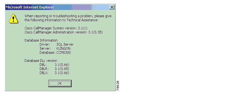
CallManager Software Release
The following figure shows the information about the release of CallManager being used.
CallManager Software Release
Lucent/Avaya Definity G3si Software Release
The following release of the Lucent/Avaya Definity G3si was used:
•
•
Cisco 2621 Router Configuration
The following shows the configuration of the Cisco 2621 router.
2621_B#show versionCisco Internetwork Operating System SoftwareIOS (tm) C2600 Software (C2600-JS-M), Version 12.2(3.5)T, MAINTENANCE INTERIM SOFTWARETAC Support: http://www.cisco.com/tacCopyright (c) 1986-2001 by cisco Systems, Inc.Compiled Fri 03-Aug-01 22:45 by ccaiImage text-base: 0x80008088, data-base: 0x81631DD8ROM: System Bootstrap, Version 12.1(3r)T2, RELEASE SOFTWARE (fc1)2621_B uptime is 4 minutesSystem returned to ROM by power-onSystem image file is "flash:c2600-js-mz.122-3.5.T"cisco 2621 (MPC860) processor (revision 0x200) with 56320K/9216K bytes of memory.Processor board ID JAD051516TX (503811939)M860 processor: part number 0, mask 49Channelized E1, Version 1.0.Bridging software.X.25 software, Version 3.0.0.SuperLAT software (copyright 1990 by Meridian Technology Corp).TN3270 Emulation software.Primary Rate ISDN software, Version 1.1.2 FastEthernet/IEEE 802.3 interface(s)31 Serial network interface(s)2 Channelized E1/PRI port(s)32K bytes of non-volatile configuration memory.16384K bytes of processor board System flash (Read/Write)Configuration register is 0x21022621_B#______________________________________________________________________________________2621_B#show diagSlot 0:C2621 2FE Mainboard Port adapter, 2 portsPort adapter is analyzedPort adapter insertion time unknownEEPROM contents at hardware discovery:Hardware Revision : 2.0PCB Serial Number : JAD051516TX (503811939)Part Number : 73-3200-08RMA History : 00RMA Number : 0-0-0-0Board Revision : A0Deviation Number : 0-21249EEPROM format version 4EEPROM contents (hex):0x00: 04 FF 40 00 A2 41 02 00 C1 17 4A 41 44 30 35 310x10: 35 31 36 54 58 20 28 35 30 33 38 31 31 39 33 390x20: 29 82 49 0C 80 08 04 00 81 00 00 00 00 42 41 300x30: 80 00 00 53 01 FF FF FF FF FF FF FF FF FF FF FF0x40: FF FF FF FF FF FF FF FF FF FF FF FF FF FF FF FF0x50: FF FF FF FF FF FF FF FF FF FF FF FF FF FF FF FF0x60: FF FF FF FF FF FF FF FF FF FF FF FF FF FF FF FF0x70: FF FF FF FF FF FF FF FF FF FF FF FF FF FF FF FFSlot 1:High Density Voice Port adapterPort adapter is analyzedPort adapter insertion time unknownEEPROM contents at hardware discovery:Hardware Revision : 1.1Top Assy. Part Number : 800-03567-01Board Revision : F1Deviation Number : 0-0Fab Version : 02PCB Serial Number : JAB05080LU9RMA Test History : 00RMA Number : 0-0-0-0RMA History : 00EEPROM format version 4EEPROM contents (hex):0x00: 04 FF 40 00 CC 41 01 01 C0 46 03 20 00 0D EF 010x10: 42 46 31 80 00 00 00 00 02 02 C1 8B 4A 41 42 300x20: 35 30 38 30 4C 55 39 03 00 81 00 00 00 00 04 000x30: FF FF FF FF FF FF FF FF FF FF FF FF FF FF FF FF0x40: FF FF FF FF FF FF FF FF FF FF FF FF FF FF FF FF0x50: FF FF FF FF FF FF FF FF FF FF FF FF FF FF FF FF0x60: FF FF FF FF FF FF FF FF FF FF FF FF FF FF FF FF0x70: FF FF FF FF FF FF FF FF FF FF FF FF FF FF FF FFVIC Slot 0:E1 (2 Port) Multi-Flex Trunk WAN Daughter CardHardware revision 1.0 Board revision B0Serial number 18801733 Part number 800-04479-01Test history 0x0 RMA number 00-00-00Connector type PCIEEPROM format version 1EEPROM contents (hex):0x20: 01 23 01 00 01 1E E4 45 50 11 7F 01 00 00 00 000x30: 58 00 00 00 00 03 09 00 FF FF FF FF FF FF FF FFHDV firmware: Compiled Fri 23-Mar-01 00:20 by miriyalaHDV memory size 524280 heap free 1750652621_B#______________________________________________________________________________________2621_B#show controllers e1 1/0E1 1/0 is up.Applique type is Channelized E1 - balancedNo alarms detected.alarm-trigger is not setVersion info Firmware: 20010710, FPGA: 15Framing is CRC4, Line Code is HDB3, Clock Source is Line.Data in current interval (62 seconds elapsed):0 Line Code Violations, 0 Path Code Violations0 Slip Secs, 0 Fr Loss Secs, 0 Line Err Secs, 0 Degraded Mins0 Errored Secs, 0 Bursty Err Secs, 0 Severely Err Secs, 0 Unavail Secs2621_B#____________________________________________________________________________________2621_B#show configurationUsing 1785 out of 29688 bytes!version 12.2no parser cacheservice timestamps debug datetime msec localtime show-timezoneservice timestamps log uptimeno service password-encryption!hostname 2621_B!no logging bufferedenable password cisco!!!memory-size iomem 15voice-card 1dspfarm!ip subnet-zero!!no ip domain-lookup!isdn switch-type primary-net5!!voice class codec 1codec preference 1 g729r8codec preference 2 g711ulawcodec preference 3 g711alaw!!!!!!!controller E1 1/0pri-group timeslots 1-31!controller E1 1/1shutdown!!!!interface FastEthernet0/0ip address 192.168.100.2 255.255.255.0no ip mroute-cacheload-interval 30no keepalivespeed autohalf-duplex!interface FastEthernet0/1ip address 10.1.1.129 255.255.255.0no ip mroute-cacheduplex autospeed auto!interface Serial1/0:15no ip addressno logging event link-statusisdn switch-type primary-net5isdn protocol-emulate networkisdn incoming-voice voiceisdn T321 40000isdn T203 30000isdn bchan-number-order ascendingno cdp enable!router ripnetwork 1.0.0.0network 192.168.100.0!ip classlessno ip http serverip pim bidir-enable!dialer-list 1 protocol ip permitdialer-list 1 protocol ipx permit!!snmp-server packetsize 4096snmp-server managertftp-server nvramcall rsvp-sync!voice-port 1/0:15!!mgcp profile default!dial-peer cor custom!!!dial-peer voice 1 potsdestination-pattern 2...direct-inward-dialport 1/0:15prefix 2!dial-peer voice 3 voipdestination-pattern 4...progress_ind setup enable 1voice-class codec 1session target ipv4:10.1.1.2dtmf-relay h245-alphanumeric!!line con 0exec-timeout 0 0line aux 0exec-timeout 0 0line vty 0 4exec-timeout 0 0password ciscologinline vty 5 15exec-timeout 0 0login!scheduler allocate 3996 1000!end2621_B#Test Configuration
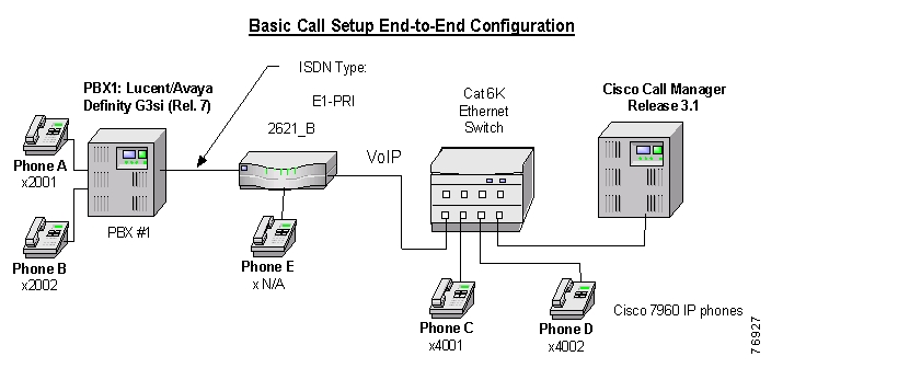
The following figure represents the various configurations used for testing.
Testbed Network Configuration
As shown in the figure above, a Lucent/Avaya Definity G3si PBX was connected via an ISDN E1 PRI link to a Cisco 2621 Gateway, which in turn, was connected to an Ethernet switch. The interoperability testing involved Layers 1, 2 and 3 on the ISDN PRI link between a Cisco 2621 and the PBX.
Layer 1 (Physical Layer)
The Lucent/Avaya Definity G3si PBX configuration screen for the E1 trunk interface is reached using the change ds1 a12 command, which sets the E1 physical layer parameters.
Layers 2 & 3 (Q.921 and Q.931)
Layer 2 and 3 packet exchanges were monitored using an Acacia Clarinet protocol analyzer, bridged across the PRI link in high impedance mode.
Layer 2 Q.921 packets were monitored to ensure that each PBX/2621 software configuration properly exchanged SABME/UA packets to initialize the ISDN link, and then RR packets were exchanged every 30 seconds.
Layer 3 Q.931 packets were monitored to ensure that the appropriate call setup/teardown packets were exchanged for each configuration, and that the SETUP packets contained the mandatory Information Elements with the necessary details, as well as optional IEs such as Calling Name and Number.
Telephone calls were made end-to-end in both directions through the Cisco 2621 Gateway, and a check was made to ensure that there was an audio path in both directions for each call.
User/Network Settings
The Cisco 2621 Gateway with ISDN protocol type setting of primary-net5 supports both protocol sides by using the isdn protocol-emulate network/user command.
The Lucent/Avaya Definity G3si PBX supports both "USER" and "NETWORK" protocol sides by using the change ds1 a12 command.
Test Results
Testing was performed by Test Engineer(s): Samir Batio, October 10, 2001
Test 1
In test 1:
•
•
The results are shown in the following tables.
Table 1 Basic Calls (Enbloc Sending)
Phone A to Phone C
Yes
Yes
Yes
No1
No1
Phone C to Phone A
Yes
Yes
Yes
Yes
No
1 CallManager is not sending the Connected Name or the Connected Number information in the connect message back to PBX.
Test 2
In test 2:
•
•
The test results are identical to those in Test 1.
![]()
![]()
![]()
![]()
![]()
![]()
![]()
![]()
Posted: Thu Sep 6 12:07:39 PDT 2007
All contents are Copyright © 1992--2007 Cisco Systems, Inc. All rights reserved.
Important Notices and Privacy Statement.