|
|

Table Of Contents
Configuring the Cisco ATA for SCCP
Specifying a Preconfigured VLAN ID or Disabling VLAN IP Encapsulation
Steps Needed to Configure the Cisco ATA
Basic Configuration Steps in a Cisco CallManager TFTP Server Environment
Basic Configuration Steps in a Non-TFTP Server Environment
Configuring the Cisco ATA Using a TFTP Server
Setting Up the TFTP Server with Cisco ATA Software
Configurable Features and Related Parameters
Creating a Cisco ATA Default Configuration File
Creating a Configuration File for a Specific Cisco ATA
Configuring the Cisco ATA to Obtain its Configuration File from the TFTP Server
Using the Voice Configuration Menu
Resetting the Cisco ATA to Factory Default Values
Cisco ATA Web Configuration Page
Resetting the Cisco ATA Using Cisco CallManager
Upgrading the SCCP Signaling Image
Configuring the Cisco ATA for SCCP
This section describes how to configure the Cisco ATA to operate with the Skinny Client Control Protocol (SCCP) signaling image and how the Cisco ATA obtains the latest signaling image.
You can configure the Cisco ATA for use with SCCP with any of the following methods:
•
By using the Cisco CallManager TFTP server—This is the Cisco-recommended method for deploying a large number of Cisco ATAs. This method allows you to set up a default configuration file for all Cisco ATAs in the network. Additionally, you can set up a configuration file that is unique to a specific Cisco ATA. When the Cisco ATA powers up or boots up from a reset, it automatically downloads its configuration file from the Cisco CallManager TFTP server and updates its configuration parameters.
•
–
–
This section contains the following topics:
•
•
•
•
•
•
•
•
Note
Default Boot Load Behavior
Before configuring the Cisco ATA, you need to know how the default Cisco ATA boot load process works. Once you understand this process, you will be able to configure the Cisco ATA by following the instructions provided in this section and in the sections that follow.
All Cisco ATAs are shipped with a boot load signaling-protocol image. However, because this image is not a fully functional Cisco ATA image, the Cisco ATA seeks to obtain the image-load information from the Cisco CallManager and perform a software upgrade. In addition, the Cisco ATA obtains the necessary SCCP-specific configuration files for Cisco CallManager communication and the Cisco ATA configuration file during the boot load process.
The following list summarizes the default Cisco ATA behavior during its boot-up process:
1.
Note
2.
Note
3.
4.
5.
Note
6.
7.
Note
Specifying a Preconfigured VLAN ID or Disabling VLAN IP Encapsulation
If you want the Cisco ATA to use a preconfigured VLAN ID instead of using the Cisco Discovery Protocol to locate a VLAN, or if you want to disable VLAN IP encapsulation, refer to Table 3-1 for a reference to the parameters and bits you may need to configure. Use the voice configuration menu to configure these parameters. (See the "Voice Configuration Menu" section for instructions on using this menu.) Also, refer to Table 3-2 for a matrix that indicates which VLAN-related parameters and bits to configure depending on your network environment.
Note
N/A indicates that the variable is not applicable to the feature and the setting of this variable does not affect the feature.
Example
The following procedure shows you how to configure the OpFlags and VLANSetting parameters to allow the Cisco ATA to use a user-specified VLAN ID. In this example, the voice VLAN ID is 115 (in decimal format).
Step 1
xxxx xxxx xxxx xxxx xxxx xxxx x101 xxxx
The remaining bits of the OpFlags parameter, using all default values, make up the following bitmap representation:
0000 0000 0000 0000 0000 0000 0xxx 0010
Therefore, the resulting value of the OpFlags parameter becomes the following bitmap representation:
0000 0000 0000 0000 0000 0000 0101 0010
In hexadecimal format, this value is 0x00000052.
Step 2
xx00 0001 1100 11xx xxxx xxxx xxxx xxxx
where 000001110011 is the binary representation of the decimal value 115.
The remaining bits of the VLANSetting parameter, using all default values, make up the following representation:
00xx xxxx xxxx xx00 0000 0000 0010 1011
Therefore, the resulting value of the VLANSetting parameter becomes the following bitmap representation:
0000 0001 1100 1100 0000 0000 0010 1011
In hexadecimal format, this value is 0x01cc002b.
Note
Steps Needed to Configure the Cisco ATA
This section contains the following topics:
•
•
Basic Configuration Steps in a Cisco CallManager TFTP Server Environment
Table 3-3 shows the basic steps for configuring the Cisco ATA and making it operational in a typical SCCP environment, which includes a Cisco CallManager TFTP server.
Table 3-3 Basic Steps to Configure the Cisco ATA in a Typical Cisco CallManager Environment
1.
2.
Note
3.
Configuring the Cisco ATA to Obtain its Configuration File from the TFTP Server
4.
5.
6.
7.
Basic Configuration Steps in a Non-TFTP Server Environment
Table 3-4 shows the basic steps for configuring the Cisco ATA without using the TFTP server method.
Table 3-4 Basic Steps to Configure the Cisco ATA Without Using the TFTP Server Method
1.
a.
b.
c.
Note
2.
3.
4.
5.
Configuring the Cisco ATA Using a TFTP Server
The TFTP method of configuration is useful when you have many Cisco ATA because you can use a TFTP server for remote, batch configuration of Cisco ATAs. A TFTP server can host one unique configuration file for each Cisco ATA.
This section contains the following topics:
•
•
•
•
•
Setting Up the TFTP Server with Cisco ATA Software
This section provides the procedure for the Cisco ATA administrator to obtain the correct Cisco ATA software and set up the Cisco CallManager TFTP server with this software.
Procedure
Step 1
Step 2
Note
Step 3
Step 4
Step 5
Step 6
Step 7
Step 8
Configurable Features and Related Parameters
Table 3-5 lists, in alphabetical order, various features that you can configure for the Cisco ATA. Table 3-5 also includes links to the related parameter that allows you to configure each of these features. Each link takes you to a detailed description of the parameter that includes its default values.
For an example of how to configure parameters for the TFTP Server configuration method, see the "Creating a Cisco ATA Default Configuration File" section.
Table 3-5 Configurable Features and Related Parameters
Audio Media Features
•
•
•
•
Audio Media Parameters
Caller ID format
Debug and Diagnostics
NPrintf, page 5-37, TraceFlags, page 5-38, SyslogIP, page 5-38, SyslogCtrl, page 5-39
Fax Services Features
•
•
Fax Services Parameters
•
Hook-flash detection timing configuration
Mid-call service format—Bellcore, Cisco VG248 or Cisco ATA
Network-related Features
•
•
•
•
•
•
Network-related Parameters
•
•
•
SCCP Terminal-related Features
•
•
•
•
•
SCCP Terminal-related Parameters
•
User Interface and TFTP Features
•
•
•
•
User Interface and TFTP Parameters
•
•
Packet Precedence Features
•
•
Packet Precedence Parameters
Polarity settings for FXS ports
Tone format: BusyTone, CallWaitTone
DialTone, DialTone2, ReorderTone, RingBackTone and AlertTone parametersTone parameters—Using Network Locale option versus using Cisco ATA tone parameters
ConnectMode, page 5-21—Bit 0
Version control of Cisco ATA configuration file
CFGID—Version Parameter for Cisco ATA Configuration File, page 5-40
Creating a Cisco ATA Default Configuration File
The Cisco ATA release-software zip files includes a file called atadefault.cfg, which is a binary file that contains all the default parameters for the Cisco ATA. However, you likely will need to create your own atadefault.cfg file to contain the default settings that you want Cisco ATAs in your environment to use. For information on each configuration parameter, including all default values, see Chapter 5, "Parameters and Defaults."
Use the text file called sk_example.txt as a basis for creating your default file. The sk_example.txt file is included in the software-release zip file and contains all default values. This file is shown without its annotations in the "Configuration Text File Template" section on page 5-2.
The following procedure illustrates how to create the Cisco ATA default configuration file, convert it to the required binary format that the Cisco ATA can read, and store it on the TFTP server so that the Cisco ATA will download it during the boot-up process:
Procedure
Step 1
Step 2
Step 3
Note
The syntax of the cfgfmt program follows:
Syntax
cfgfmt [Encryption options] -sccp -tptag.dat input-text-file output-binary-file
–
–
–
–
–
Example
cfgfmt -sccp -tptag.dat atadefault.txt atadefault
Step 4
During the boot-up process, the Cisco ATA will download the output file as its configuration file unless it first finds a Cisco ATA-specific configuration file named for the MAC address of the Cisco ATA. (If you want to create a MAC-address configuration file for a specific Cisco ATA, see the "Creating a Configuration File for a Specific Cisco ATA" section.)
Note
Creating a Configuration File for a Specific Cisco ATA
Once you have booted up the Cisco ATA, you may decide that you want to create a configuration file that is specific to one Cisco ATA.
The following procedure illustrates how to create a Cisco ATA-specific configuration file, convert it to the required binary format that the Cisco ATA can read, and store it on the TFTP server so that the Cisco ATA will download it as soon as you reset the Cisco ATA.
Procedure
Step 1
ata<macaddress>.txt
where macaddress is the non-dotted hexadecimal version of the MAC address of the Cisco ATA you are configuring. This non-dotted hexadecimal MAC address is labeled on the bottom of most Cisco ATAs next to the word "MAC." The file name must be exactly 15 characters long. (However, if this filename is supplied by the DHCP server, the name can be as long as 31 characters and can be any name with printable ASCII characters.)
If necessary, you can obtain the non-dotted hexadecimal MAC address by using the atapname.exe command. For information on using the atapname.exe command, see the "Using atapname.exe Tool to Obtain MAC Address" section. That section includes an example of a dotted decimal MAC address and its corresponding non-dotted hexadecimal address.
Note
Example
You might want to change the values of the following parameters, whose default values are shown first:
LBRCodec:3AudioMode:0x00350035You could change the values as follows:
LBRCodec:0AudioMode:0x00350034Step 2
Step 3
The syntax of the cfgfmt program follows:
Syntax
cfgfmt [Encryption options] -sccp -tptag.dat input-text-file output-binary-file
–
–
–
–
–
Example
cfgfmt -sccp -tptag.dat ata0a141e28323c.txt ata0a141e28323c
This example is based on a Cisco ATA MAC address of 10.20.30.40.50.60, which converts to the two-digit, lower-case hexadecimal representation of each integer as 0a141e28323c.
Step 4
Step 5
After being reset, the Cisco ATA will download this ata<macaddress> binary configuration file as its unique configuration file. This file takes precedence over the atadefault.cfg file. If the Cisco ATA finds an ata<macaddress> file on the TFTP server, the Cisco ATA does not look for the atadefault.cfg file.
Using atapname.exe Tool to Obtain MAC Address
This bundled tool is useful for converting the dotted decimal version of the Cisco ATA MAC address (available on the Cisco ATA Web configuration page or from the voice configuration menu code 24#) to its default Cisco ATA profile name. This name has the following format:
ataxxxxxxxxxxxx
where each xx is the two-digit, lower-case hexadecimal representation of each integer in the dotted, decimal version of the Cisco ATA MAC address. This is the name you use for the unique Cisco ATA binary configuration file.The following command and output show an example of this command.
Command Example
atapname.exe 10.20.30.40.50.60
Command Output
ata0a141e28323c
Note
Using Encryption With the cfgfmt Tool
The EncryptKey or EncryptKeyEx parameter can be used to encrypt binary files that are transferred over TFTP. You can change encryption keys for each Cisco ATA so that only one specific Cisco ATA can decode the information.
Cisco strongly recommends using the EncryptKeyEx parameter for encryption because this parameter provides a stronger encryption than the EncryptKey parameter that was used in Cisco ATA software releases prior to release 2.16.
You must use version 2.3 of the cfgfmt configuration-file generation tool to use the new EncryptKeyEx parameter. This tools comes bundled with Cisco ATA software version 3.0. To verify that you have version 2.3 of the cfgfmt tool type the following command:
cfgfmtThe version number of the cfgfmt tool will be returned.
You can configure the EncryptKeyEx parameter by using the Cisco ATA Web configuration page or by using the TFTP configuration method. (For more information, see the "EncryptKeyEx" section on page 5-7.)
You can configure the EncryptKey parameter by using the Cisco ATA Web configuration page, the voice configuration menu, or by using the TFTP configuration method. (For more information, see the "EncryptKey" section on page 5-6.)
By default, the Cisco ATA-specific ata<macaddress> configuration file(s) are not encrypted. If encryption is required, however, you must manually configure the EncryptKeyEx or EncryptKey parameter before you boot up the Cisco ATA so that the TFTP method is secure. The Cisco ATA uses the RC4 cipher algorithm for encryption.
Note
Note
This section contains the following topics:
•
•
Configuration Files that the cfgfmt Tool Creates
The number of output binary configuration files that the Cisco ATA produces is dependent on two factors:
•
•
Table 3-6 shows the names of the binary files that can be generated. One, two or four files can be generated.
Note
Note
Note
cfgfmt Tool Syntax and Examples
The syntax of the cfgfmt tool follows:
Syntax
cfgfmt [options] input outputSyntax Definitions—Options
•
•
•
•
•
•
•
•
•
•
Some parameters, specified in the ptag.dat file used by the cfgfmt tool, are marked as sensitive information (these parameters could include UIPassword, UID, PWD0). These parameters are not included in the output binary file if the -g switch is specified in the cfgfmt syntax.
Syntax Definitions—Required Parameters
•
•
Syntax examples
The cfgfmt.exe syntax affects how the EncryptKeyEx or EncryptKey parameters are used, as shown in the following examples. In these examples, input-text-file is the ata<macaddress>.txt file that you will convert to binary to create the ata<macaddress> configuration file(s) for the Cisco ATA; output-binary-file is that binary ata<macaddress> file, and Secret is the encryption key.
•
If input-text-file sets the Cisco ATA EncryptKey parameter to 0, then output-binary-file is not encrypted. If the input-text-file sets EncryptKey to a non-zero value, then output-binary-file is encrypted with that value.
•
This is an example of how you might perform encryption on a first-time Cisco ATA.
The -X (uppercase) option means that any value specified for the Cisco ATA EncryptKeyEx parameter in input-text-file is ignored. However, because Secret is not specified in this example, output-binary-file is not encrypted. Nevertheless, the EncryptKeyEx parameter and its value, if specified in input-file-text, will be included in output-binary-file for possible encryption at a later time. The next time the Cisco ATA fetches the configuration file from the TFTP server, the file will be encrypted with Secret.
•
This is an example of changing the encryption key from one key to another key.
The -X (uppercase) option means that any value specified for the Cisco ATA EncryptKeyEx parameter in input-text-file is ignored and the output-binary-file is encrypted with the Secret key. However, the EncryptKeyEx parameter and its value, if specified in input-text-file, will be included in output-binary-file.
Examples of Upgrading to Stronger Encryption Key
This section contains two examples of how you would upgrade your Cisco ATA configuration to use the stronger encyrption method if the current Cisco ATA firmware version was a version earlier than version 2.16.2. Versions earlier than 2.16.2 do not support the stronger EncryptKeyEx parameter.
Example 1
In this example, the Cisco ATA has not yet been deployed, but its firmware version is earlier than 2.16.2. Therefore, the Cisco ATA will upgrade to to firmware version 3.0 to use the EncryptKeyEx parameter as its encryption key.
The Cisco ATA in this example has a MAC address of 102030405060.
Perform the following steps:
Procedure
Step 1
Step 2
Step 3
EncryptKeyEx:231e2a7f10bd7fe/102030405060This means that only the Cisco ATA with the MAC address 102030405060 will be allowed to apply this EncryptKeyEx value to its internal configuration.
Step 4
Step 5
cfgfmt -g ata102030405060.txt ata102030405060This will generate the following two binary configuration files:
•
•
ata102030405060 is unencrypted.
ata102030405060.x is encrypted with EncryptKeyEx value.
Step 6
When the Cisco ATA powers up, it will obtain its IP address from the DHCP server. If the DHCP server specifies the TFTP server address, the Cisco ATA will contact the TFTP server obtained from DHCP because the Cisco ATA is not preconfigured with a TFTP server address. The boot process is as follows:
a.
b.
c.
d.
e.
f.
g.
h.
Note
Example 2
In this example, a new Cisco ATA has already been deployed (with the EncryptKey value set) with a firmware version earlier than 2.16.2. The Cisco ATA needs to be upgraded to version 2.16.2 firmware or greater to use EncryptKeyEx parameter to encrypt its configuration file.
In this scenario, you would follow the same procedure as in Example 1, except that you would need to set the EncryptKey value to the previously configured EncryptKey value. The difference is that the ata<macaddress> file is now encrypted with EncryptKey because the Cisco ATA expects the ata<macaddress> file to be encrypted with EncryptKey. The Cisco ATA can then begin using the ata<macaddress>.x file that is encrypted with the EncryptKeyEx parameter.
Configuring the Cisco ATA to Obtain its Configuration File from the TFTP Server
This section describes three methods from which to choose how the Cisco ATA contacts the TFTP server to obtain its configuration file:
–
–
Note
Using a DHCP Server
When using a DHCP server, configuration settings vary depending on whether or not the DHCP server is under the control of the Cisco ATA system administrator or the service provider. The simplest configuration is when the DHCP server is under the control of the Cisco ATA administrator, in which case the DHCP server provides the IP address of the TFTP server. Depending on who controls the DHCP server, follow the applicable configuration procedure:
•
•
This section also includes the topic:
•
Note
Procedure if DHCP Server is Under Control of Cisco ATA Administrator
Procedure
Step 1
•
•
•
If you use DHCP option 150, the Cisco ATA will ignore the DHCP siaddr field and DHCP option 66. If DHCP option 150 is not used, the Cisco ATA next looks for the DHCP field siaddr. If neither DHCP option 150 nor the siaddr field are available, the Cisco ATA looks for DHCP option 66. If you use DHCP option 66 or the DHCP siaddr field, you must turn off DHCP option 150 or set its value to 0.
Note
Step 2
•
•
•
•
•
This completes the parameter settings and DHCP options you need to configure for this procedure. The Cisco ATA will contact the DHCP server for the IP address of the TFTP server that contains the Cisco ATA configuration file.
Note
Procedure if DHCP Server is not Under Control of Cisco ATA Administrator
This is the procedure to use if the DHCP server is not under the control of the Cisco ATA administrator, which means that the URL of the TFTP server must be manually configured.
Procedure
Step 1
Note
Step 2
Step 3
Step 4
Step 5
This completes the parameter settings you need to configure for this procedure. The Cisco ATA will contact the manually configured TFTP server that contains the Cisco ATA configuration file.
Other DHCP Options You Can Set
The following parameters can also be configured with DHCP:
•
•
•
•
•
Note
Without Using a DHCP Server
Use the following procedure if you are not using a DHCP server in your environment but are still using a TFTP server to obtain the Cisco ATA configuration file:
Procedure
Step 1
Step 2
Step 3
Note
Step 4
Step 5
•
•
•
Other parameters that are normally supplied by DHCP may be provided statically by configuring their values. These parameters are:
•
•
•
This completes the parameter settings you need to configure in order for the Cisco ATA to contact the TFTP server (without using DHCP) that will contain the configuration file for the Cisco ATA.
Voice Configuration Menu
The main reasons to use the voice configuration menu are to establish IP connectivity for the Cisco ATA if a DHCP server is not being used in your network environment, and to reset the Cisco ATA to its factory values if necessary. You can also use the voice configuration menu if you need to configure a small number of parameters or if the web interface and TFTP configuration are not available.
Note
See Chapter 5, "Parameters and Defaults," for a complete list of parameters and their definitions. Also see Table 3-5 for an alphabetical listing of configurable features and references to their corresponding parameters.
This section contains the following topics:
•
•
•
Using the Voice Configuration Menu
To manually configure the Cisco ATA by using the voice configuration menu and the telephone keypad, perform the following steps:
Procedure
Step 1
Step 2
Step 3
Table 3-7 lists the menu options that you need to configure basic IP connectivity for the Cisco ATA, after which you can use the Cisco ATA web configuration page to configure additional parameters.
Note
Step 4
Note
Note
The voice configuration menu repeats the value you entered, then prompts you to press one of the following keys:
•
•
•
•
Step 5
Step 6
Step 7
Entering Alphanumeric Values
Some voice configuration menu options require you to enter alphanumeric characters. Alphanumeric entry differs from numeric entry because you must press # after each character selected.
If you need to enter an alphanumeric value, the voice prompt tells you to enter an alphanumeric value; otherwise, enter a numeric value (0 to 9).
Table 3-8 lists the keys on a telephone keypad and their respective alphanumeric characters.
Using Table 3-8 as a guide, enter the appropriate number key on the telephone keypad as many times as needed to select the number, letter, or symbol required. For example, to enter 58sQ, you would enter:
5 # 8 # 7 7 7 7 7 # 7 7 7 7 7 7 7 # #
Resetting the Cisco ATA to Factory Default Values
It is possible that you may, under some circumstances, want to reset the Cisco ATA to its factory default values. For example, this is the only way to recover a forgotten password without contacting your Cisco representative.
To perform a factory reset, you must use the voice configuration menu and follow these steps:
Procedure
Step 1
Step 2
Step 3
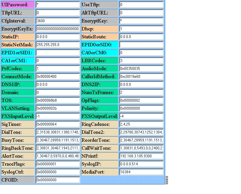
Cisco ATA Web Configuration Page
You can use the Cisco ATA web configuration page in a non-TFTP configuration environment, or in a TFTP configuration environment as a read-only record of individual customer parameters.
Figure 3-1 shows an example of the Cisco ATA web configuration page, which displays all configurable parameters.
Note
Figure 3-1 Cisco ATA Web Configuration Page
You can access the web configuration page from any graphics-capable browser, such as Microsoft Internet Explorer or Netscape. This provides easy initial access to the Cisco ATA configuration within the administrator's private network.
Follow these steps to set parameters using the web configuration page:
Procedure
Step 1
Step 2
Step 3
http://IP Address/devFor example, the configuration page for a Cisco ATA with the IP address 192.168.3.225 is:
http://192.168.3.225/devStep 4
Note
Step 5
The Cisco ATA automatically refreshes its configuration.
Step 6
Resetting the Cisco ATA Using Cisco CallManager
Whenever you make configuration changes to the Cisco ATA, you must reset the Cisco ATA using the Cisco CallManager for these configuration changes to take effect. To reset the Cisco ATA, use the following procedure:
Procedure
Step 1
Step 2
Step 3
Step 4
Step 5
Step 6
Step 7
Step 8
Upgrading the SCCP Signaling Image
For instructions on how to upgrade the Cisco ATA to the most recent SCCP signaling image, refer to the following list:
•
•
![]()
![]()
![]()
![]()
![]()
![]()
![]()
![]()
Posted: Thu Apr 1 11:46:44 PST 2004
All contents are Copyright © 1992--2004 Cisco Systems, Inc. All rights reserved.
Important Notices and Privacy Statement.