cc/td/doc/product/voice/ata/ataadmn
hometocprevnextglossaryfeedbacksearchhelp
PDF

Table Of Contents

Cisco Analog Telephone Adaptor Overview

Overview of the Skinny Client Control Protocol

Hardware Overview

Software Features

SCCP Version

Voice Codecs Supported

Additional Supported Signaling Protocols

Other Supported Protocols

Basic Services

Fax Services

Pre-call and Mid-call Services

Installation and Configuration Overview

Cisco Analog Telephone Adaptor Overview


This section describes the hardware and software features of the Cisco Analog Telephone Adaptor (Cisco ATA) and includes a brief overview of the Skinny Client Control Protocol (SCCP).

The Cisco ATA analog telephone adaptors are handset-to-Ethernet adaptors that allow regular analog telephones to operate on IP-based telephony networks. Cisco ATAs support two voice ports, each with an independent telephone number. The Cisco ATA 188 also has an RJ-45 10/100BASE-T data port.

This section covers the following topics:

Overview of the Skinny Client Control Protocol

Hardware Overview

Software Features

Installation and Configuration Overview

Figure 1-1 Cisco ATA Analog Telephone Adaptor

The Cisco ATA, which operates with Cisco voice-packet gateways, uses broadband pipes deployed through digital subscriber line (DSL), fixed wireless, cable modem, and other Ethernet connections.


Note The term Cisco ATA refers to both the Cisco ATA 186 and the Cisco ATA 188, unless otherwise stated.


Note This guide provides information about the SCCP image for the Cisco ATA. The features and functionality described in this guide do not necessarily pertain to the features and functionality provided by the other protocol loads available for the Cisco ATA. Each protocol load has its own administrator's guide. If you are looking for information about the behavior of the Cisco ATA for a protocol other than SCCP, please refer to the administrator's guide specific to that protocol.


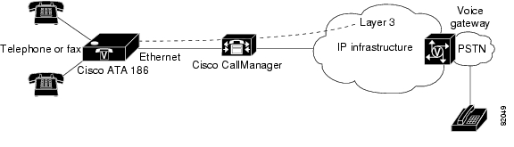
Figure 1-2 The Cisco ATA 186 as an Endpoint in an SCCP Network

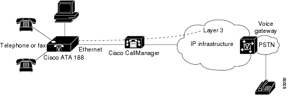
Figure 1-3 The Cisco ATA 188 as an Endpoint in an SCCP Network

Overview of the Skinny Client Control Protocol

The Skinny Client Control Protocol (SCCP) is the Cisco standard for real-time calls and conferencing over Internet Protocol (IP). With SCCP, Cisco IP Phones can co-exist in an H.323 environment. When a Cisco CallManager is coupled with an H.323 Gatekeeper or an MGCP Call Agent, a Cisco ATA running SCCP interoperates with H.323 terminals on the far end to establish, control and clear audio calls.

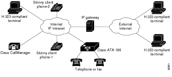
Figure 1-4 illustrates the architecture of an SCCP network.

Figure 1-4 SCCP Architecture

Hardware Overview

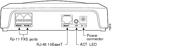
Cisco ATAs are compact, easy-to-install devices. Figure 1-5 shows the rear panel of the Cisco ATA 186. Figure 1-6 shows the rear panel of the Cisco ATA 188.

Figure 1-5 Cisco ATA 186—Rear View

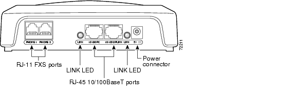
Figure 1-6 Cisco ATA 188—Rear View

The unit provides the following connectors and indicators:

5V power connector.

Two RJ-11 FXS (Foreign Exchange Station) ports—The Cisco ATA supports two independent RJ-11 telephone ports that can connect to any standard analog telephone device. Each port supports either voice calls or fax sessions, and both ports can be used simultaneously.


Note The Cisco ATA186-I1 and Cisco ATA188-I1 provide 600-ohm resistive impedance. The Cisco ATA186-I2 and Cisco ATA188-I2 provide 270 ohm + 750 ohm // 150-nF complex impedance. The impedance option is requested when you place your order and should match your specific application. If you are not sure of the applicable configuration, check your country or regional telephone impedance requirements.


Ethernet ports

The Cisco ATA 186 has one RJ-45 10BASE-T uplink Ethernet port to connect the Cisco ATA 186 to a 10/100BASE-T hub or another Ethernet device.

The Cisco ATA 188 has two Ethernet ports: an RJ-45 10/100BASE-T uplink port to connect the Cisco ATA 188 to a 10/100BASE-T hub or another Ethernet device and an RJ-45 10/100BASE-T data port to connect an Ethernet-capable device, such as a computer, to the network.


Note The Cisco ATA 188 performs auto-negotiation for duplexity and speed and is capable of 10/100 Mbps, full-duplex operation. The Cisco ATA 186 is fixed at 10 Mbps, half-duplex operation.


The Cisco ATA 188 RJ-45 LED shows network link and activity. The LED blinks twice when the Cisco ATA is first powered on, then turns off if there is no link or activity. The LED blinks to show network activity and is solid when there is a link.

The Cisco ATA 186 RJ-45 LED is solid when the Cisco ATA is powered on and blinks to show network activity.

Function button—The function button is located on the top panel of the unit (see Figure 1-7).

Figure 1-7 Function Button

The function button lights when you pick up the handset of a telephone attached to the Cisco ATA. The button blinks quickly when the Cisco ATA is upgrading its configuration.


Note If the function button blinks slowly, the Cisco ATA cannot find the DHCP server. Check your Ethernet connections and make sure the DHCP server is available.


Pressing the function button allows you to access to the voice configuration menu. For additional information about the voice configuration menu, see the "Voice Configuration Menu" section on page 3-22.


Caution Never press the function button during an upgrade process. Doing so may interfere with the process.

Software Features

This section contains topics that cover the protocols and services that the Cisco ATA supports:

SCCP Version

Voice Codecs Supported

Additional Supported Signaling Protocols

Other Supported Protocols

Basic Services

Fax Services

Pre-call and Mid-call Services

SCCP Version

The Cisco ATA supports the Skinny Client Control Protocol (SCCP) Rev. 3.0 and 3.1.

Voice Codecs Supported

The Cisco ATA supports the following voice codecs (check your other network devices for the codecs they support):

G.711µ-law

G.711A-law

G.723.1

G.729

G.729A

G.729B

G.729AB

When operating with a low-bit-rate codec, the Cisco ATA can support either two G.723.1 connections or one G.729 connection. The selection of G.723.1 or G.729 must be statically configured. When G.723.1 is the low-bit-rate codec, each FXS port is allocated with one G.723.1 connection. When G.729 is used, only one FXS port can use G.729. For more information, see the "LBRCodec" section on page 5-13 and "ConnectMode" section on page 5-21.

Additional Supported Signaling Protocols

In addition to SCCP, the Cisco ATA supports the following signaling protocols:

Media Gateway Control Protocol (MGCP)

H.323

Session Initiation Protocol (SIP)

If you wish to perform a cross-protocol upgrade from SCCP to another signaling image, see "Performing a Cross-Protocol Upgrade."

Other Supported Protocols

Other protocols that the Cisco ATA supports include the following:

802.1Q VLAN tagging

Cisco Discovery Protocol (CDP)

Domain Name System (DNS)

Dynamic Host Configuration Protocol (DHCP)

Internet Control Message Protocol (ICMP)

Internet Protocol (IP)

Real-Time Transport Protocol (RTP)

Transmission Control Protocol (TCP)

Trivial File Transfer Protocol (TFTP)

User Datagram Protocol (UDP)

Basic Services

For an alphabetical list of Cisco ATA basic services and the parameters for configuring each service, see Table 3-5 on page 3-8.

These services include the following features:

Configurable tone (dial tone, busy tone, confirm tone, reorder tone, call waiting tone)

IP address assignment—DHCP-provided or statically configured

Cisco ATA configuration by means of the Cisco CallManager TFTP server, web browser, or voice configuration menu.

VLAN configuration

Caller ID format

Ring cadence format

Distinctive ring (external calls have two rings with a short pause between rings)

Silence suppression

Low-bit-rate codec selection

RTP media port configuration

Hook-flash detection timing configuration

Cisco Discovery Protocol (CDP)

User interface password

Type of Service (ToS) configuration for audio and signaling ethernet packets

802.1P Class of Service (Cos) Bit configuration

Debugging and diagnostic tools

Fax Services

The Cisco ATA supports two modes of fax services, in which fax signals are transmitted using the G.711 codec:

Fax pass-through mode—Receiver-side Called Station Identification (CED) tone detection with automatic G.711A-law or G.711µ-law switching.

Fax mode—The Cisco ATA is configured as a G.711-only device.

How you set Cisco ATA fax parameters depends on what network gateways are being used. You may need to modify the default fax parameter values (see Chapter 6, "Configuring and Debugging Fax Services").


Note Success of fax transmission depends on network conditions and fax modem response to these conditions. The network must have reasonably low network jitter, network delay, and packet loss rate.


Pre-call and Mid-call Services

This section provides an overview of telephone services that the Cisco ATA allows the user to perform either before or during a call. For end-user procedures on how to use these services, see "How to Use Pre-call and Mid-call Services."

This section contains the following topics:

Pre-call Services

Mid-call Services


Note The services listed in this section are supported by Cisco CallManager. For Cisco IOS Telephony Service (ITS)-supported services, refer to ITS documentation.


Pre-call Services

Table 1-1 lists the pre-call services that the Cisco ATA supports for the SCCP protocol. Table 1-1 also includes references to where the user procedure is described for each service.

Table 1-1 Pre-call Services and Where to Find End-user Procedures

Service
Procedure Reference

Voice mail access

Access Voicemail

Change access code

Change Your Pre-Call Service Access Code

Forward all calls to another number

Activate Call-Forward-All

Cancel the forwarding of all calls

Cancel Call-Forward-All

Redial the most recent number dialed

Redial

Use speed dial

Speed Dial

Answer a call in your call-pickup group

Call Pickup

Answer a call outside of your call-pickup group

Group Call Pickup

Set up a conference

MeetMe Conference


Mid-call Services

The method of initiating and using mid-call services for the SCCP protocol differs according to mode. The following three modes are available for invoking mid-call services:

Bellcore Style (default)

Cisco VG248 Style

Cisco ATA Style

The mode can be configured using bits 28 and 29 of the ConnectMode parameter (see the "ConnectMode" section on page 5-21).

Table 1-2 lists the mid-call services that the Cisco ATA supports for each of the three modes. Table 1-2 also includes references to where the end-user procedure is described for each service.

Table 1-2 Mid-call Services and Where to Find End-user Procedures

Style and Related Services
Procedure Reference

Bellcore style (default) services:

Call transfer

Conference call

Bellcore Style

Cisco VG248 style services:

Three-way call

Call transfer

Conference call

Cisco VG248 Style

Cisco ATA style services:

Call hold/resume

Call transfer

Conference call

Cisco ATA Style


Installation and Configuration Overview

Table 1-3 provides the basic steps required to install and configure the Cisco ATA to make it operational in a typical Cisco CallManager environment.

Table 1-3 Overview of the Steps Required to Install and Configure the Cisco ATA and Make it Operational

Action
Reference

1. Plan the network and Cisco ATA configuration.


2. Install the Ethernet connection.


3. Install and configure the other network devices.


4. Install the Cisco ATA but do not power up the Cisco ATA yet.

Note If you power up the Cisco ATA before adding the Cisco ATA to the Cisco CallManager, you will need to perform a reset once you have added the Cisco ATA to the Cisco CallManager.

What the Cisco ATA Package Includes


Resetting the Cisco ATA Using Cisco CallManager, page 3-26

5. Download the desired Cisco ATA release software zip file from the Cisco web site, then configure the Cisco ATA.

Chapter 3, "Configuring the Cisco ATA for SCCP"

6. Add the Cisco ATA to the Cisco CallManager.

"Adding the Cisco ATA to the Cisco CallManager"

7. Power up the Cisco ATA.


8. Periodically, you can upgrade an individual Cisco ATA or all Cisco ATAs to a new signaling image by using the Cisco CallManager administration web pages.

Chapter 7, "Upgrading the Cisco ATA Signaling Image"


hometocprevnextglossaryfeedbacksearchhelp

Posted: Thu Apr 1 11:46:52 PST 2004
All contents are Copyright © 1992--2004 Cisco Systems, Inc. All rights reserved.
Important Notices and Privacy Statement.