|
|

The Interface Controller Card (ICC) Universal Protocol Generator (UPG) Update Tool is available for users of VCO/4K system software version 5.1(3) and higher. The tool allows users to modify the default .upg files in order to create custom ICC protocol data files for E&M and CAS/R2 protocols. Two versions of the ICC UPG Update Tool are provided on a floppy disk, shown in Figure D-1.

Two versions of the default files are provided on a disk:
 |
Note Default files do not need to be customized for the system software to function properly. The ability to customize the default .upg files is provided for flexibility in signaling configurations. |
Users must modify a system default .upg file to create a custom .upg file. Customize the iccem.upg file when using the E&M, T1 protocol. Customize the icccasr2.upg file when using the CAS/R2, E1 protocol. A maximum of four customized .upg files may be created; the ability to customize .upg files is provided for configuring flexibility in three signaling areas:
The ICC UPG Update Tool is a command line executable software program. The following sections describe the installation of the ICC UPG Update Tool and the creation of customized .upg files using either a Sun Solaris workstation or a PC workstation.
Complete the following steps to install the ICC UPG Update Tool on a SUN Solaris workstation and create a customized .upg data file. For Microsoft Windows PC users, refer to the "Install and Start the ICC UPG Update Tool with a Microsoft Windows PC Workstation" section for tool installation instructions.
Step 1 Create a directory named UPGTOOL on your Sun workstation.
Step 2 Copy the upgedsol.exe executable file—the ICC UPG Update Tool—from the ICC PROTOCOL GENERATOR floppy disk to the UPGTOOL directory.
Step 3 Copy the appropriate default .upg file from floppy disk 6 to the UPGTOOL directory according to the following rules:
Step 4 Start a new shell.
Step 5 Change to the UPGTOOL directory within the new shell.
Step 6 Type ./upgedsol.exe and press Enter to start the tool.
An introductory message and prompt are displayed. (See Figure D-2.)
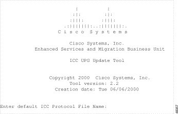
Step 7 Enter the file name of the default .upg file copied in Step 3.
The ICC UPG Update Tool menu, and a prompt, are displayed. (See Figure D-3.)
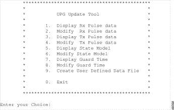
The ICC UPG Update Tool menu options, and custom .upg file creation instructions, are described in the "Custom .upg File Creation Instructions" section.
Complete the following steps to install and start the ICC UPG Update Tool on a Microsoft Windows PC workstation. For Sun Solaris users, refer to the "Install and Start the ICC UPG Update Tool with a Sun Solaris Workstation" section for tool installation instructions.
Step 1 Create a directory named UPGTOOL on your PC.
Step 2 Copy the upgedwin.exe executable file—the ICC UPG Update Tool—from the ICC PROTOCOL GENERATOR floppy disk to the UPGTOOL directory.
Step 3 Copy the appropriate default .upg file from floppy disk 6 to the UPGTOOL directory according to the following rules:
Step 4 Open a Command Prompt window.
Step 5 Change to the UPGTOOL directory within the window.
Step 6 Type upgedwin.exe and press Enter to start the tool.
An introductory message and prompt are displayed in the window. (See Figure D-4.)
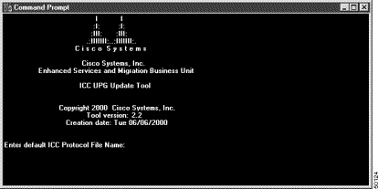
Step 7 Enter the file name of the default .upg file copied in Step 3.
The ICC UPG Update Tool menu, and a prompt, are displayed. (See Figure D-5.)

Refer to the "Custom .upg File Creation Instructions" section for a description of the ICC UPG Update Tool menu options, and custom .upg file creation instructions.
The creation of custom .upg files is accomplished with the ICC UPG Update Tool. All customizing instructions are illustrated with figures representative of those seen while using a Sun Solaris workstation. PC workstation users see the same information, but in a Command Prompt window.
Sun Solaris workstations users, refer to Figure D-3 for the ICC UPG Update Tool menu. PC workstation users, refer to Figure D-5 for the ICC UPG Update Tool menu. The ICC UPG Tool menu options are described in Table D-1.
Follow the procedures in the following sections to customize a default .upg file.
Complete the following steps to display and modify the receive pulse data of a default .upg file:
Step 1 From the ICC UPG Update Tool menu, type 1 and press Enter.
The receive pulse data is displayed on your screen (see Figure D-6), followed by the ICC UPG Update Tool menu and the Enter your Choice prompt.

Each protocol can detect a certain number of receive pulses (our example, Figure D-6, contains four). Each pulse is described by four parameters. (See Table D-2.)
| Parameter | Description |
|---|---|
Name | Name for the pulse; for debugging and maintenance only. |
ABCD bits | The ABCD bit pattern identifying a specific signal. The pattern is a binary number from 0000 to 1111, which is displayed as decimal, 0 to 15. |
Timing (ms), Min | Represents the minimum time, in milliseconds, that the active bit pattern (see Table D-3) must be present on the incoming line. |
Timing (ms), Max | Represents the maximum time, in milliseconds, that the active bit pattern (see Table D-3) can be present on the incoming line. |
Step 2 Type 2 and press Enter to modify the receive pulse data.
The first receive pulse data is displayed. (See Figure D-7.) The cursor is located after the Enter ABCD Bits value (0-15) [ n] prompt. The default, or current, value is contained within the square brackets.

Step 3 Modify the ABCD bit pattern, taking into account the following considerations:
 |
Note Only the active bit pattern is stored in the customized .upg file. |
| Signaling Name | Start Pattern | Active Pattern | End Pattern |
|---|---|---|---|
Seize | 0000 | 1100 | — |
Wink | 0000 | 1100 | 0000 |
Flash | 1100 | 0000 | 1100 |
Idle | 1100 | 0000 | — |
| Signaling Name | Bit Pattern |
|---|---|
Seize | 0001 |
Seize Acknowledge | 1101 |
Answer | 0101 |
Clear Back | 1101 |
Idle | 1001 |
a. Convert the appropriate binary ABCD bit pattern to decimal.
b. Type the decimal value.
c. Press Enter.
 |
Note Pressing Enter without first entering a value leaves the default, or current, value unmodified. |
A new prompt—Enter Minimum Timer Value (ms) [ n]—followed by the cursor, is displayed. (See Figure D-8.) The default, or current, value is contained within the square brackets.

Step 4 Modify the minimum timer value, taking into account the following considerations:
| Signaling Name | Minimum Time (ms) |
|---|---|
Seize | 375 |
Wink | 100 |
Flash | 100 |
Idle | 375 |
d. Type the appropriate minimum timer value for the seize receive pulse.
e. Press Enter.
 |
Note Pressing Enter without first entering a value leaves the default, or current, value unmodified. |
A new prompt—Enter Maximum Timer Value (ms) [ n]—followed by the cursor, is displayed. (See Figure D-9.) The default, or current, value is contained within the square brackets.

Step 5 Modify the maximum timer value, taking into account the following considerations:
| Signaling Name | Maximum Time (ms) |
|---|---|
Seize | 0 |
Wink | 350 |
Flash | 350 |
Idle | 0 |
 |
Note A zero maximum timer value indicates that the pattern can remain indefinitely. |
a. Type the appropriate maximum timer value for the seize receive pulse.
b. Press Enter.
 |
Note Pressing Enter without first entering a value leaves the default, or current, value unmodified. |
The second receive pulse data is displayed, along with the Enter ABCD Bits value (0-15) [ n] prompt.
Step 6 Repeat Step 3 through Step 5 for this and all remaining receive pulse data.
When all receive pulse data are modified, the ICC UPG Update Tool screen is displayed. Sun Solaris workstation users, refer to Figure D-3. Microsoft Windows PC workstations users, refer to Figure D-5.
Complete the following steps to display and modify the transmit pulse data of a default .upg file:
Step 1 From the ICC UPG Update Tool menu, type 3 and press Enter.
The transmit pulse data is displayed (see Figure D-10), followed by the ICC UPG Update Tool menu and the Enter your Choice prompt.
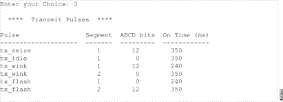
Each protocol can send a certain number of transmit pulses (our example, Figure D-10, contains four). Each pulse is described by four parameters. (See Table D-7.)
 |
Note The transmit pulses wink and flash are assigned two segments. Each segment contains an ABCD bit pattern value and an active bit pattern timing value. Both can be modified. |
| Parameter | Description |
|---|---|
Pulse | Name of the pulse. |
Segment | A numerical identifier for each segment of a pulse; a pulse is assigned one or two segments. |
ABCD bits | The ABCD bit pattern that is to be transmitted. The pattern is a binary number from 0000 to 1111, which is displayed as decimal, 0 to 15. |
On Time (ms) | Represents the guaranteed time, in milliseconds, that the active bit pattern (refer to Table D.8) will be transmitted on the outgoing line. |
Step 2 Type 4 and press Enter to modify the transmit pulse data.
The first transmit Pulse ID data is displayed (seize). (See Figure D-11.) The cursor is located after the Enter ABCD Bits value (0-15) [ n] prompt. The default, or current, value is contained within the square brackets.

Step 3 Modify the ABCD bit pattern, taking into account the following considerations:
| Signaling Name | Start Pattern | Active Pattern | End Pattern |
|---|---|---|---|
Seize | 0000 | 1100 | — |
Wink | 0000 | 1100 | 0000 |
Flash | 1100 | 0000 | 1100 |
Idle | 1100 | 0000 | — |
| Signaling Name | Bit Pattern |
|---|---|
Seize | 0001 |
Seize Acknowledge | 1101 |
Answer | 0101 |
Clear Back | 1101 |
Idle | 1001 |
a. Convert the appropriate binary ABCD bit pattern to decimal.
b. Type the decimal value.
c. Press Enter.
 |
Note Pressing Enter without first entering a value leaves the default, or current, value unmodified. |
A new prompt—Enter Time On Value (ms) [ n]—followed by the cursor, is displayed. (See Figure D-12.)

Step 4 Modify the minimum timer value (segment 1 timer value), taking into account the following considerations:
| Signaling Name | Minimum Time (ms) |
|---|---|
Seize | 375 |
Wink | 100 |
Flash | 100 |
Idle | 375 |
a. Type the appropriate minimum timer value for the seize receive pulse.
b. Press Enter.
 |
Note Pressing Enter without first entering a value leaves the default, or current, value unmodified. |
Step 5 Use the following considerations to determine your next step.
Step 6 Modify the ABCD end bit pattern (segment 2) following the guidelines discussed in Step 3.
Step 7 Modify the maximum timer value (segment 2 timer value), taking into account the following considerations.
 |
Note Transmit pulses wink and flash are the only transmit pulses with maximum timer values. The maximum timer values are always contained in segment 2 of a transmit pulse. |
| Signaling Name | Maximum Time (ms) |
|---|---|
Seize | 0 |
Wink | 350 |
Flash | 350 |
Idle | 0 |
 |
Note A zero maximum timer value indicates that the pattern can remain indefinitely. |
a. Type the appropriate maximum timer value for the transmit pulse.
b. Press Enter.
 |
Note Pressing Enter without first entering a value leaves the default, or current, value unmodified. |
The next transmit pulse data is displayed, along with the Enter ABCD Bits value (0-15) [ n] prompt.
Step 8 Repeat Step 3 through Step 5 for this and all remaining transmit pulse data.
When all transmit pulse data is modified, the ICC UPG Update Tool screen is displayed. SUN Solaris workstation users, refer to Figure D-3. Microsoft Windows PC workstation users, refer to Figure D-5.
 |
Note It is not necessary to access option 5 or option 6 to create a customized .upg file. Option 5 is display only, and option 6 is not available for customer use at this time. We advise proceeding to the "Display and Modify the Guard TimeOptions 7 and 8" section. |
Complete the following steps to display the state model:
Step 1 From the ICC UPG Update Tool screen, type 5 and press Enter, to display the current state model. The current state model, which describes protocol states, is displayed. (See Figure D-13.)
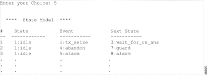
The state model is described by four parameters. (See Table D-12.)
| Parameter | Description |
|---|---|
# | A sequential number list which gives the state model display structure. |
State | The current state of the protocol.1 |
Event | Transition identifier; event possibly encountered.1 |
Next State | Resulting state; the state achieved if State and Event conditions are met.1 |
| 1The last three parameters described in Table D-12 require some explanation. Using the #2 row of Figure D-13 as an example, if the current protocol state is idle (1:idle) and the abandon event is encountered, the next state which the protocol assumes is guard (7:guard). |
The state model display is followed by the ICC UPG Update Tool menu.
Step 2 Proceed to the "Display and Modify the Guard TimeOptions 7 and 8" section. Do not select option 6.
 |
Note Option 6 is not supported for customer use at this time. However, if you happen to select option 6, press Enter to accept default values until the ICC UPG Update Tool menu is displayed. |
Complete the following steps to display and modify the guard time of a default .upg file:
Step 1 Type 7 and press Enter, to display the guard time.
The message in Figure D-14 is displayed, followed by the ICC UPG Update Tool menu and the Enter your Choice prompt.

A port is held in the guard state, after it is abandoned (the call associated with that port has ended), for the length of time specified by the guard time.
Step 2 Type 8 and press Enter to modify the guard time.
The message in Figure D-15 is displayed. The cursor is located after the Enter new Guard Time in milliseconds [ n] prompt. The default, or current, value is contained within the square brackets.

Step 3 Type an appropriate guard time value and press Enter.
 |
Note Pressing Enter without first entering a value leaves the default, or current, value unmodified. |
The ICC UPG Update Tool menu is displayed. Sun Solaris workstation users, refer to Figure D-3. Microsoft Windows PC workstation users, refer to Figure D-5.
Complete the following steps to save the customized receive and transmit pulse modifications to a new .upg file:
Step 1 From the ICC UPG Update Tool screen, type 7 and press Enter.
The message in Figure D-16 is displayed. The cursor is located after the Enter (3-6) prompt.

Step 2 Type a number from 3 to 6.
Step 3 Press Enter.
The information in Figure D-17 is displayed.

The number entered in Step 2 is used to create three items:
Table D-13 describes the items created with Step 2 for the E&M, T1 protocol.
| Step 2 Number Entry | File Name | Protocol ID | Signaling Type |
|---|---|---|---|
3 | icc03.upg | USER03 | E&M031 |
4 | icc04.upg | USER04 | E&M041 |
5 | icc05.upg | USER05 | E&M051 |
6 | icc06.upg | USER06 | E&M061 |
| 1T1 signaling types are displayed as selectable SIG. TYPE field values within the VCO/4K software administration's ICC Programmable Trunk Configuration screen. |
Table D-14 describes the items created with Step 2 for the CAS/R2, E1 protocol.
| Step 2 Number Entry | File Name | Protocol ID | Span Type |
|---|---|---|---|
3 | icc03.upg | USER03 | Cas031 |
4 | icc04.upg | USER04 | Cas041 |
5 | icc05.upg | USER05 | Cas051 |
6 | icc06.upg | USER06 | Cas061 |
| 1E1 signaling types are displayed as selectable SPAN TYPE field values within the VCO/4K software administration's ICC Programmable Trunk Configuration screen. |
 |
Note Switch configuration with the customized .upg file makes use of the different files and names created in Step 2; keep accurate records. |
Step 4 Press Enter to return to the ICC UPG Update Tool screen.
From the ICC UPG Update Tool screen, type 0 and press Enter to exit from the tool.
Copy the customized .upg file from the hard drive to a floppy disk.
A new custom .upg file is now ready for implementation on the VCO/4K switch. Refer to the "Switch Configuration with a Customized .upg File" section for complete configuration instructions.
Complete the following steps to configure the VCO/4K switch with a customized .upg file.
Step 1 Access the VCO/4K software administration's Copy Files screen.
Step 2 Copy the customized .upg file from the floppy disk (the file created on the floppy disk with instructions in the "Custom .upg File Creation Instructions" section) to the C:/BOOT directory on both the A and B sides of the switch.
Step 3 Access the VCO/4K software administration Card Maintenance screen.
Step 4 Take the entire ICC out of service (OOS).
Step 5 Access the Card Summary screen via the Database Administration menu.
Step 6 Display the span of the ICC you want to configure with the customized .upg file.
The ICC Programmable Trunk Configuration screen is displayed.
Step 7 Use the SIG. TYPE field (for the E&M, T1 protocol) to select the customized .upg file signaling type for each port for which it is appropriate. Use the SPAN TYPE field (for the CAS/R2, E1 protocol) to select the customized .upg file signaling type for each port for which it is appropriate.
 |
Note The customized SIG. TYPE (T1) or SPAN TYPE (E1) field selections are those created in
the "Save a Customized .upg Data
FileOption 9" section, and described in
Table D-13 and
Table D-14. When you select or modify the signaling type on port 1, the "Enter Y to propagate port 1 values" message is displayed. Enter Y to configure all remaining ports with the same signaling type as that of port 1. Enter N to configure only port 1 with a particular signaling type. |
Step 8 Access the VCO/4K software administration Card Maintenance screen.
Step 9 Activate the ICC.
The customized .upg file is now configured in the switch and the new protocol is implemented.
Keep the following restrictions and limitations in mind when configuring the switch with customized .upg files.
 |
Caution The ICC UPG Update Tool allows you to create customized .upg files that may not be valid for the VCO/4K system. Interruption of service and loss of calls may occur. |
![]()
![]()
![]()
![]()
![]()
![]()
![]()
![]()
Posted: Sat Sep 28 15:07:43 PDT 2002
All contents are Copyright © 1992--2002 Cisco Systems, Inc. All rights reserved.
Important Notices and Privacy Statement.