|
|

The following sections describe IPRC installation procedures for the Cisco VCO/4K, as well as installation procedures for legacy Summa Four VCO and SDS systems.
To install an IPRC in a VCO/20 or VCO/4K system, perform the following steps:
Step 1 Turn off the power to the VCO/4K at the main breaker.
Step 2 Install the IPRCs in the front of the VCO/4K chassis according to the generic installation procedures in the Cisco VCO/4K Card Technical Descriptions.
Step 3 Loosen the top and bottom screws on both rear-mounted Storage/Control I/O Modules and remove the modules from the rear of the system. Figure 2-1 shows the location of the Storage/Control I/O Modules. For more information about removing the Storage/Control I/O Modules, refer to the Cisco VCO/4K Mechanical Assemblies.
 |
Tip While removing the Storage/Control I/O Modules, use a gentle up-and-down rocking motion to help remove the modules with minimum force. |
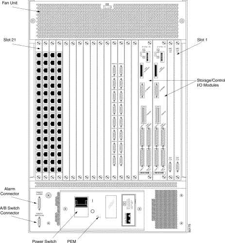
Step 4 Connect the smaller terminator of the Cisco-supplied SCSI ribbon cable to the connector on the A-side SCSI terminal as shown in Figure 2-2. The red wire should be positioned to the leftmost side of the connector.
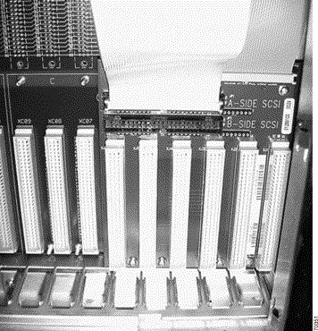
Step 5 Using the other end with the four terminators, connect the last terminator to the backplane of the IPRC card.
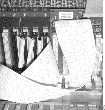
Step 6 If there is more than one IPRC, connect each additional IPRC to one of the terminators on the SCSI cable. An example set of connections is shown in Figure 2-3. In this example, four IPRCs are mounted in the VCO/4K chassis.
 |
Note The example shown in Figure 2-3 is for a nonredundant configuration. For redundancy, an IPRC can be connected to the A-side SCSI, and a redundant IPRC can be connected to the B-side SCSI. |
Step 7 Reinstall the Storage/Control I/O modules.
Step 8 Return power to the VCO/4K.
To install an IPRC in an SDS or VCO/80, perform the following steps:
Step 1 Turn off the power to the SDS or VCO/80 at the main breaker.
Step 2 Remove the disk SCSI cable from the J2 adapter board on the back side of the VME backplane.
 |
Caution Be careful not to damage the SCSI cable and the retaining clips on the adapter board. |
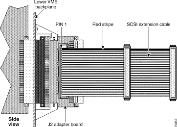
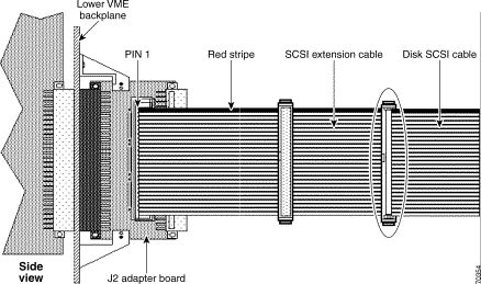
Step 3 Install the Cisco-supplied 6-inch SCSI Extension Cable onto the J2 adapter board, making sure that Pin 1 of the cable is up. Pin 1 is indicated by the red stripe on the cable. See Figure 2-4 for an illustration of this connection.
 |
Caution Be careful not to install the cable upside down. If the cable is improperly installed, the fuse on the J2 adapter board will blow. |
Step 4 Install the disk SCSI cable into the end socket of the SCSI Extension Cable. Again, make sure that
Pin 1 is aligned properly (see Figure 2-5).
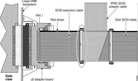
Step 5 Install the IPRC SCSI Adapter Cable into the middle socket of the SCSI Extension Cable. Make sure that Pin 1 is aligned properly (see Figure 2-6).
Step 6 Install the other end of the IPRC SCSI Adapter Cable into the J3 socket for the slot containing the IPRC card.
 |
Caution Be sure to install the IPRC SCSI Adapter Cable into the slot containing the IPRC only. Installing the cable into any other slot will cause the SCSI interface to fail. |
 |
Caution The IPRC SCSI Adapter Cable has four connectors on the end that plugs into the J3 sockets. Use only the connector at the end of the cable. |
Step 7 Power up the SDS or VCO/80 system.
Use the IPRC Card Configuration screen to define IPRC configuration parameters. This screen provides fields in which you specify the length of time after which to chop the end of a newly recorded prompt, the interval timer for checksum verification, and the prompt libraries supported by the card. The IPRC Card Configuration screen also contains fields that display information such as rack position and card operating state.
This screen also provides fields that enable you to control the configuration of the port density for the IPRC when one is added to the system. You can configure 64 and 128- port IPRCs in 8-port increments, to support less than the physical port capacity through the IPRC Card Configuration screen. Field processing for this option allocates or deallocates time slots for the IPRC based on the number of ports you define for the card. Field processing also prevents you from configuring a limited-port IPRC card with more ports than the physical limit.
For information about the IPRC Card Configuration screen and a description of each of its fields, refer to the Cisco VCO/4K System Administrator's Guide.
 |
Note Due to the potential reallocation of time slots and removal of prompt information loaded on the IPRC, you must remove the IPRC from service prior to making any changes on this screen. |
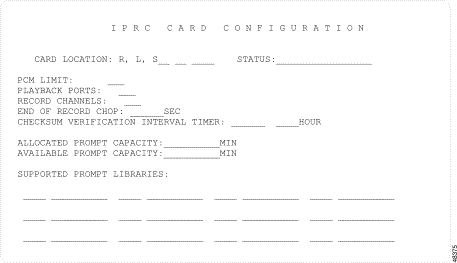
From the Administrator Main Menu, choose Database Administration Menu (A). From the Database Administration Menu, choose Card Summary (A). In the Card Summary screen, press the Next Screen key until you see the Prompt/Record card listed.
Press Next Field until the cursor is located in the Display Card field opposite the Prompt/Record card. Type any character and press Enter.
The following procedure describes how to copy prompts from a floppy diskette onto the VCO/4K hard drive.
Step 1 Log in to the VCO/4K.
Step 2 Insert the diskette containing the prompts into the floppy disk drive in the VCO/4K.
Step 3 In the Administrator Main Menu, type C for the Maintenance menu, and press Enter.
Step 4 If you are creating a new prompt library, proceed to step 5.
If you are modifying an existing prompt library, proceed to step 10.
Step 5 Type J and press Enter to bring up the Create Directory screen. The cursor is located in the screen's data entry field.
Step 6 Type the following directory:
For each additional voice prompt directory you want to create, type
Step 7 Press Enter. The following message appears at the bottom of the screen while the directory is being created:
Step 8 Press Main Menu to return to the Administrator Main Menu.
Step 9 Type C for the Maintenance Menu and press Enter.
Step 10 In the Maintenance Menu press J for the Prompt Library Maintenance screen.
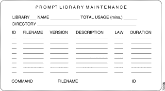
Step 11 In the Library field, type a number for the new or existing library. You may have up to 16 prompt libraries per IPRC.
Step 12 Press Next Field. You may optionally enter a name for the library in the Name field.
Once you have established a number and name for a library, each time you subsequently enter the library number, its name, directory, and prompts will automatically display in the Prompt Library Maintenance screen.
This step sorts prompts in numerical order and displays the list of prompts to be downloaded to the IPRC.
 |
Note When adding a new or modified prompt, or after copying prompts onto the hard disk for the first time, check that the prompt ID numbers are sequential. If there are duplicate ID numbers, either delete the duplicate prompt file that is no longer needed or renumber the prompt file with the EDIT function in the Prompt Library Maintenance screen. |
![]()
![]()
![]()
![]()
![]()
![]()
![]()
![]()
Posted: Sun Sep 29 01:18:55 PDT 2002
All contents are Copyright © 1992--2002 Cisco Systems, Inc. All rights reserved.
Important Notices and Privacy Statement.