|
|

This chapter describes Cisco's implementation of SDLC to LLC2 Media Translation, also known as SDLLCTM. The topics covered in this chapter include:
SDLLC is Cisco's term for media translation between IBM's Synchronous Data Link Control (SDLC) data link protocol for serial lines and ISO's Logical Link Control (LLC) Type 2 data link protocol used over Token Ring networks. The media conversion occurs between Token Ring and serial lines. The protocol conversion occurs between LLC Type 2 protocol used over Token Rings and the SDLC protocol used by IBM machines in an SNA network over serial lines. Any router that supports bridging can support the translation between SDLC on serial links and LLC2 on Token Rings using SDLLC.
Further examples of configuration and usage of SDLLC are found in Cisco Systems' SDLLC Application Note.
SDLLC supports two modes of connections:
In some situations, you may discover that default settings for LLC2 configurations may not be acceptable. In such a case, you may configure LLC2 for optimal use. The chapter "LLC2 and SDLC Link-Level Support" describes the LLC2 commands and how you can use them to optimize your network performance. You can significantly improve network performance by carefully using these commands.
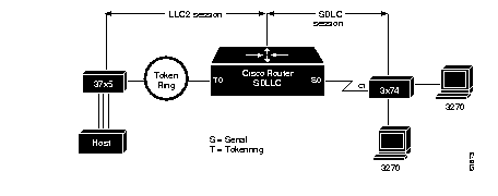
Figure 1-1 illustrates a simple configuration of a Front End Processor (37x5) on a Token Ring and a cluster controller (3x74) on a serial line communicating with each other through a Cisco router containing SDLLC software. The two IBM end nodes do not know that their partners are on different media talking a different protocol; that is, the 37x5 thinks that the 3x74 it is talking to is on a Token Ring, and the 3x74 thinks that the 37x5 it is talking to is on a serial line.

A complete LLC2 session is maintained between the IBM Token Ring node and the Cisco router. The LLC2 session terminates at the Cisco router. Similarly, a complete SDLC session is maintained between the Cisco router and the SDLC station. The SDLC session also terminates at the Cisco router. The first release of SDLLC requires the SDLC station on the serial line to be a secondary node of an SDLC session. End nodes on the Token Rings must be configured to be the primary node, and end nodes on the serial links must be configured as secondary nodes.
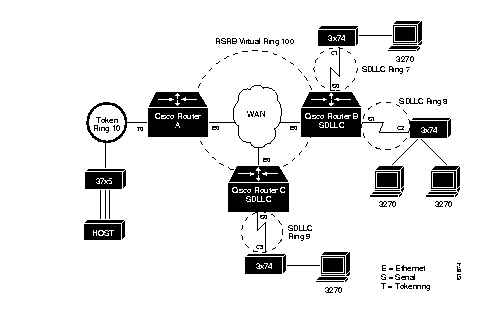
The two end IBM nodes need not be directly connected through their respective media to each other through a Cisco router, but could be separated by a wide area backbone network, as shown in Figure 1-2. Remote source-route bridging (RSRB) would be used to transport packets between Cisco Router A and Cisco Router B, and Cisco Router B performs all conversion between the Token Ring and serial media. This configuration also illustrates that only the Cisco router attached to the serial line (Cisco Router B) needs to be configured for SDLLC. Both Cisco Router A and Cisco Router B would be configured for normal remote source-route bridging. Support for multiple serial lines is provided, limited only by the Cisco hardware used to attach to the serial devices. Only Cisco routers directly attached to the SDLC devices need to be configured with SDLLC commands.
As the IBM node on the Token Ring thinks it is talking to its partner also on a Token Ring, every station hooked to a serial line is assigned a virtual Token Ring address (VTRA). The virtual Token Ring addresses, like real Token Ring addresses, must be unique across the network. (In normal SNA networks, even real Token Ring devices have locally administered addresses, so the system administrators are well versed in address assignments.) In addition to providing a VTRA, a virtual ring number (SDLLC virtual ring number) also needs to be provided as this virtual Token Ring station (actually the serial station) appears to be connected to a virtual ring. The SDLLC virtual ring number is different from virtual ring group numbers used by remote source-route and multiport bridging.
The IBM node on the Token Ring must be aware of the virtual token address of the serial station as it will be a part of its configuration. The VRTA and the SDLLC virtual ring number would be a part of the SDLLC configuration on the Cisco router. When the IBM node on the Token Ring sends out explorers with the VRTA as its destination address in the MAC header, the Cisco router configured with the VTRA intercepts the frame, fills in both the SDLLC virtual ring number and the bridge number in the Routing Information Field (RIF), and sends the response back to the IBM Token Ring node.
There is also a mismatch in the frame sizes supported by the two media. IBM nodes on Token Ring media normally use frame sizes greater than 1K, whereas IBM nodes on serial lines normally limit frame sizes to 265 or 521 bytes. To reduce traffic on backbone networks and provide better performance, it is recommended that nodes on Token Rings send as large a frame as possible. The Cisco router would then segment the frames into multiple data frames and forward them to the SDLC station. No assembly or fragmentation of frames is done when they are forwarded from the SDLC station.
When using SDLLC Media Translation, you may choose any remote source-route bridging (RSRB) encapsulation between the Cisco routers that connect the two IBM end nodes.
With SDLLC Media Translation, the Cisco router attached to the SDLC-speaking station terminates the LLC2 session and translates it into the SDLC session. Figure 1-2 is an example of this network configuration.

Follow these steps to configure SDLLC:
Step 1: Ensure that source-route bridging is enabled on your router/bridge. (This is covered in the chapter "Configuring Source-Route Bridging.")
Step 2: Determine the serial interfaces that you are going to attach to your SDLC-speaking devices and configure them for SDLC.
Step 3: Configure these same interfaces for SDLLC with the sdllc traddr command.
Step 4: Specify any optional sdllc commands for the interface.
Remember the following when configuring SDLLC:
To support device-initiated connections for SDLLC, you must specify the sdllc partner command. This is an interface subcommand that must be specified for the serial line that is attached to the serial line device.
sdllc partner mac-address sdlc-addressBoth the MAC address of the Token Ring host and the SDLC serial line address are required to initiate connections with the Token Ring host. The argument mac-address is the 48-bit MAC address of the Token Ring host. It is written as a dotted triple of four-digit hexadecimal numbers. The sdlc-address argument is the SDLC address of the serial device that will communicate with the Token Ring host. These two devices talk to each other through the Cisco router.
Although the device is said to initiate connections, the router actually initiates connections with the Token Ring host on behalf of the serial device. As part of the SDLLC implementation, the serial device "thinks" that it is communicating with a host also on a serial line. It is actually the router that does all the frame and protocol conversions between serial and Token Ring devices.
There are two conditions under which a router will attempt to initiate a connection to a host on behalf of a serial device:
The router will continue trying once a minute to initiate a connection whenever one of these two conditions is met, until the host responds to its requests. When you no longer want the router to initiate connections with a host, use the no sdllc partner command.
The following required commands apply only to situations where SDLC is enabled on an interface to support SDLLC Media Translation. All of the commands are serial-interface specific.
sdllc traddr xxxx.xxxx.xx00 lr bn trThe sdllc traddr command enables the use of SDLLC Media Translation on this serial interface. The address specified is a MAC address to be assigned to the serial station. The no version of this command disables SDLLC Media Translation on the interface.
Every control unit (3x74) hooked off the serial line will require a virtual Token Ring MAC address (VTRA).This is usually assigned by the system administrator as a locally administered address (unique across the network).
The last byte, that is, the last two hex digits of the address must be 00. This last byte will contain the SDLC address of the station on the serial link, to help support multipoint configurations and debugging of problems. This is shown in the example below.
The variables lr, bn, and tr represent the SDLLC virtual ring number, bridge number, and target ring number respectively which you assign to the interface. In design, the serial interface appears to be a ring, lr, on a source-route bridged network, and ties in through the bridge, bn, to the virtual ring-group, tr. This provides access to other, real rings, through remote source-route bridging source-bridge remote-peer commands. Note that SDLLC can be configured on a router containing no Token Ring interface cards.
The sdllc traddr command automatically turns on the LLC2 process with default values. To change any of the LLC2 parameters (described in the chapter "LLC2 and SDLC Link-Level Support"), specify their values on the serial interface that is being enabled for SDLLC. This is done on the serial interface even though LLC2 does not technically run on the serial interface, but on the SDLLC virtual ring associated with the serial interface. LLC2 commands can be configured after specifying the sdllc traddr command. Some examples follow.
Assume a host wants to talk to two 3174s that its front end processor (FEP) sees as two hosts on a Token Ring, but that are really SDLC devices c1 and c2 off a serial link through a remote router, as was shown in Figure 1-2.
To support SDLLC, the sole Cisco router would have the following configuration:
source-bridge ring-group 100
source-bridge remote-peer 100 tcp 131.108.1.1
source-bridge remote-peer 100 tcp 131.108.2.2
interface tokenring 0
ip address 131.108.2.2 255.255.255.0
source-bridge 1 1 100
interface serial 0
encapsulation sdlc-primary
sdlc address c1
sdllc traddr 0110.2222.3300 8 1 100
llc2 akmax 1
The above configuration does the following:
In the setup shown in Figure 1-2, the following configuration could be used.
The Cisco Router A needs no SDLLC configuration:
source-bridge ring-group 100
source-bridge remote-peer 100 tcp 131.108.1.1
source-bridge remote-peer 100 tcp 131.108.2.2
interface tokenring 0
ip address 131.108.1.1 255.255.255.0
source-bridge 1 1 100
source-bridge spanning
interface ethernet 0
ip address 131.108.2.1 255.255.255.0
The Cisco Router B has the SDLLC configuration:
source-bridge ring-group 100
source-bridge remote-peer 100 tcp 131.108.1.1
source-bridge remote-peer 100 tcp 131.108.2.2
interface ethernet 0
ip address 131.108.2.2 255.255.255.0
interface serial 0
encapsulation sdlc-primary
sdlc address c1
sdllc traddr 0110.2222.3300 8 1 100
interface serial 1
encapsulation sdlc-primary
sdlc address c2
sdllc traddr 0220.3333.4400 9 1 100
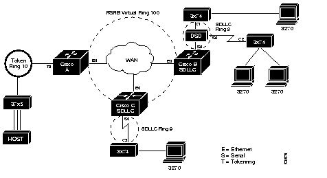
SDLLC also supports multipoint on the SDLC link; that is, a data-sharing device (DSD) may be used, as illustrated in Figure 1-3.

The configuration to support this would be the same as given before on Cisco Router A, but on Cisco Router B would now read as:
source-bridge ring-group 100
source-bridge remote-peer 100 tcp 131.108.1.1
source-bridge remote-peer 100 tcp 131.108.2.2
interface ethernet 0
ip address 131.108.2.2 255.255.255.0
interface serial 0
encapsulation sdlc-primary
sdlc address c1
sdlc address c2
sdllc traddr 0110.2222.3300 8 1 100
The sdllc sdlc-largest-frame command indicates the largest information frame (I-frame) size that can be sent or received by the SDLC station at address address. The following is the command syntax:
sdllc sdlc-largest-frame address valueMost SDLC devices are limited to 265 bytes. The default value for this is 265. This default behavior can be retrieved by specifying the no version of the command. I-frames received from the Token Ring station that are larger than this will be properly fragmented.
The sdllc ring-largest-frame command indicates the largest I-frame size that can be sent or received from the LLC2 primary station. The following is the command syntax:
sdllc ring-largest-frame valueThe possible values for this are the same as are possible for the largest-frame parameter of the source-bridge remote-peer command. The default value for this is 516. This default behavior can be retrieved by specifying the no version of the command.
The sdllc xid command allows you to specify an XID value to be associated with the SDLC station at address address. This value is used to reply to XIDs received on the Token Ring (LLC2) side of the connection. An XID request and responses are usually exchanged before sessions are started.
Be sure that the XID configured on the Cisco router matches the IDBLKNUM configured on the host. The XID response to an XID request from the Token Ring host will contain the information you configured in the sdllc xid subcommand. The host will check the XID response it receives with the IDBLKNUM (that is configured in the NCP). If they match, the Token Ring host will initiate a session with the Cisco router. If they do not match, the host will not initiate a session with the Cisco router. The XID must by four bytes (eight digits) in length, and is specified with hexadecimal digits.
The following is the command syntax:
sdllc xid address xxxxxxxxThe no version of this command disables XID processing for this address.
This section describes the EXEC commands you use to monitor the state of SDLLC.
show llc2 The show llc2 command shows the state of the LLC2 connections associated with SDLLC.
the chapter "LLC2 and SDLC Link-Level Support" describes the output of this command. Look for the LLC2 connections which correspond to the MAC addresses you assigned to the SDLLC interfaces with the sdllc traddr command.
This command shows the SDLLC statistics for SDLLC configured interfaces. An example of output follows:
Serial 0 is up, line protocol is up
  Hardware is MCI Serial
  MTU 1500 bytes, BW 1544 Kbit, DLY 20000 usec, rely 255/255, load 1/255
  Encapsulation SDLC-PRIMARY, loopback not set
      Timers (msec): poll pause 100 fair poll 500. Poll limit 1
      [T1 3000, N1 12016, N2 20, K 7] timer: 56608 Last polled device: none
      SDLLC [ma: 0000.0C01.14--, ring: 7 bridge: 1, target ring: 10
             largest token ring frame 2052]
  SDLC addr C1 state is CONNECT
      VS 6, VR 3, RCNT 0, Remote VR 6, Current retransmit count 0
      Hold queue: 0/12 IFRAMEs 77/22 RNRs 0/0 SNRMs 1/0 DISCs 0/0
      Poll: clear, Poll count: 0, chain: p: C1 n: C1
      SDLLC [largest SDLC frame: 265, XID: disabled]
  Last input 00:00:02, output 00:00:01, output hang never
  Output queue 0/40, 0 drops; input queue 0/75, 0 drops
  Five minute input rate 517 bits/sec, 30 packets/sec
  Five minute output rate 672 bits/sec, 20 packets/sec
     357 packets input, 28382 bytes, 0 no buffer
     Received 0 broadcasts, 0 runts, 0 giants
     0 input errors, 0 CRC, 0 frame, 0 overrun, 0 ignored, 0 abort
     926 packets output, 77274 bytes, 0 underruns
     0 output errors, 0 collisions, 0 interface resets, 0 restarts
     2 carrier transitions
Most of the above output is generic to all SDLC encapsulated interfaces and is described in the chapter "LLC2 and SDLC Link-Level Support." Table 1-1 shows the parameters specific to SDLLC.
| Parameter | Description |
|---|---|
| SDLLC ma | Lists the MAC address configured for this interface. The last byte is shown as "--" to indicate that it is filled in with the SDLC address of the connection. |
| ring, bridge, target ring | Lists the parameters as configured by the sdllc traddr command |
| largest token ring frame | Shows the largest Token Ring frame that is accepted on the LLC2 side of the connection |
| largest SDLC frame | Shows the largest SDLC frame that is accepted and will be generated on the SDLC side of the connection |
| XID | enabled or disabled: Shows whether XID processing is enabled on the SDLC side of the connection. If enabled, it will show the XID value for this address. |
This command shows state transition information on SDLLC Media Translation. This information is primarily useful to Cisco support and development staff. The debugging output may be disabled with the undebug command.
Following is an alphabetical list of the SDLLC interface subcommands that specify parameters for interfaces configured for SDLLC Media Translation. These commands must follow an interface command.
[no] sdllc traddr xxxx.xxxx.xx00 lr bn tr
Enables the use of SDLLC on a serial interface. The address is a MAC address to be assigned to the serial interface. The variables lr, bn, and tr represent the SDLLC virtual ring number, bridge number, and target ring number respectively which you assign to the interface.
[no] sdllc sdlc-largest-frame address value
Indicates the largest I-frame size that can be sent or received by the SDLC station at address address. The variable value is the size in bytes, with the default being 265 bytes.
[no] sdllc ring-largest-frame value
Indicates the largest I-frame size that can be sent or received by the LLC2 side of the SDLLC connection. The possible values for this are the same as are possible for the largest-frame parameter of the source-bridge remote-peer command. The default value is 516 bytes.
[no] sdllc xid address xxxxxxxx
Specifies an XID value to be associated with the SDLC station at address address.This value is used to reply to XIDs received on the Token Ring (LLC2) side of the connection. The default is not to support XIDs. The XID must by four bytes (eight digits) in length, and is specified with hexadecimal digits.
|
|