|
|

Table Of Contents
Layer 2 Tunnel Protocol Version 3
Prerequisites for Layer 2 Tunnel Protocol Version 3
Restrictions for Layer 2 Tunnel Protocol Version 3
Supported Port Adapters for the Cisco 7200 Series and Cisco 7500 Series Routers
Cisco 7200 Series-Specific Restrictions
Cisco 7301 Specific Restrictions
Cisco 7304 Specific Restrictions
Cisco 7500 Series-Specific Restrictions
Cisco 10720-Specific Restrictions
Cisco 12000 Series-Specific Restrictions
Frame Relay-Specific Restrictions
ATM VP Mode Single Cell Relay over L2TPv3 Restrictions
ATM AAL5 SDU over L2TPv3 and Single Cell Relay VC Mode over L2TPv3 Restrictions
ATM Port Mode Cell Relay over L2TPv3 Restrictions
ATM Cell Packing over L2TPv3 Restrictions
Protocol Demultiplexing for L2TPv3 Restrictions
L2TPv3 Control Message Hashing Restrictions
L2TPv3 Digest Secret Graceful Switchover Restrictions
Quality of Service Restrictions in L2TPv3 Tunneling
Information About Layer 2 Tunnel Protocol Version 3
L2TPv3 and UTI Feature Comparison
How to Configure Layer 2 Tunnel Protocol Version 3
Configuring L2TP Control Channel Parameters
Configuring the L2TPv3 Pseudowire
Configuring the Xconnect Attachment Circuit
Manually Configuring L2TPv3 Session Parameters
Configuring the Xconnect Attachment Circuit for ATM VP Mode Single Cell Relay over L2TPv3
Configuring the Xconnect Attachment Circuit for ATM Single Cell Relay VC Mode over L2TPv3
Configuring the Xconnect Attachment Circuit for ATM Port Mode Cell Relay over L2TPv3
Configuring the Xconnect Attachment Circuit for ATM Cell Packing over L2TPv3
Configuring the Xconnect Attachment Circuit for ATM AAL5 SDU Mode over L2TPv3
Configuring OAM Local Emulation for ATM AAL5 over L2TPv3
Configuring Protocol Demultiplexing for L2TPv3
Manually Clearing L2TPv3 Tunnels
Configuration Examples for Layer 2 Tunnel Protocol Version 3
Configuring a Static L2TPv3 Session for an Xconnect Ethernet Interface: Example
Configuring a Negotiated L2TPv3 Session for an Xconnect VLAN Subinterface: Example
Configuring a Negotiated L2TPv3 Session for Local HDLC Switching: Example
Verifying an L2TPv3 Session: Example
Verifying an L2TP Control Channel: Example
Configuring L2TPv3 Control Channel Authentication: Examples
Configuring L2TPv3 Digest Secret Graceful Switchover: Example
Verifying L2TPv3 Digest Secret Graceful Switchover: Example
Configuring a Pseudowire Class for Fragmentation of IP Packets: Example
Configuring ATM VP Mode Single Cell Relay over L2TPv3: Example
Verifying ATM VP Mode Single Cell Relay over L2TPv3 Configuration: Example
Configuring ATM Single Cell Relay VC Mode over L2TPv3: Example
Verifying ATM Single Cell Relay VC Mode over L2TPv3: Example
Configuring ATM Port Mode Cell Relay over L2TPv3: Example
Configuring ATM Cell Packing over L2TPv3: Examples
Configuring ATM AAL5 SDU Mode over L2TPv3: Examples
Verifying ATM AAL5 SDU Mode over L2TPv3 Configuration: Examples
Configuring OAM Local Emulation for ATM AAL5 over L2TPv3: Examples
Verifying OAM Local Emulation for ATM AAL5 over L2TPv3 Configuration: Examples
Configuring Protocol Demultiplexing for L2TPv3: Examples
Manually Clearing an L2TPv3 Tunnel: Example
Configuring Frame Relay DLCI-to-DLCI Switching: Example
Configuring Frame Relay Trunking: Example
Configuring QoS for L2TPv3 on the Cisco 7500 Series: Example
Configuring QoS for L2TPv3 on the Cisco 12000 Series: Examples
Configuring a QoS Policy for Committed Information Rate Guarantees: Example
Setting the Frame Relay DE Bit Configuration: Example
Matching the Frame Relay DE Bit Configuration: Example
Configuring MLFR for L2TPv3 on the Cisco 12000 Series: Example
Configuring an MQC for Committed Information Rate Guarantees: Example
clear l2tun counters tunnel l2tp
monitor l2tun counters tunnel l2tp
show l2tun counters tunnel l2tp
snmp-server enable traps l2tun pseudowire status
snmp-server enable traps l2tun session
xconnect logging pseudowire status
Layer 2 Tunnel Protocol Version 3
The Layer 2 Tunnel Protocol Version 3 feature expands on Cisco support of the Layer 2 Tunnel Protocol Version 3 (L2TPv3). L2TPv3 is an Internet Engineering Task Force (IETF) l2tpext working group draft that provides several enhancements to L2TP for the capability to tunnel any Layer 2 payload over L2TP. Specifically, L2TPv3 defines the L2TP protocol for tunneling Layer 2 payloads over an IP core network using Layer 2 virtual private networks (VPNs). Benefits of this feature include the following:
•
L2TPv3 simplifies deployment of VPNs.
•
•
History for the Layer 2 Tunneling Protocol Version 3 Feature
12.0(21)S
Initial data plane support for L2TPv3 was introduced on the Cisco 7200 series, Cisco 7500 series, Cisco 10720, and Cisco 12000 series platforms.
12.0(23)S
L2TPv3 control plane support was introduced on the Cisco 7200 series, Cisco 7500 series, Cisco 10720, and Cisco 12000 series platforms.
12.0(24)S
L2TPv3 was enhanced to support the Layer 2 Fragmentation feature (fragmentation of IP packets before they enter the pseudowire) on the Cisco 7200 series, Cisco 7500 series, and Cisco 12000 series Internet routers.
12.0(25)S
Support was added for the ATM VP Mode Single Cell Relay over L2TPv3 feature on the Cisco 7200 and Cisco 7500 series routers with ATM Deluxe PA-A3 interfaces.
L2TPv3 control plane support was introduced on the Cisco 12000 series 1-port channelized OC-12 (DS3) line card.
12.0(23)S3
L2TPv3 control plane support was introduced on the Cisco 12000 series 1-port channelized OC-12 (DS3) line card.
12.0(24)S1
L2TPv3 control plane support was introduced on the Cisco 12000 series 1-port channelized OC-12 (DS3) line card.
12.0(27)S
Support was added for the following features to Cisco 12000 series 2-port channelized OC-3/STM-1 (DS1/E1) and 6-port Channelized T3 (T1) line cards:
•
•
12.0(28)S
Support was added for the following features on the Cisco 7200 series and Cisco 7500 series routers:
•
•
•
•
12.0(29)S
Support was added for the following features:
•
•
•
•
•
12.0(30)S
Support was added for the following features to Cisco IOS Release 12.0(30)S:
•
•
•
Support was added for native L2TPv3 tunneling on IP services engine (ISE) line cards on the Cisco 12000 series Internet router.
12.0(31)S
Support was added for the following feature to Cisco IOS Release 12.0(31)S:
•
Support was added for native L2TPv3 tunneling on the following ISE line cards on the Cisco 12000 series Internet router:
•
–
–
–
–
•
12.0(31)S2
Support was added for customer-facing IP Services Engine (ISE) interfaces configured for Layer 2 local switching on a Cisco 12000 series Internet router (see Layer 2 Local Switching).
12.0(32)SY
Support was added for Engine 5 line cards — shared port adapters (SPAs) and SPA interface processors (SIPs) — on the Cisco 12000 series Internet router, including:
•
•
Support was added for the L2TPv3 Layer 2 fragmentation feature on the Cisco 10720 Internet router.
12.2(25)S
Support was added for the following features to Cisco IOS Release 12.2(25)S:
•
•
•
•
•
•
•
12.2(25)S4
Support was added for the following features on the Cisco 7304 NPE-G100 and the Cisco 7304 NSE-100:
•
•
•
•
•
•
Support was added for this feature on the Cisco 7304 NPE-G100 only:
•
12.2(27)SBC
Support was added for the following features:
•
•
•
•
12.3(2)T
This feature was integrated into Cisco IOS Release 12.3(2)T and implemented on the Cisco 2600XM series Multiservice platforms, the Cisco 2691 Multiservice routers, the Cisco 3662 Multiservice Access platforms, the Cisco 3725 Modular Access routers, and the Cisco 3745 Modular Access routers.
12.4(11)T
Support was added for the following features:
•
•
•
Finding Support Information for Platforms and Cisco IOS and Catalyst OS Software Images
Use Cisco Feature Navigator to find information about platform support and Cisco IOS and Catalyst OS software image support. To access Cisco Feature Navigator, go to http://www.cisco.com/go/cfn. An account on Cisco.com is not required.
Contents
•
•
•
•
•
•
Prerequisites for Layer 2 Tunnel Protocol Version 3
•
•
•
Restrictions for Layer 2 Tunnel Protocol Version 3
The following subsections contain information on restrictions:
•
•
•
•
•
•
•
•
•
•
•
•
•
•
•
•
Supported Port Adapters for the Cisco 7200 Series and Cisco 7500 Series Routers
The following port adapters support L2TPv3 on the Cisco 7200 series and Cisco 7500 series routers:
•
•
•
•
•
•
•
•
•
•
•
•
•
•
•
•
•
•
•
•
•
•
•
•
•
•
•
•
•
•
•
The following port adaptors support L2TPv3 on the Cisco 7200 series routers only:
•
•
General L2TPv3 Restrictions
•
•
•
When L2TPv3 is used to tunnel Frame Relay D channel data-link connection identifiers (DLCIs), an IDB is not required for each circuit. As a result, the memory requirements are much lower. The scalability targets for the Engineering Field Test (EFT) program are 4000 L2TP session.
•
•
•
•
•
•
Cisco 7200 Series-Specific Restrictions
•
•
•
Cisco 7301 Specific Restrictions
•
•
Cisco 7304 Specific Restrictions
•
•
•
Cisco 7500 Series-Specific Restrictions
•
•
•
Cisco 10720-Specific Restrictions
•
•
•
•
•
You can also configure a LAN interface as the IP local interface so that the tunnel control session is tied to an operational LAN (Gigabit Ethernet or Fast Ethernet) interface or subinterface. However, in this case, the tunnel control plane is used only as long as the Gigabit Ethernet or Fast Ethernet interface is operational.
Cisco 12000 Series-Specific Restrictions
Tunnel Server Card Versus Native L2TPv3 Implementation
On the Cisco 12000 series Internet router, L2TPv3 is implemented in two different ways:
•
•
Note
Different combinations of engine types are supported as customer-facing and backbone-facing line cards for encapsulation and decapsulation in L2TPv3 tunneling.
L2TPv3 Encapsulation
When a Layer 2 packet arrives on a customer-facing interface, if the interface is bound to an L2TPv3 tunnel, L2TPv3 encapsulation is supported as follows:
•
•
A backbone-facing line card of any engine type sends the packet across the service provider backbone network.
L2TPv3 Decapsulation
When an L2TPv3 packet arrives on a backbone-facing interface, L2TPv3 decapsulation is supported as follows:
•
–
–
•
–
–
Note
- The customer-facing line card is Engine 2 or an earlier engine line card.
- The customer-facing line card is ISE/E5 and the backbone-facing line card is non-ISE/5.
In these cases, packets received on the backbone-facing interface are dropped. The following warning message is logged: L2TPv3 decapsulation packet dropped.Cisco 12000 Series Line Cards—General Restrictions
•
•
•
•
–
–
–
–
•
•
Engine 2 and Earlier Engine-Specific Restrictions
•
•
To configure the server card, you must enter the ip unnumbered command and configure the IP address on the PoS interface of the server card before you configure hardware modules. Then enter the hw-module slot slot-number mode server command.
This initial configuration makes the server card IP-aware for backbones requiring an Address Resolution Protocol (ARP) to be generated by the line card. The backbone types that require this configuration are Ethernet and Spatial Reuse Protocol (SRP).
This configuration is also a requirement for session keepalives. The interface port of the server card is automatically set to loopback internal and no keepalives when the hw-module slot slot-number mode server command is configured.
Note
•
–
–
–
•
•
•
•
•
•
•
•
•
•
–
–
Edge Line Card-Specific Restrictions
The following restrictions apply to L2TPv3 sessions configured on IP Services Engine (ISE) and Engine 5 edge line cards:
•
To configure the feature mode, enter the hw-module slot slot-number np mode feature command. You cannot unconfigure the feature mode on a customer-facing ISE/E5 line card until all L2TPv3 xconnect attachment circuits on the line card are removed.
A backbone-facing ISE/E5 line card can operate in any mode and no special feature mode configuration is required.
•
•
•
This means that if you enter the ip pmtu command to enable the discovery of a path maximum transmission unit (PMTU) for L2TPv3 traffic, and a customer IP packet exceeds the PMTU, IP fragmentation is not performed on the IP packet before L2TPv3 encapsulation. These packets are dropped. For more information, see L2TPv3 Layer 2 Fragmentation.
Table 1 and Table 2 show the ISE and E5 interfaces that are supported in a native L2TPv3 tunnel on:
•
•
Table 1 ISE Interfaces Supported in a Native L2TPv3 Tunnel Session
4-port OC-3 POS ISE
Supported
Supported
8-port OC-3 POS ISE
Supported
Supported
16-port OC-3 POS ISE
Supported
Supported
4-port OC-12 POS ISE
Supported
Supported
1-port OC-48 POS ISE
Supported
Supported
1-port channelized OC-12 (DS1) ISE
Supported
Not supported
2.5G ISE SPA Interface Processor1 :
•
•
•
•
Supported
Not supported
1-port channelized OC-48 POS ISE
Not supported
Not supported
4-port OC-3 ATM ISE
Supported
Supported
4-port OC-12 ATM ISE
Supported
Supported
4-port Gigabit Ethernet ISE 2
Supported
Supported
1 For more information about the shared port adapters (SPAs) and SPA interface platforms (SIPs) supported on Cisco 12000 series routers, refer to the Cisco 12000 Series Routers SPA Hardware Installation Guide.
2 The 4-port Gigabit Ethernet ISE line card supports VLAN membership (port-based and VLAN-based) in a native L2TPv3 tunnel session on customer-facing and backbone-facing interfaces. See 802.1q (VLAN) for more information.
Table 3 describes the L2TPv3 features supported in a native L2TPv3 tunnel session and the customer-facing ISE/E5 line cards that support each feature. Note that although native L2TPv3 sessions do not support L2TPv3 Layer 2 (IP packet) fragmentation and slow-path switching features, ATM (as a transport type) and QoS features (traffic policing and shaping) across all media types are supported.
Table 3 L2TPv3 Features Supported in a Native L2TPv3 Session
Native L2TPv3 tunneling (fast-path)
Supports the same L2TPv3 features that are supported by server card-based L2TPv3 tunneling, except that L2TPv3 Layer 2 (IP packet) fragmentation is not supported.
For more information, see the " L2TPv3 Features" section.
4-port OC-3 POS ISE
8-port OC-3 POS ISE
16-port OC-3 POS ISE
4-port OC-12 POS ISE
1-port OC-48 POS ISE
4-port OC-3 ATM ISE
4-port OC-12 ATM ISE
4-port Gigabit Ethernet ISE
1-port channelized OC-12 (DS1) ISE
ISE SPAs:
- 2-port T3/E3 Serial
- 4-port T3/E3 Serial
- 2-port channelized T3 to DS0
- 4-port channelized T3 to DS0Engine 5 SPAs:
- 1-port channelized STM-1c/OC-3c to DS0
- 8-port channelized T1/E1
- 8-port fast Ethernet
- 5-port Gigabit Ethernet
- 10-port Gigabit Ethernet
- 4-port OC-3/STM4 POS
- 8-port OC-3/STM4 POS
- 2-port OC-12/STM4 POS
- 4-port OC-12/STM4 POS
- 8-port OC-12/STM4 POSL2TP class and pseudowire class configuration
You can create an L2TP template of L2TP control channel parameters that can be inherited by different pseudowire classes configured on a PE router.
You can also configure a pseudowire template of L2TPv3 session-level parameters that can be used to configure the transport Layer 2 traffic over an xconnect attachment circuit.
For more information, see the sections " Configuring L2TP Control Channel Parameters" and " Configuring the L2TPv3 Pseudowire."
4-port OC-3 POS ISE
8-port OC-3 POS ISE
16-port OC-3 POS ISE
4-port OC-12 POS ISE
1-port OC-48 POS ISE
4-port OC-3 ATM ISE
4-port OC-12 ATM ISE
4-port Gigabit Ethernet ISE
1-port channelized OC-12 (DS1) ISE
ISE SPAs:
- 2-port T3/E3 Serial
- 4-port T3/E3 Serial
- 2-port channelized T3 to DS0
- 4-port channelized T3 to DS0Engine 5 SPAs:
- 1-port channelized STM-1c/OC-3c to DS0
- 8-port channelized T1/E1
- 8-port Fast Ethernet
- 5-port Gigabit Ethernet
- 10-port Gigabit Ethernet
- 4-port OC-3/STM4 POS
- 8-port OC-3/STM4 POS
- 2-port OC-12/STM4 POS
- 4-port OC-12/STM4 POS
- 8-port OC-12/STM4 POSL2TPv3 tunnel marking and traffic policing on the following types of ingress interfaces, when bound to a native L2TPv3 tunnel session:
- 802.1q (VLAN)
- ATM
- Channelized
- Ethernet
- Frame Relay DLCIsThe following conform, exceed, and violate values for the action argument are supported for the police command when QoS policies are configured on an ISE/E5 ingress interface bound to a native L2TPv3 tunnel.
The set commands can also be used to set the IP precedence or DSCP value in the tunnel header of a L2TPv3 tunneled packet on an ingress interface.
conform-action actions:
set-prec-tunnel
set-dscp-tunnel
transmitexceed-action actions:
drop
set-clp (ATM only)
set-dscp-tunnel
set-dscp-tunnel and set-clp (ATM only)
set-dscp-tunnel and set-frde
(Frame Relay only)
set-frde (Frame Relay only)
set-prec-tunnel
set-prec-tunnel and set-clp (ATM only)
set-prec-tunnel and set-frde
(Frame Relay only)
transmitviolate-action actions:
drop
See " QoS: Tunnel Marking for L2TPv3 Tunnels" for information about how to use the L2TPv3 tunnel marking and traffic policing features on Engine 2 (and earlier engine) interfaces bound to a TSC-based L2TPv3 tunnel session.
4-port OC-3 POS ISE
8-port OC-3 POS ISE
16-port OC-3 POS ISE
4-port OC-12 POS ISE
1-port OC-48 POS ISE
4-port OC-3 ATM ISE
4-port OC-12 ATM ISE
4-port Gigabit Ethernet ISE
1-port channelized OC-12 (DS1) ISE
ISE SPAs:
- 2-port T3/E3 serial
- 4-port T3/E3 serial
- 2-port channelized T3 to DS0
- 4-port channelized T3 to DS0Engine 5 SPAs:
- 1-port channelized STM-1c/OC-3c to DS0
- 8-port channelized T1/E1
- 8-port Fast Ethernet
- 5-port Gigabit Ethernet
- 10-port Gigabit Ethernet
- 4-port OC-3/STM4 POS
- 8-port OC-3/STM4 POS
- 2-port OC-12/STM4 POS
- 4-port OC-12/STM4 POS
- 8-port OC-12/STM4 POSFrame Relay DLCI-to-DLCI tunneling
Frame Relay DLCIs are connected to create an end-to-end Frame Relay PVC. Traffic arriving on a DLCI on one interface is forwarded across an L2TPv3 tunnel to another DLCI on the other interface.
For more information, see "DLCI-to-DLCI Switching" in the " Frame Relay" section.
4-port OC-3 POS ISE
8-port OC-3 POS ISE
16-port OC-3 POS ISE
4-port OC-12 POS ISE
1-port OC-48 POS ISE
1-port channelized OC-12 (DS1) ISE
ISE SPAs:
- 2-port T3/E3 serial
- 4-port T3/E3 serial
- 2-port channelized T3 to DS0
- 4-port channelized T3 to DS0Engine 5 SPAs:
- 1-port channelized STM-1c/OC-3c to DS0
- 8-port channelized T1/E1
- 4-port OC-3/STM4 POS
- 8-port OC-3/STM4 POS
- 2-port OC-12/STM4 POS
- 4-port OC-12/STM4 POS
- 8-port OC-12/STM4 POS
- 2-port OC-48/STM16 POS/RPRATM single cell and packed cell relay: VC mode
Each VC is mapped to a single L2TPv3 tunnel session. The following ATM cell relay modes are supported:
•
•
For more information, see the " ATM" section.
4-port OC-3 ATM ISE
4-port OC-12 ATM ISENot supported
ATM single cell and packed cell relay: VP mode
ATM cells arriving into a predefined PVP on the ATM interface are transported to a predefined PVP on the egress ATM interface. The following ATM cell relay modes are supported:
•
•
For more information, see the " ATM" section.
4-port OC-3 ATM ISE
4-port OC-12 ATM ISENot supported
ATM single cell relay and packed cell relay: Port mode
ATM cells arriving at an ingress ATM interface are encapsulated into L2TPv3 data packets and transported to the egress ATM interface.The following ATM cell relay modes are supported:
•
•
For more information, see the " ATM" section.
4-port OC-3 ATM ISE
4-port OC-12 ATM ISENot supported
ATM AAL5 PVC tunneling
The ATM AAL5 payload of an AAL5 PVC is mapped to a single L2TPv3 session.
For more information, see "ATM AAL5" in the " ATM" section.
4-port OC-3 ATM ISE
4-port OC-12 ATM ISENot supported
OAM emulation mode for ATM AAL5
OAM local emulation mode for ATM AAL5 payloads is supported. Instead of being passed through the pseudowire, OAM cells are terminated and handled locally. On the L2TPv3-based pseudowire, the CE device sends an SLI message across the pseudowire to notify the peer PE node about the defect, rather than tearing down the session.
For more information, see "ATM AAL5 over L2TPv3: OAM Local Emulation Mode" in the " ATM" section.
4-port OC-3 ATM ISE
4-port OC-12 ATM ISENot supported
OAM transparent mode for ATM AAL5
OAM transparent mode for ATM AAL5 payloads is supported. The PE routers pass OAM cells transparently across the L2TPv3 tunnel.
For more information, see "ATM AAL5 over L2TPv3: OAM Transparent Mode" in the " ATM" section.
4-port OC-3 ATM ISE
4-port OC-12 ATM ISENot supported
Ethernet port-to-port tunneling
Ethernet frames are tunneled through an L2TP pseudowire.
For more information, see the " Ethernet" section.
4-port Gigabit Ethernet ISE
Engine 5 SPAs:
- 8-port Fast Ethernet
- 5-port Gigabit Ethernet
- 10-port Gigabit EthernetVLAN-to-VLAN tunneling
The following types of VLAN membership are supported in an L2TPv3 tunnel:
•
•
For more information, see the " 802.1q (VLAN)" section.
4-port Gigabit Ethernet ISE
Engine 5 SPAs:
- 8-port Fast Ethernet
- 5-port Gigabit Ethernet
- 10-port Gigabit EthernetDual rate, 3-Color Marker for traffic policing on Frame Relay DLCIs of ingress interfaces, when bound to a native L2TPv3 tunnel session1
The dual rate, 3-Color Marker in color-aware and color-blind modes, as defined in RFC 2698 for traffic policing, is supported on ingress ISE interfaces to classify packets.
For more information, refer to QoS: Color-Aware Policer."
4-port OC-3 POS ISE
8-port OC-3 POS ISE
16-port OC-3 POS ISE
4-port OC-12 POS ISE
1-port OC-48 POS ISE
4-port Gigabit Ethernet ISE
1-port channelized OC-12 (DS1) ISE
ISE SPAs:
- 2-port T3/E3 serial
- 4-port T3/E3 serial
- 2-port channelized T3 to DS0
- 4-port channelized T3 to DS0Engine 5 SPAs:
- 1-port channelized STM-1c/OC-3c to DS0
- 8-port channelized T1/E1
- 4-port OC-3/STM4 POS
- 8-port OC-3/STM4 POS
- 2-port OC-12/STM4 POS
- 4-port OC-12/STM4 POS
- 8-port OC-12/STM4 POS
- 2-port OC-48/STM16 POS/RPRTraffic shaping on ATM and Frame Relay egress interfaces based on class map configuration is supported.
Traffic shaping is supported on ATM egress interfaces for the following service categories:
•
•
•
•
For more information, see " Traffic Shaping on ATM Line Cards for the Cisco 12000 Series."
4-port OC-3 POS ISE
8-port OC-3 POS ISE
16-port OC-3 POS ISE
4-port OC-12 POS ISE
1-port OC-48 POS ISE
4-port OC-3 ATM ISE
4-port OC-12 ATM ISE
4-port Gigabit Ethernet ISE
1-port channelized OC-12 (DS1) ISE
ISE SPAs:
- 2-port clear channel T3/E3
- 4-port clear channel T3/E3
- 2-port channelized T3 to DS0
- 4-port channelized T3 to DS0Engine 5 SPAs:
- 1-port channelized STM-1c/OC-3c to DS0
- 8-port channelized T1/E1
- 4-port OC-3/STM4 POS
- 8-port OC-3/STM4 POS
- 2-port OC-12/STM4 POS
- 4-port OC-12/STM4 POS
- 8-port OC-12/STM4 POS
- 2-port OC-48/STM16 POS/RPRLayer 2 Virtual Private Network (L2VPN) interworking
L2VPN interworking allows attachment circuits using different Layer 2 encapsulation types to be connected over an L2TPv3 pseudowire.
On an ISE interface configured for L2TPv3 tunneling, the following Layer 2 encapsulations are supported:
ATM AAL5
Ethernet
802.1q (VLAN)
Frame Relay DLCIOn an Engine 5 interface configured for L2TPv3 tunneling, the following Layer 2 encapsulations are supported:
Ethernet
802.1q (VLAN)
Frame Relay DLCI4-port OC-3 POS ISE
8-port OC-3 POS ISE
16-port OC-3 POS ISE
4-port OC-12 POS ISE
1-port OC-48 POS ISE
4-port OC-3 ATM ISE
4-port OC-12 ATM ISE
4-port Gigabit Ethernet ISE
1-port channelized OC-12 (DS1) ISE
ISE SPAs:
- 2-port T3/E3 serial
- 4-port T3/E3 serial
- 2-port channelized T3 to DS0
- 4-port channelized T3 to DS0Engine 5 SPAs:
- 1-port channelized STM-1c/OC-3c to DS0
- 8-port channelized T1/E1
- 8-port Fast Ethernet
- 8-port 10/100 Ethernet
- 1-port 10-Gigabit Ethernet
- 2-port Gigabit Ethernet
- 5-port Gigabit Ethernet
- 10-port Gigabit Ethernet
- 4-port OC-3/STM4 POS
- 8-port OC-3/STM4 POS
- 2-port OC-12/STM4 POS
- 4-port OC-12/STM4 POS
- 8-port OC-12/STM4 POS
- 2-port OC-48/STM16 POS/RPR
- 1-port OC192/STM64 POS/RPR
1 Although the dual-rate, 3-Color Marker policer is not supported on ATM ISE/E5 interfaces, the ATM Forum Traffic Management Version 4.1-compliant Generic Cell Rate Algorithm (GCRA) policer is supported. The GCRA policer uses rate, peak rate, delay tolerance, and ATM maximum burst size, and supports the following options:
- set-dscp-tunnel
- set-dscp-tunnel and set-clp-transmit
- set-prec-tunnel
- set-prec-tunnel and set-clp-transmit2 Note that VBR-rt and CBR share the same high priority shaping. ATM traffic shaping restricts traffic to the maximum rate configured on an ATM VC or PVP with due priority among the respective service categories.
You can configure queue limits for an ATM VC or PVP. The queue limits are dual thresholds in which two different thresholds can be configured for CLP=1 cells and CLP0+1 cells. The CLP1 threshold must be lower than the queue limit threshold so that CLP=1 cells are dropped earlier than CLP=0 cells when packets start to fill the queue.
Frame Relay-Specific Restrictions
•
•
•
•
•
•
•
•
•
•
VLAN-Specific Restrictions
•
•
•
ATM VP Mode Single Cell Relay over L2TPv3 Restrictions
•
•
ATM AAL5 SDU over L2TPv3 and Single Cell Relay VC Mode over L2TPv3 Restrictions
•
•
•
•
•
ATM Port Mode Cell Relay over L2TPv3 Restrictions
•
•
•
ATM Cell Packing over L2TPv3 Restrictions
•
•
Protocol Demultiplexing for L2TPv3 Restrictions
•
•
•
•
•
•
•
•
L2TPv3 Control Message Hashing Restrictions
•
•
L2TPv3 Digest Secret Graceful Switchover Restrictions
•
•
Quality of Service Restrictions in L2TPv3 Tunneling
Quality of service (QoS) policies configured with the modular QoS command-line interface (MQC) are supported in L2TPv3 tunnel sessions with the following restrictions:
Frame Relay Interface (Non-ISE/E5)
•
•
–
•
•
•
•
•
•
–
•
–
•
•
•
—With both a low latency (priority) queue and class-default queue configured. (The low latency queue is supported only in combination with the class-default queue, and cannot be configured with normal distributed round robin (DRR) queues.)
—Without a low latency queue configured. (In this case, only six queues are supported, including the class-default queue.)
•
For an example, see Configuring QoS on a Frame Relay Interface in a TSC-Based L2TPv3 Tunnel Session.
Edge Engine (ISE/E5) Interface
On the Cisco 12000 series, a QoS policy is supported in native L2TPv3 tunnel sessions on ISE/E5 interfaces (see Table 1 and Table 2 for a list of supported line cards) with the following restrictions:
•
conform-action actions:
set-prec-tunnel
set-dscp-tunnel
transmitexceed-action actions:
drop
set-clp (ATM only)
set-dscp-tunnel
set-dscp-tunnel and set-clp (ATM only)
set-dscp-tunnel and set-frde (Frame Relay only)
set-frde (Frame Relay only)
set-prec-tunnel
set-prec-tunnel and set-clp (ATM only)
set-prec-tunnel and set-frde (Frame Relay only)
transmitviolate-action actions:
drop•
–
–
–
–
–
•
–
•
Second priority: VBR-nrt (variable bit rate nonreal-time)
Highest priority: VBR-rt (VBR real time)
Highest priority: CBR (constant bit rate)•
•
–
set-dscp-tunnel
set-dscp-tunnel and set-clp-transmit
set-prec-tunnel
set-prec-tunnel and set-clp-transmitFor detailed information about QoS configuration tasks and command syntax, refer to:
•
•
Information About Layer 2 Tunnel Protocol Version 3
To configure the Layer 2 Tunnel Protocol Version 3 feature, you must understand the following concepts:
•
•
Migration from UTI to L2TPv3
UTI is a Cisco proprietary protocol that offers a simple high-speed transparent Layer 2-to-Layer 2 service over an IP backbone. The UTI protocol lacks the signaling capability and standards support necessary for large-scale commercial service. To begin to answer the need for a standard way to provide large-scale VPN connectivity over an IP core network, limited migration from UTI to L2TPv3 was introduced in Cisco IOS Release 12.0(21)S. The L2TPv3 feature in Cisco IOS Release 12.0(23)S introduced a more robust version of L2TPv3 to replace UTI.
As described in the section " L2TPv3 Header Description," the UTI data header is identical to the L2TPv3 header but with no sequence numbers and an 8-byte cookie. By manually configuring an L2TPv3 session using an 8-byte cookie (see the section " Manually Configuring L2TPv3 Session Parameters") and by setting the IP protocol number of outgoing data packets to 120 (as described in the section " Configuring the L2TPv3 Pseudowire"), you can ensure that a PE running L2TPv3 may interoperate with a peer PE running UTI. However, because UTI does not define a signaling plane, dynamically established L2TPv3 sessions cannot interoperate with UTI.
When a customer upgrades from a pre-L2TPv3 Cisco IOS release to a post-L2TPv3 release, an internal UTI-to-xconnect command-line interface (CLI) migration utility will automatically convert the UTI commands to xconnect and pseudowire class configuration commands without the need for any user intervention. After the CLI migration, the UTI commands that were replaced will not be available. The old-style UTI CLI is hidden from the user.
Note
L2TPv3 Operation
L2TPv3 provides similar and enhanced services to replace the current UTI implementation, including the following features:
•
•
The initial Cisco IOS Release 12.0(23)S features supported only the following features:
•
•
•
•
The attachment circuit is the physical interface or subinterface attached to the pseudowire.
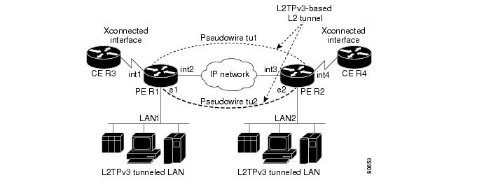
Figure 1 shows how the L2TPv3 feature is used for setting up VPNs using Layer 2 tunneling over an IP network. All traffic between two customer network sites is encapsulated in IP packets carrying L2TP data messages and sent across an IP network. The backbone routers of the IP network treat the traffic as any other IP traffic and need not know anything about the customer networks.
Figure 1 L2TPv3 Operation—Example
In Figure 1, the PE routers R1 and R2 provide L2TPv3 services. The R1 and R2 routers communicate with each other using a pseudowire over the IP backbone network through a path comprising the interfaces int1 and int2, the IP network, and interfaces int3 and int4.
In this example, the CE routers R3 and R4 communicate through a pair of xconnect Ethernet or 802.1q VLAN interfaces using an L2TPv3 session. The L2TPv3 session tu1 is a pseudowire configured between interface int1 on R1 and interface int4 on R2. Any packet arriving on interface int1 on R1 is encapsulated and sent through the pseudowire control channel (tu1) to R2. R2 decapsulates the packet and sends it on interface int4 to R4. When R4 needs to send a packet to R3, the packet follows the same path in reverse.
Note the following features regarding L2TPv3 operation:
•
•
•
Benefits of Using L2TPv3
L2TPv3 Simplifies Deployment of VPNs
L2TPv3 is an industry-standard Layer 2 tunneling protocol that ensures interoperability among vendors, increasing customer flexibility and service availability.
L2TPv3 Does Not Require MPLS
With L2TPv3 service providers need not deploy MPLS in the core IP backbone to set up VPNs using L2TPv3 over the IP backbone, resulting in operational savings and increased revenue.
L2TPv3 Supports Layer 2 Tunneling over IP for Any Payload
L2TPv3 provides enhancements to L2TP to support Layer 2 tunneling of any payload over an IP core network. L2TPv3 defines the base L2TP protocol as being separate from the Layer 2 payload that is tunneled.
L2TPv3 Header Description
The migration from UTI to L2TPv3 also requires the standardization of the UTI header. As a result, the L2TPv3 header has the new format shown in Figure 2.
Figure 2 L2TPv3 Header Format
Each L2TPv3 packet contains an L2TPv3 header that includes a unique session ID representing one session and a variable cookie length. The L2TPv3 session ID and the Tunnel Cookie field length are assigned through the CLI. See the section " How to Configure Layer 2 Tunnel Protocol Version 3" for more information on the CLI commands for L2TPv3.
Session ID
The L2TPv3 session ID is similar to the UTI session ID, and identifies the session context on the decapsulating system. For dynamic sessions, the value of the session ID is selected to optimize the context identification efficiency of the decapsulating system. A decapsulation implementation may therefore elect to support a smaller session ID bit field. In this L2TPv3 implementation, an upper value for the L2TPv3 session ID was set at 023. The L2TPv3 session ID value 0 is reserved for use by the protocol. For static sessions, the session ID is manually configured.
Note
Session Cookie
The L2TPv3 header contains a control channel cookie field that is similar to the UTI control channel key field. The control channel cookie field, however, has a variable length of 0, 4, or 8 bytes according to the cookie length supported by a given platform for packet decapsulation. The control channel cookie length can be manually configured for static sessions, or dynamically determined for dynamic sessions.
The variable cookie length does not present a problem when the same platform is at both ends of an L2TPv3 control channel. However, when different platforms interoperate across an L2TPv3 control channel, both platforms need to encapsulate packets with a 4-byte cookie length.
Pseudowire Control Encapsulation
The L2TPv3 pseudowire control encapsulation consists of 32 bits (4 bytes) and contains information used to sequence L2TP packets (see the section " Sequencing") and to distinguish AAL5 data and OAM cells for AAL5 SDU mode over L2TPv3. For the purposes of sequencing, only the first bit and bits 8 to 31 are relevant.
Bit 1 indicates whether the Sequence Number field, bits 8 to 31, contains a valid sequence number and is to be updated.
L2TPv3 Features
L2TPv3 provides xconnect support for Ethernet, 802.1q (VLAN), Frame Relay, HDLC, and PPP, using the sessions described in the following sections:
•
•
L2TPv3 also includes support for the features described in the following sections:
•
•
•
•
•
•
Static L2TPv3 Sessions
Typically, the L2TP control plane is responsible for negotiating session parameters (such as the session ID or the cookie) to set up the session. However, some IP networks require sessions to be configured so that no signaling is required for session establishment. Therefore, you can set up static L2TPv3 sessions for a PE router by configuring fixed values for the fields in the L2TP data header. A static L2TPv3 session allows the PE to tunnel Layer 2 traffic as soon as the attachment circuit to which the session is bound comes up.
Note
When you use a static L2TPv3 session, you cannot perform circuit interworking, such as LMI, because there is no facility to exchange control messages. To perform circuit interworking, you must use a dynamic session.
Dynamic L2TPv3 Sessions
A dynamic L2TP session is established through the exchange of control messages containing attribute-value (AV) pairs. Each AV pair contains information about the nature of the Layer 2 link being forwarded: the payload type, virtual circuit (VC) ID, and so on.
Multiple L2TP sessions (one for each forwarded Layer 2 circuit) can exist between a pair of PEs, and can be maintained by a single control channel. Session IDs and cookies are dynamically generated and exchanged as part of a dynamic session setup. Information such as sequencing configuration is also exchanged. Circuit state changes (UP/DOWN) are conveyed using the set link info (SLI) message.
Sequencing
Although the correct sequence of received Layer 2 frames is guaranteed by some Layer 2 technologies (by the nature of the link, such as a serial line) or the protocol itself, forwarded Layer 2 frames may be lost, duplicated, or reordered when they traverse a network as IP packets. If the Layer 2 protocol does not provide an explicit sequencing mechanism, you can configure L2TP to sequence its data packets according to the data channel sequencing mechanism described in the L2TPv3 IETF l2tpext working group draft.
A receiver of L2TP data packets mandates sequencing through the Sequencing Required AV pair when the session is being negotiated. A sender that receives this AV pair (or that is manually configured to send sequenced packets) uses the Layer 2-specific pseudowire control encapsulation defined in L2TPv3.
You can configure L2TP to only drop out-of-order packets; you cannot configure L2TP to deliver the packets out-of-order. No reordering mechanism is available.
Cisco IOS Release 12.0(28)S and Cisco IOS Release 12.2(25)S introduced support for L2TPv3 distributed sequencing on the Cisco 7500 series routers only.
Local Switching
Local switching (from one port to another port in the same router) is supported for both static and dynamic sessions. You must configure separate IP addresses for each xconnect statement.
See the section " Configuration Examples for Layer 2 Tunnel Protocol Version 3" for an example of how to configure local port switching.
Distributed Switching
Distributed CEF switching is supported for L2TP on the Cisco 7500 series routers.
Note
L2TPv3 Layer 2 Fragmentation
Because the reassembly of fragmented packets is computationally expensive, it is desirable to avoid fragmentation issues in the service provider network. The easiest way to avoid fragmentation issues is to configure the CE routers with an path maximum transmission unit (MTU) value that is smaller than the pseudowire path MTU. However, in scenarios where this is not an option, fragmentation issues must be considered. L2TP initially supported only the following options for packet fragmentation when a packet is determined to exceed the L2TP path MTU:
•
•
•
The L2TPv3 Layer 2 Fragmentation feature introduces the ability to allow IP traffic from the CE router to be fragmented before the data enters the pseudowire, forcing the computationally expensive reassembly to occur in the CE network rather than in the service-provider network. The number of fragments that must be generated is determined based on the discovered pseudowire path MTU.
To enable the discovery of the path MTU for Layer 2 traffic, enter the ip pmtu command in a pseudowire class configuration (see "Configuring the L2TPv3 Pseudowire" section). On the PE router, the original Layer 2 header is then copied to each of the generated fragments, the L2TP/IP encapsulation is added, and the frames are forwarded through the L2TPv3 pseudowire.
Because the Don't Fragment (DF) bit in the Layer 2 encapsulation header is copied from the inner IP header to the encapsulation header, fragmentation of IP packets is performed on any packets received from the CE network that have a DF bit set to 0 and that exceed the L2TP path MTU in size. To prevent the reassembly of fragmented packets on the decapsulation router, you can enter the ip dfbit set command in the pseudowire class configuration to enable the DF bit in the outer Layer 2 header.
L2TPv3 Type of Service Marking
When Layer 2 traffic is tunneled across an IP network, information contained in the ToS bits may be transferred to the L2TP-encapsulated IP packets in one of the following ways:
•
•
See the section " Configuring a Negotiated L2TPv3 Session for Local HDLC Switching: Example" for more information about how to configure ToS information.
Keepalive
The keepalive mechanism for L2TPv3 extends only to the endpoints of the tunneling protocol. L2TP has a reliable control message delivery mechanism that serves as the basis for the keepalive mechanism. The keepalive mechanism consists of an exchange of L2TP hello messages.
If a keepalive mechanism is required, the control plane is used, although it may not be used to bring up sessions. You can manually configure sessions.
In the case of static L2TPv3 sessions, a control channel between the two L2TP peers is negotiated through the exchange of start control channel request (SCCRQ), start control channel replay (SCCRP), and start control channel connected (SCCCN) control messages. The control channel is responsible only for maintaining the keepalive mechanism through the exchange of hello messages.
The interval between hello messages is configurable per control channel. If one peer detects that the other has gone down through the keepalive mechanism, it sends a StopCCN control message and then notifies all of the pseudowires to the peer about the event. This notification results in the teardown of both manually configured and dynamic sessions.
MTU Handling
It is important that you configure an MTU appropriate for a each L2TPv3 tunneled link. The configured MTU size ensures the following:
•
•
L2TPv3 handles the MTU as follows:
•
•
•
–
–
L2TPv3 Control Message Hashing
The L2TPv3 Control Message Hashing feature introduces a new and more secure authentication system that replaces the Challenge Handshake Authentication Protocol (CHAP)-like authentication system inherited from L2TPv2, which uses the Challenge and Challenge Response AV pairs in the SCCRQ, SCCRP, and SCCCN messages.
The per-message authentication introduced by the L2TPv3 Control Message Hashing feature is designed to perform a mutual authentication between L2TP nodes, check integrity of all control messages, and guard against control message spoofing and replay attacks that would otherwise be trivial to mount against the network.
The L2TPv3 Control Message Hashing feature incorporates an optional authentication or integrity check for all control messages. The new authentication method uses a computed one-way hash over the header and body of the L2TP control message, a pre-configured shared secret that must be defined on communicating L2TP nodes, and a local and remote random value exchanged using the Nonce AV pairs. Received control messages that lack any of the required security elements are dropped.
L2TPv3 control message integrity checking is a unidirectional mechanism that does not require the configuration of a shared secret. If integrity checking is enabled on the local PE router, control messages are sent with the message digest calculated without the shared secret or Nonce AV pairs, and are verified by the remote PE router. If verification fails, the remote PE router drops the control message.
L2TPv3 Control Message Rate Limiting
The L2TPv3 Control Message Rate Limiting feature was introduced to counter the possibility of a denial-of-service attack on a router running L2TPv3. The L2TPv3 Control Message Rate Limiting feature limits the rate at which SCCRQ control packets arriving at the PE that terminates the L2TPv3 tunnel can be processed. SCCRQ control packets initiate the process of bringing up the L2TPv3 tunnel and require a large amount of the control plane resources of the PE router.
On distributed platforms, most control packet filtering occurs at the line card level, and the CPU of the RP is minimally impacted even in a worst-case denial-of-service attack scenario. This feature has minimal impact on the shared bus or switching fabric, which are typically the bottleneck of a router.
No configuration is required for the L2TPv3 Control Message Rate Limiting feature. This feature automatically runs in the background in supported releases.
L2TPv3 Digest Secret Graceful Switchover
Authentication of L2TPv3 control channel messages occurs using a password that is configured on all participating peer PE routers. In Cisco IOS releases earlier than Release 12.0(30)S, changing this password requires removing the old password from the configuration before adding the new password, causing an interruption in L2TPv3 services.The authentication password must be updated on all peer PE routers, which are often at different physical locations. It is difficult for all peer PE routers be updated with the new password simultaneously to minimize interruptions in L2TPv3 services.
Cisco IOS Release 12.0(30)S introduces the L2TPv3 Digest Secret Graceful Switchover feature. This feature allows the password used to authenticate L2TPv3 control channel messages to be changed without tearing down established L2TPv3 tunnels. This feature works only for authentication passwords configured with the L2TPv3 Control Message Hashing feature. Authentication passwords configured with the older, CHAP-like authentication system cannot be updated without tearing down L2TPv3 tunnels.
The L2TPv3 Digest Secret Graceful Switchover feature allows two control channel passwords to be configured simultaneously, so a new control channel password can be enabled without first removing the old password. Established tunnels are rapidly updated with the new password, but continues to use the old password until it is removed from the configuration. This allows authentication to continue normally with peer PE routers that have not yet been updated to use the new password. After all peer PE routers are configured with the new password, the old password can be removed from the configuration.
Manual Clearing of L2TPv3 Tunnels
Cisco IOS Release 12.0(30)S introduces the ability to clear L2TPv3 tunnels manually. In Cisco IOS releases earlier than Release 12.0(30)S, no provision was made to manually clear a specific L2TPv3 tunnel at will. This functionality provides users more control over an L2TPv3 network.
L2TPv3 Tunnel Management
New and enhanced commands have been introduced to facilitate managing xconnect configurations and diagnosing problems with xconnect configurations.
No specific configuration tasks are associated with these commands. Complete documentation for these commands is available in the " Command Reference" section of this publication.
New and enhanced commands were introduced in the following releases:
Syslog, SNMP Trap, and show Command Enhancements for L2TPv3 in Cisco IOS Release 12.0(31)S and Cisco IOS Release 12.2(27)SBC
Cisco IOS Release 12.0(31)S and Cisco IOS Release 12.2(27)SBC introduce new and enhanced commands for managing and diagnosing problems with xconnect configurations.
The following commands were introduced in Cisco IOS Release 12.0(31)S and Cisco IOS Release 12.2(27)SBC:
•
•
•
The following commands were enhanced in Cisco IOS Release 12.0(31)S and Cisco IOS Release 12.2(27)SBC:
•
•
•
Control Message Statistics and Conditional Debugging Command Enhancements in Cisco IOS Release 12.2(28)SB
Cisco IOS Release 12.2(28)SB introduces new commands and modifies existing commands for managing control message statistics and conditionally filtering xconnect debug messages.
The following commands were introduced in Cisco IOS Release 12.2(28)SB:
•
•
•
•
•
The following command was modified in Cisco IOS Release 12.2(28)SB:
•
L2TPv3 and UTI Feature Comparison
Table 4 compares L2TPv3 and UTI feature support for the Cisco 7200 and Cisco 7500 series routers.
Supported L2TPv3 Payloads
L2TPv3 supports the following Layer 2 payloads that can be included in L2TPv3 packets tunneled over the pseudowire:
•
•
•
•
•
Note
Frame Relay
L2TPv3 supports the Frame Relay functionality described in the following sections:
•
Port-to-Port Trunking
Port-to-port trunking is where two CE Frame Relay interfaces are connected as by a leased line (UTI raw mode). All traffic arriving on one interface is forwarded transparently across the pseudowire to the other interface.
For example, in Figure 1, if the two CE routers are connected by a virtual leased line, the PE routers transparently transport all packets between CE R3 and CE R4 over a pseudowire. PE R1 and PE R2 do not examine or change the DLCIs, and do not participate in the LMI protocol. The two CE routers are LMI peers. There is nothing Frame Relay-specific about this service as far as the PE routers are concerned. The CE routers should be able to use any encapsulation based on HDLC framing without needing to change the provider configuration.
DLCI-to-DLCI Switching
Frame Relay DLCI-to-DLCI switching is where individual Frame Relay DLCIs are connected to create an end-to-end Frame Relay PVC. Traffic arriving on a DLCI on one interface is forwarded across the pseudowire to another DLCI on the other interface.
For example, in Figure 1, CE R3 and PE R1 are Frame Relay LMI peers; CE R4 and PE R2 are also LMI peers. You can use a different type of LMI between CE R3 and PE R1 compared to what you use between CE R4 and PE R2.
The CE devices may be a Frame Relay switch or end-user device. Each Frame Relay PVC is composed of multiple segments. The DLCI value is local to each segment and is changed as traffic is switched from segment to segment. Note that, in Figure 1, two Frame Relay PVC segments are connected by a pseudowire. Frame Relay header flags (FECN, BECN, C/R, DE) are preserved across the pseudowire.
PVC Status Signaling
PVC status signaling is propagated toward Frame Relay end users by the LMI protocol. You can configure the LMI to operate in any of the following modes:
•
•
•
L2TPv3 supports all three modes.
The PVC status should be reported as ACTIVE only if the PVC is available from the reporting device to the Frame Relay end-user device. All interfaces, line protocols, and pseudowires must be operational between the reporting device and the Frame Relay end-user device.
Note that any keepalive functions on the session are independent of Frame Relay, but any state changes that are detected are fed into the PVC status reporting. For example, the L2TP control channel uses hello packets as a keepalive function. If the L2TPv3 keepalive fails, all L2TPv3 sessions are torn down. Loss of the session is notified to Frame Relay, which can then report PVCs INACTIVE to the CE devices.
For example, in Figure 1, CE R3 reports ACTIVE to PE R1 only if the PVC is available within CE R3. When CE R3 is a switch, it reports all the way to the user device in the customer network.
PE R1 reports ACTIVE to CE R3 only if the PVC is available within PE R1 and all the way to the end-user device (through PE R2 and CE R3) in the other customer VPN site.
The ACTIVE state is propagated hop-by-hop, independently in each direction, from one end of the Frame Relay network to the other end.
Sequencing
Frame Relay provides an ordered service in which packets sent to the Frame Relay network by one end-user device are delivered in order to the other end-user device. When switching is occurring over the pseudowire, packet ordering must be able to be preserved with a very high probability to closely emulate a traditional Frame Relay service. If the CE router is not using a protocol that can detect misordering itself, configuring sequence number processing may be important. For example, if the Layer 3 protocol is IP and Frame Relay is therefore used only for encapsulation, sequencing is not required. To detect misordering, you can configure sequence number processing separately for transmission or reception. For more information about how to configure sequencing, see the section " Configuring a Negotiated L2TPv3 Session for Local HDLC Switching: Example."
ToS Marking
The ToS bytes in the IP header can be statically configured or reflected from the internal IP header. The Frame Relay discard eligible (DE) bit does not influence the ToS bytes.
CIR Guarantees
To provide committed information rate (CIR) guarantees, you can configure a queueing policy that provides bandwidth to each DLCI to the interface facing the customer network on the egress PE.
Note
Binding L2TPv3 Sessions to Multilink Frame Relay Interfaces
The configuration of an L2TPv3 session on a Multilink Frame Relay (MLFR) bundle interface is supported only on Cisco 12000 series 2-port channelized OC-3/STM-1 (DS1/E1) and 6-port channelized T3 (T1) line cards.
The Multilink Frame Relay feature introduces functionality based on the Frame Relay Forum Multilink Frame Relay UNI/NNI Implementation Agreement (FRF.16). This feature provides a cost-effective way to increase bandwidth for particular applications by enabling multiple serial links to be aggregated into a single bundle of bandwidth.
For an example of how to configure L2TPv3 tunneling on a multilink Frame Relay bundle interface, see Configuring MLFR for L2TPv3 on the Cisco 12000 Series: Example.
For information about how configure and use the MLFR feature, refer to the Multilink Frame Relay (FRF.16) publication.
Ethernet
An Ethernet frame arriving at a PE router is simply encapsulated in its entirety with an L2TP data header. At the other end, a received L2TP data packet is stripped of its L2TP data header. The payload, an Ethernet frame, is then forwarded to the appropriate attachment circuit.
Because the L2TPv3 tunneling protocol serves essentially as a bridge, it need not examine any part of an Ethernet frame. Any Ethernet frame received on an interface is tunneled, and any L2TP-tunneled Ethernet frame is forwarded out the interface.
Note
802.1q (VLAN)
L2TPv3 supports VLAN membership in the following ways:
•
•
In L2TPv3, Ethernet xconnect supports port-based VLAN membership and the reception of tagged Ethernet frames. A tagged Ethernet frame contains a tag header (defined in 802.1Q), which is 4 bytes long and consists of a 2-byte tag protocol identifier (TPID) field and a 2-byte tag control information (TCI) field. The TPID indicates that a TCI follows. The TCI is further broken down into the following three fields:
•
•
•
For L2TPv3, an Ethernet subinterface configured to support VLAN switching may be bound to an xconnect service so that all Ethernet traffic, tagged with a VID specified on the subinterface, is tunneled to another PE. The VLAN Ethernet frames are forwarded in their entirety. The receiving PE may rewrite the VID of the tunneled traffic to another value before forwarding the traffic onto an attachment circuit.
To successfully rewrite VLANs, it may be necessary to disable the Spanning Tree Protocol (STP). This can be done on a per-VLAN basis by using the no spanning-tree vlan command.
Note
HDLC
L2TPv3 encapsulates an HDLC frame arriving at a PE in its entirety (including the Address, Control, and Protocol fields, but not the Flag fields and the frame check sequence) with an L2TP data header.
PPP
PEs that support L2TPv3 forward PPP traffic using a "transparent pass-through" model, in which the PEs play no role in the negotiation and maintenance of the PPP link. L2TPv3 encapsulates a PPP frame arriving at a PE in its entirety (including the HDLC Address and Control fields) with an L2TP data header.
ATM
L2TPv3 can connect two isolated ATM clouds over a packet-switched network (PSN) while maintaining an end-to-end ATM Service Level Agreement (SLA). The ATM Single Cell Relay features forward one ATM cell per packet. The ATM Cell Packing over L2TPv3 features allows multiple ATM frames to be packed into a single L2TPv3 data packet. All packets are transparently forwarded over the L2TPv3 pseudowire.
Note
Table 5 shows the releases that introduced support for the ATM cell relay features.
ATM Single Cell Relay VC Mode over L2TPv3
The ATM Single Cell Relay VC mode over L2TPv3 feature maps one VC to a single L2TPv3 session. All ATM cells arriving at an ATM interface with the specified VPI and VCI are encapsulated into a single L2TP packet. Each ATM cell will have a 4-byte ATM cell header without Header Error Control Checksum (HEC) and a 48-byte ATM cell payload.
The ATM Single Cell Relay VC mode feature can be used to carry any type of AAL traffic over the pseudowire. It will not distinguish OAM cells from User data cells. In this mode, Performance and Security OAM cells are also transported over the pseudowire.
ATM VP Mode Single Cell Relay over L2TPv3
The ATM VP Mode Single Cell Relay over L2TPv3 feature allows cells coming into a predefined PVP on the ATM interface to be transported over an L2TPv3 pseudowire to a predefined PVP on the egress ATM interface. A single ATM cell is encapsulated into each L2TPv3 data packet.
ATM Port Mode Cell Relay over L2TPv3
The ATM Port Mode Cell Relay over L2TPv3 feature packs ATM cells arriving at an ingress ATM interface into L2TPv3 data packets and transports them to the egress ATM interface. A single ATM cell is encapsulated into each L2TPv3 data packet.
ATM Cell Packing over L2TPv3
The ATM Cell Packing over L2TPv3 feature enhances throughput and uses bandwidth more efficiently than the ATM cell relay features. Instead of a single ATM cell being packed into each L2TPv3 data packet, multiple ATM cells can be packed into a single L2TPv3 data packet. ATM cell packing is supported for Port mode, VP mode, and VC mode. Cell packing must be configured on the PE devices. No configuration is required on the CE devices.
ATM AAL5 over L2TPv3
The ATM AAL5 over L2TPv3 feature maps the AAL5 payload of an AAL5 PVC to a single L2TPv3 session. This service will transport OAM and RM cells, but does not attempt to maintain the relative order of these cells with respect to the cells that comprise the AAL5 common part convergence sublayer protocol data unit (CPCS-PDU). OAM cells that arrive during the reassembly of a single AAL5 CPCS-PDU are sent immediately over the pseudowire, followed by the AAL5 payload without the AAL5 pad and trailer bytes.
VC Class Provisioning for L2TPv3
Beginning in Cisco IOS Release 12.0(30)S, ATM AAL5 encapsulation over L2TPv3 can be configured in VC class configuration mode in addition to ATM VC configuration mode. The ability to configure ATM encapsulation parameters in VC class configuration mode provides greater control and flexibility for AAL5 encapsulation configurations.
OAM Transparent Mode
In OAM transparent mode, the PEs will pass the following OAM cells transparently across the pseudowire:
•
•
Note
VPI or VPI/VCI rewrite is not supported for any ATM transport mode. Both pairs of PE to CE peer routers must be configured with matching VPI and VCI values except in OAM local emulation mode. For example, if PE1 and CE1 are connected by PVC 10/100, PE2 and CE2 should also be connected by PVC 10/100.
OAM Local Emulation Mode
In OAM Local Emulation mode, OAM cells are not passed through the pseudowire. All F5 OAM cells are terminated and handled locally. On the L2TPv3-based pseudowire, the CE device sends an SLI message across the pseudowire to notify the peer PE node about the defect, rather than tearing down the session. The defect can occur at any point in the link between the local CE and the PE. OAM management can also be enabled on the PE node using existing OAM management configurations.
IPv6 Protocol Demultiplexing
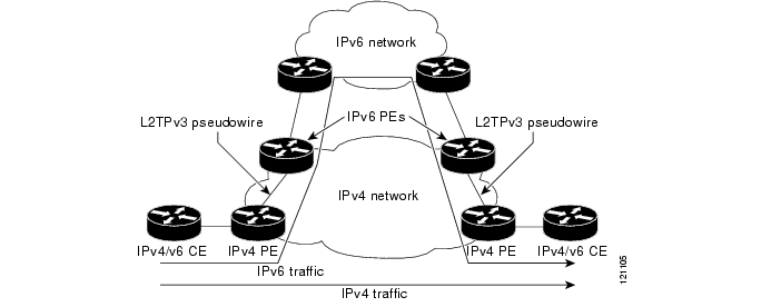
Upgrading a service provider network to support IPv6 is a long and expensive process. As an interim solution, the Protocol Demultiplexing for L2TPv3 feature introduces the ability to provide native IPv6 support by setting up a specialized IPv6 network and offloading IPv6 traffic from the IPv4 network. IPv6 traffic is transparently tunneled to the IPv6 network using L2TPv3 pseudowires without affecting the configuration of the CE routers. IPv4 traffic is routed as usual within the IPv4 network, maintaining the existing performance and reliability of the IPv4 network.
Figure 3 shows a network deployment that offloads IPv6 traffic from the IPv4 network to a specialized IPv6 network. The PE routers demultiplex the IPv6 traffic from the IPv4 traffic. IPv6 traffic is routed to the IPv6 network over an L2TPv3 pseudowire, while IPv4 traffic is routed normally. The IPv4 PE routers must be configured to demultiplex incoming IPv6 traffic from IPv4 traffic. The PE routers facing the IPv6 network do not require demultiplexing configuration.
Figure 3 Protocol Demultiplexing of IPv6 Traffic from IPv4 Traffic
IPv6 protocol demultiplexing is supported only for Ethernet and Frame Relay traffic beginning in Cisco IOS Release 12.0(29)S and Cisco IOS Release 12.2(27)SBC. Protocol demultiplexing requires supporting the combination of an IP address and an xconnect command configuration on the IPv4 PE interface. This combination of configurations is not allowed without enabling protocol demultiplexing, with the exception of switched Frame Relay PVCs. If no IP address is configured, the protocol demultiplexing configuration is rejected. If an IP address is configured, the xconnect command configuration is rejected unless protocol demultiplexing is enabled in xconnect configuration mode before exiting that mode. If an IP address is configured with an xconnect command configuration and protocol demultiplexing enabled, the IP address cannot be removed. To change or remove the configured IP address, the xconnect command configuration must first be disabled.
Table 6 shows the valid combinations of configurations.
Table 6 Valid Configuration Scenarios
Routing
Yes
No
—
L2VPN
No
Yes
No
IPv6 Protocol Demultiplexing
Yes
Yes
Yes
How to Configure Layer 2 Tunnel Protocol Version 3
This section contains the following procedures:
•
•
•
•
•
•
•
•
•
•
•
•
Configuring L2TP Control Channel Parameters
The L2TP class configuration procedure creates a template of L2TP control channel parameters that can be inherited by different pseudowire classes. L2TP control channel parameters are used in control channel authentication, keepalive messages, and control channel negotiation. In an L2TPv3 session, the same L2TP class must be specified in the pseudowire configured on the PE router at each end of the control channel. Configuring L2TP control channel parameters is optional. However, the L2TP class must be configured before it is with associated a pseudowire class (see the section " Configuring the L2TPv3 Pseudowire").
The three main groups of L2TP control channel parameters that you can configure in an L2TP class are described in the following sections:
•
•
•
After you enter L2TP class configuration mode, you can configure L2TP control channel parameters in any order. If you have multiple authentication requirements you can configure multiple sets of L2TP class control channel parameters with different L2TP class names. However, only one set of L2TP class control channel parameters can be applied to a connection between any pair of IP addresses.
Configuring L2TP Control Channel Timing Parameters
The following L2TP control channel timing parameters can be configured in L2TP class configuration mode:
•
•
•
This task configures a set of timing control channel parameters in an L2TP class. All of the timing control channel parameter configurations are optional and may be configured in any order. If these parameters are not configured, the default values are applied.
SUMMARY STEPS
1.
2.
3.
4.
5.
6.
DETAILED STEPS
Configuring L2TPv3 Control Channel Authentication Parameters
Two methods of control channel message authentication are available beginning in Cisco IOS Release 12.0(29)S and Cisco IOS Release 12.2(27)SBC. The L2TPv3 Control Message Hashing feature introduces a more robust authentication method than the older CHAP-style L2TP control channel method of authentication. You may choose to enable both methods of authentication to ensure interoperability with peers that support only one of these methods of authentication, but this configuration will yield control of which authentication method is used to the peer PE router. Enabling both methods of authentication should be considered an interim solution to solve backward-compatibility issues during software upgrades.
The principal difference between the L2TPv3 Control Message Hashing feature and CHAP-style L2TP control channel authentication is that, instead of computing the hash over selected contents of a received control message, the L2TPv3 Control Message Hashing feature uses the entire message in the hash. In addition, instead of including the hash digest in only the SCCRP and SCCCN messages, it includes it in all messages.
Support for L2TP control channel authentication is maintained for backward compatibility. Either or both authentication methods can be enabled to allow interoperability with peers supporting only one of the authentication methods.
Table 7 shows a compatibility matrix for the different L2TPv3 authentication methods. PE1 is running Cisco IOS 12.0(29)S, and the different possible authentication configurations for PE1 are shown in the first column. Each remaining column represents PE2 running software with different available authentication options, and the intersections indicate the different compatible configuration options for PE2. If any PE1/PE2 authentication configuration poses ambiguity on which method of authentication is used, the winning authentication method is indicated in bold. If both the old and new authentication methods are enabled on PE1 and PE2, both types of authentication occur.
Table 7 Compatibility Matrix for L2TPv3 Authentication Methods
None
None
None
New integrity check
None
New integrity check
Old authentication
Old authentication
—
Old authentication
Old authentication and new authentication
Old authentication and new integrity check
New authentication
—
New authentication
New authentication
Old authentication and new authentication
New integrity check
None
None
New integrity check
None
New integrity check
Old and new authentication
Old authentication
New authentication
Old authentication
New authentication
Old and new authentication
Old authentication and new integrity check
Old authentication and new integrity check
Old authentication
—
Old authentication
Old authentication and new authentication
Old authentication and new integrity check
1 Any PE software that supports only the old CHAP-like authentication system.
2 Any PE software that supports only the new message digest authentication and integrity checking authentication system, but does not understand the old CHAP-like authentication system. This type of software may be implemented by other vendors based on the latest L2TPv3 draft.
3 Any PE software that supports both the old CHAP-like authentication and the new message digest authentication and integrity checking authentication system, such as Cisco IOS Release 12.0(29)S or Cisco IOS Release 12.2(27)SBC.
Perform one or both of the following tasks to configure authentication parameters for the L2TPv3 control channel messages:
•
•
If you choose to configure authentication using the L2TPv3 Control Message Hashing feature, you may perform the following optional task:
•
Configuring Authentication for the L2TP Control Channel
The L2TP control channel method of authentication is the older, CHAP-like authentication system inherited from L2TPv2.
The following L2TP control channel authentication parameters can be configured in L2TP class configuration mode:
•
•
•
This task configures a set of authentication control channel parameters in an L2TP class. All of the authentication control channel parameter configurations are optional and may be configured in any order. If these parameters are not configured, the default values are applied.
SUMMARY STEPS
1.
2.
3.
4.
5.
6.
DETAILED STEPS
Configuring L2TPv3 Control Message Hashing
The L2TPv3 Control Message Hashing feature introduced in Cisco IOS Release 12.0(29)S and Cisco IOS Release 12.2(27)SBC is a new authentication system that is more secure than the CHAP-style L2TP control channel method of authentication. L2TPv3 Control Message Hashing incorporates an optional authentication or integrity check for all control messages. This per-message authentication is designed to guard against control message spoofing and replay attacks that would otherwise be trivial to mount against the network.
Enabling the L2TPv3Control Message Hashing feature will impact performance during control channel and session establishment because additional digest calculation of the full message content is required for each sent and received control message. This is an expected trade-off for the additional security afforded by this feature. In addition, network congestion may occur if the receive window size is too small. If the L2TPv3 Control Message Hashing feature is enabled, message digest validation must be enabled. Message digest validation deactivates the data path received sequence number update and restricts the minimum local receive window size to 35.
You may choose to configure control channel authentication or control message integrity checking. Control channel authentication requires participation by both peers, and a shared secret must be configured on both routers. Control message integrity check is unidirectional, and requires configuration on only one of the peers.
This task configures L2TPv3 Control Message Hashing feature for an L2TP class.
SUMMARY STEPS
1.
2.
3.
4.
5.
6.
DETAILED STEPS
Step 1
enable
Example:Router> enable
Enables privileged EXEC mode.
•
Step 2
configure terminal
Example:Router# configure terminal
Enters global configuration mode.
Step 3
l2tp-class [l2tp-class-name]
Example:Router(config)# l2tp-class class1
Specifies the L2TP class name and enters L2TP class configuration mode.
•
Step 4
digest [secret [0 | 7] password] [hash {md5 | sha}]
Example:Router(config-l2tp-class)# digest secret cisco hash sha
(Optional) Enables L2TPv3 control channel authentication or integrity checking.
•
Note
•
–
–
•
•
–
–
The default hash function is md5.
Step 5
digest check
Example:Router(config-l2tp-class)# digest check
(Optional) Enables the validation of the message digest in received control messages.
•
Note
Step 6
hidden
Example:Router(config-l2tp-class)#
hidden(Optional) Enables AV pair hiding when sending control messages to an L2TPv3 peer.
•
•
•
Note
Configuring L2TPv3 Digest Secret Graceful Switchover
L2TPv3 control channel authentication occurs using a password that is configured on all participating peer PE routers. The L2TPv3 Digest Secret Graceful Switchover feature allows a transition from an old control channel authentication password to a new control channel authentication password without disrupting established L2TPv3 tunnels. This feature was introduced in Cisco IOS Release 12.0(30)S.
During the period when both a new and an old password are configured, authentication will occur only with the new password if the attempt to authenticate using the old password fails.
Perform this task to make the transition from an old L2TPv3 control channel authentication password to a new L2TPv3 control channel authentication password without disrupting established L2TPv3 tunnels.
Prerequisites
Before performing this task, you must enable control channel authentication as documented in the task " Configuring L2TPv3 Control Message Hashing."
Restrictions
This task is not compatible with authentication passwords configured with the older, CHAP-like control channel authentication system.
SUMMARY STEPS
1.
2.
3.
4.
5.
6.
7.
8.
9.
10.
11.
DETAILED STEPS
Step 1
enable
Example:Router> enable
Enables privileged EXEC mode.
•
Step 2
configure terminal
Example:Router# configure terminal
Enters global configuration mode.
Step 3
l2tp-class [l2tp-class-name]
Example:Router(config)# l2tp-class class1
Specifies the L2TP class name and enters L2TP class configuration mode.
•
Step 4
digest [secret [0 | 7] password] [hash {md5 | sha}]
Example:Router(config-l2tp-class)# digest secret cisco2 hash sha
Configures a new password to be used in L2TPv3 control channel authentication.
•
Note
Step 5
end
Example:Router(config-l2tp-class)# end
Ends your configuration session by exiting to privileged EXEC mode.
Step 6
show l2tun tunnel all
Example:Router# show l2tun tunnel all
(Optional) Displays the current state of Layer 2 tunnels and information about configured tunnels, including local and remote Layer 2 Tunneling Protocol (L2TP) hostnames, aggregate packet counts, and control channel information.
•
Note
Step 7
configure terminal
Example:Router# configure terminal
Enters global configuration mode.
Step 8
l2tp-class [l2tp-class-name]
Example:Router(config)# l2tp-class class1
Specifies the L2TP class name and enters L2TP class configuration mode.
•
Step 9
no digest [secret [0 | 7] password] [hash {md5 | sha}]
Example:Router(config-l2tp-class)# no digest secret cisco hash sha
Removes the old password used in L2TPv3 control channel authentication.
Note
Step 10
end
Example:Router(config-l2tp-class)# end
Ends your configuration session by exiting to privileged EXEC mode.
Step 11
show l2tun tunnel all
Example:Router# show l2tun tunnel all
(Optional) Displays the current state of Layer 2 tunnels and information about configured tunnels, including local and remote Layer 2 Tunneling Protocol (L2TP) hostnames, aggregate packet counts, and control channel information.
•
Note
Configuring L2TP Control Channel Maintenance Parameters
The L2TP hello packet keepalive interval control channel maintenance parameter can be configured in L2TP class configuration mode.
This task configures the interval used for hello messages in an L2TP class. This control channel parameter configuration is optional. If this parameter is not configured, the default value is applied.
SUMMARY STEPS
1.
2.
3.
4.
DETAILED STEPS
Configuring the L2TPv3 Pseudowire
The pseudowire class configuration procedure creates a configuration template for the pseudowire. Use this template, or class, to configure session-level parameters for L2TPv3 sessions that are used to transport attachment circuit traffic over the pseudowire.
The pseudowire configuration specifies the characteristics of the L2TPv3 signaling mechanism, including the data encapsulation type, the control protocol, sequencing, fragmentation, payload-specific options, and IP properties. The setting that determines if signaling is used to set up the pseudowire is also included.
For simple L2TPv3 signaling configurations on most platforms, pseudowire class configuration is optional. However, specifying a source IP address to configure a loopback interface is highly recommended. If you do not configure a loopback interface, the router will choose the best available local address, which could be any IP address configured on a core-facing interface. This configuration could prevent a control channel from being established. On the Cisco 12000 series Internet routers, specifying a source IP address is mandatory, and you should configure a loopback interface that is dedicated for the use of L2TPv3 sessions exclusively. If you do not configure other pseudowire class configuration commands, the default values are used.
Once you specify the encapsulation l2tpv3 command, you cannot remove it using the no encapsulation l2tpv3 command. Nor can you change the command's setting using the encapsulation mpls command. Those methods result in the following error message:
Encapsulation changes are not allowed on an existing pw-class.To remove the command, you must delete the pseudowire with the no pseudowire-class command. To change the type of encapsulation, remove the pseudowire with the no pseudowire-class command and re-establish the pseudowire and specify the new encapsulation type.
SUMMARY STEPS
1.
2.
3.
4.
5.
6.
7.
8.
9.
10.
11.
12.
DETAILED STEPS
Step 1
enable
Example:Router> enable
Enables privileged EXEC mode.
•
Step 2
configure terminal
Example:Router# configure terminal
Enters global configuration mode.
Step 3
pseudowire-class [pw-class-name]
Example:Router(config)# pseudowire-class etherpw
Enters pseudowire class configuration mode and optionally specifies the name of the L2TP pseudowire class.
Step 4
encapsulation l2tpv3
Example:Router(config-pw)# encapsulation l2tpv3
Specifies that L2TPv3 is used as the data encapsulation method to tunnel IP traffic.
Step 5
protocol {l2tpv3 | none}[l2tp-class-name]
Example:Router(config-pw)#
protocol l2tpv3 class1(Optional) Specifies the L2TPv3 signaling protocol to be used to manage the pseudowires created with the control channel parameters in the specified L2TP class (see the section " Configuring L2TP Control Channel Parameters").
•
•
Step 6
ip local interface interface-name
Example:Router(config-pw)#
ip local interface e0/0Specifies the PE router interface whose IP address is to be used as the source IP address for sending tunneled packets.
•
Note
Step 7
ip pmtu
Example:Router(config-pw)#
ip pmtu(Optional) Enables the discovery of the path MTU for tunneled traffic.
•
Note
•
Note
Step 8
ip tos {value value | reflect}
Example:Router(config-pw)# ip tos reflect
(Optional) Configures the value of the ToS byte in IP headers of tunneled packets, or reflects the ToS byte value from the inner IP header.
•
Step 9
ip dfbit set
Example:Router(config-pw)# ip dfbit set
(Optional) Configures the value of the DF bit in the outer headers of tunneled packets.
•
Note
Step 10
ip ttl value
Example:Router(config-pw)# ip ttl 100
(Optional) Configures the value of the time to live (TTL) byte in the IP headers of tunneled packets.
•
Step 11
ip protocol {l2tp | uti | protocol-number}
Example:Router(config-pw)# ip protocol uti
(Optional) Configures the IP protocol to be used for tunneling packets.
•
Step 12
sequencing {transmit | receive | both}
Example:Router(config-pw)# sequencing both
(Optional) Specifies the direction in which sequencing of data packets in a pseudowire is enabled:
•
•
•
Configuring the Xconnect Attachment Circuit
This configuration procedure binds an Ethernet, 802.1q VLAN, or Frame Relay attachment circuit to an L2TPv3 pseudowire for xconnect service. The virtual circuit identifier that you configure creates the binding between a pseudowire configured on a PE router and an attachment circuit in a CE device. The virtual circuit identifier configured on the PE router at one end of the L2TPv3 control channel must also be configured on the peer PE router at the other end.
SUMMARY STEPS
1.
2.
3.
4.
DETAILED STEPS
Step 1
enable
Example:Router> enable
Enables privileged EXEC mode.
•
Step 2
configure terminal
Example:Router# configure terminal
Enters global configuration mode.
Step 3
interface type slot/port
Example:Router(config)# interface ethernet 0/0
Specifies the interface by type (for example, Ethernet) and slot and port number, and enters interface configuration mode.
Step 4
xconnect peer-ip-address vcid pseudowire-parameters [sequencing {transmit | receive | both}]
Example:Router(config-if)# xconnect 10.0.3.201 123 pw-class vlan-xconnect
Specifies the IP address of the peer PE router and the 32-bit virtual circuit identifier shared between the PE at each end of the control channel.
•
•
–
•
•
•
–
•
•
Note
Note
•
Manually Configuring L2TPv3 Session Parameters
When you bind an attachment circuit to an L2TPv3 pseudowire for xconnect service using the xconnect l2tpv3 manual command (see the section " Configuring the Xconnect Attachment Circuit") because you do not want signaling, you must then configure L2TP-specific parameters to complete the L2TPv3 control channel configuration.
SUMMARY STEPS
1.
2.
3.
4.
5.
6.
7.
8.
DETAILED STEPS
Step 1
enable
Example:Router> enable
Enables privileged EXEC mode.
•
Step 2
configure terminal
Example:Router# configure terminal
Enters global configuration mode.
Step 3
interface type slot/port
Example:Router(config)# interface ethernet 0/0
Specifies the interface by type (for example, Ethernet) and slot and port number, and enters interface configuration mode.
Step 4
xconnect peer-ip-address vc-id encapsulation l2tpv3 manual pw-class pw-class-name
Example:Router(config-if)# xconnect 10.0.3.201 123 encapsulation l2tpv3 manual pw-class vlan-xconnect
Specifies the IP address of the peer PE router and the 32-bit virtual circuit identifier shared between the PE at each end of the control channel.
•
•
•
Step 5
l2tp id local-session-id remote-session-id
Example:Router(config-if-xconn)# l2tp id 222 111
Configures the identifiers for the local L2TPv3 session and for the remote L2TPv3 session on the peer PE router.
•
Step 6
l2tp cookie local size low-value [high-value]
Example:Router(config-if-xconn)#
l2tp cookie local 4 54321(Optional) Specifies the value that the peer PE must include in the cookie field of incoming (received) L2TP packets.
•
•
Step 7
l2tp cookie remote size low-value [high-value]
Example:Router(config-if-xconn)#
l2tp cookie remote 4 12345(Optional) Specifies the value that the router includes in the cookie field of outgoing (sent) L2TP packets.
•
•
Step 8
l2tp hello l2tp-class-name
Example:Router(config-if-xconn)#
l2tp hello l2tp-defaults(Optional) Specifies the L2TP class name to use (see the section " Configuring L2TP Control Channel Parameters") for control channel configuration parameters, including the interval to use between hello keepalive messages.
Note
Configuring the Xconnect Attachment Circuit for ATM VP Mode Single Cell Relay over L2TPv3
The ATM VP Mode Single Cell Relay over L2TPv3 feature allows cells coming into a predefined PVP on the ATM interface to be transported over an L2TPv3 pseudowire to a predefined PVP on the egress ATM interface. This task binds a PVP to an L2TPv3 pseudowire for xconnect service.
SUMMARY STEPS
1.
2.
3.
4.
5.
DETAILED STEPS
Configuring the Xconnect Attachment Circuit for ATM Single Cell Relay VC Mode over L2TPv3
The ATM Single Cell Relay VC Mode over L2TPv3 feature maps one VCC to a single L2TPv3 session. All ATM cells arriving at an ATM interface with the specified VPI and VCI are encapsulated into a single L2TP packet.
The ATM Single Cell Relay VC mode feature can be used to carry any type of AAL traffic over the pseudowire. It will not distinguish OAM cells from User data cells. In this mode, PM and Security OAM cells are also transported over the pseudowire.
Perform this task to enable the ATM Single Cell Relay VC Mode over L2TPv3 feature.
SUMMARY STEPS
1.
2.
3.
4.
5.
6.
DETAILED STEPS
Step 1
enable
Example:Router> enable
Enables privileged EXEC mode.
•
Step 2
configure terminal
Example:Router# configure terminal
Enters global configuration mode.
Step 3
interface type slot/port
Example:Router(config)# interface ATM 4/1
Specifies the interface by type, slot, and port number, and enters interface configuration mode.
Step 4
pvc [name] vpi/vci l2transport
Example:Router(config-if)# pvc 5/500 l2transport
Creates or assigns a name to an ATM PVC, specifies the encapsulation type on an ATM PVC, and enters ATM VC configuration mode.
•
Step 5
encapsulation aal0
Example:Router(config-atm-vc)# encapsulation aal0
Specifies ATM AAL0 encapsulation for the PVC.
Step 6
xconnect peer-ip-address vcid pw-class pw-class-name
Example:Router(config-atm-vc)# xconnect 10.0.3.201 888 pw-class atm-xconnect
Specifies the IP address of the peer PE router and the 32-bit VCI shared between the PE at each end of the control channel.
•
•
Note
Configuring the Xconnect Attachment Circuit for ATM Port Mode Cell Relay over L2TPv3
The ATM Port Mode Cell Relay feature packs ATM cells arriving at an ingress ATM interface into L2TPv3 data packets and transports them to the egress ATM interface. A single ATM cell is encapsulated into each L2TPv3 data packet.
Perform this task to enable the ATM Port Mode Cell Relay over L2TPv3 feature.
SUMMARY STEPS
1.
2.
3.
4.
DETAILED STEPS
Step 1
enable
Example:Router> enable
Enables privileged EXEC mode.
•
Step 2
configure terminal
Example:Router# configure terminal
Enters global configuration mode.
Step 3
interface type slot/port
Example:Router(config)# interface ATM 4/1
Specifies the interface by type, slot, and port number, and enters interface configuration mode.
Step 4
xconnect peer-ip-address vcid pw-class pw-class-name
Example:Router(config-if)# xconnect 10.0.3.201 888 pw-class atm-xconnect
Specifies the IP address of the peer PE router and the 32-bit VCI shared between the PE at each end of the control channel.
•
•
Note
Configuring the Xconnect Attachment Circuit for ATM Cell Packing over L2TPv3
The ATM Cell Packing over L2TPv3 feature allows multiple ATM frames to be packed into a single L2TPv3 data packet. ATM cell packing can be configured for Port mode, VP mode, and VC mode. Perform one of the following tasks to configure the ATM Cell Packing over L2TPv3 feature:
•
•
•
Configuring Port Mode ATM Cell Packing over L2TPv3
Perform this task to configure port mode ATM cell packing over L2TPv3.
SUMMARY STEPS
1.
2.
3.
4.
5.
6.
DETAILED STEPS
Configuring VP Mode ATM Cell Packing over L2TPv3
Perform this task to configure VP mode ATM cell packing over L2TPv3.
SUMMARY STEPS
1.
2.
3.
4.
5.
6.
7.
DETAILED STEPS
Configuring VC Mode ATM Cell Packing over L2TPv3
Perform this task to configure VC mode ATM cell packing over L2TPv3.
SUMMARY STEPS
1.
2.
3.
4.
5.
6.
7.
8.
DETAILED STEPS
Configuring the Xconnect Attachment Circuit for ATM AAL5 SDU Mode over L2TPv3
The ATM AAL5 SDU Mode feature maps the AAL5 payload of an AAL5 PVC to a single L2TPv3 session. This service will transport OAM and RM cells, but does not attempt to maintain the relative order of these cells with respect to the cells that comprise the AAL5 CPCS-PDU. OAM cells that arrive during the reassembly of a single AAL5 CPCS-PDU are sent immediately over the pseudowire, followed by the AAL5 SDU payload.
Beginning in Cisco IOS Release 12.0(30)S, you may choose to configure the ATM AAL5 SDU Mode feature in ATM VC configuration mode or in VC class configuration mode.
To enable the ATM AAL5 SDU Mode feature, perform one of the following tasks:
•
•
Configuring ATM AAL5 SDU Mode over L2TPv3 in ATM VC Configuration Mode
Perform this task to bind a PVC to an L2TPv3 pseudowire for ATM AAL5 SDU mode xconnect service.
SUMMARY STEPS
1.
2.
3.
4.
5.
6.
DETAILED STEPS
Step 1
enable
Example:Router> enable
Enables privileged EXEC mode.
•
Step 2
configure terminal
Example:Router# configure terminal
Enters global configuration mode.
Step 3
interface type slot/port
Example:Router(config)# interface ATM 4/1
Specifies the interface by type, slot, and port number, and enters interface configuration mode.
Step 4
pvc [name] vpi/vci [l2transport]
Example:Router(config-if)# pvc 5/500 l2transport
Creates or assigns a name to an ATM permanent virtual circuit (PVC), specifies the encapsulation type on an ATM PVC, and enters ATM VC configuration mode.
•
Step 5
encapsulation aal5
Example:Router(config-atm-vc)# encapsulation aal5
Specifies ATM AAL5 encapsulation for the PVC.
Step 6
xconnect peer-ip-address vcid pw-class pw-class-name
Example:Router(config-atm-vc)# xconnect 10.0.3.201 888 pw-class atm-xconnect
Specifies the IP address of the peer PE router and the 32-bit VCI shared between the PE at each end of the control channel.
•
•
Note
Configuring ATM AAL5 SDU Mode over L2TPv3 in VC Class Configuration Mode
You can create a VC class that specifies AAL5 encapsulation and then attach the VC class to an interface, subinterface, or PVC. Perform this task to create a VC class configured for AAL5 encapsulation and attach the VC class to an interface.
Restrictions
This task requires Cisco IOS Release 12.0(30)S or a later release.
SUMMARY STEPS
1.
2.
3.
4.
5.
6.
7.
8.
9.
DETAILED STEPS
Configuring OAM Local Emulation for ATM AAL5 over L2TPv3
If a PE router does not support the transport of OAM cells across an L2TPv3 session, you can use OAM cell emulation to locally terminate or loopback the OAM cells. You configure OAM cell emulation on both PE routers. You use the oam-ac emulation-enable command on both PE routers to enable OAM cell emulation.
After you enable OAM cell emulation on a router, you can configure and manage the ATM VC in the same manner as you would a terminated VC. A VC that has been configured with OAM cell emulation can send loopback cells at configured intervals toward the local CE router. The endpoint can be either of the following:
•
•
The OAM cells have the following information cells:
•
•
These cells identify and report defects along a VC. When a physical link or interface failure occurs, intermediate nodes insert OAM AIS cells into all the downstream devices affected by the failure. When a router receives an AIS cell, it marks the ATM VC as down and sends an RDI cell to let the remote end know about the failure.
Beginning in Cisco IOS Release 12.0(30)S, you may choose to configure the OAM Local Emulation for ATM AAL5 over L2TPv3 feature in ATM VC configuration mode or in VC class configuration mode.
To enable the OAM Local Emulation for ATM AAL5 over L2TPv3 feature, perform one of the following tasks:
•
•
Configuring OAM Local Emulation for ATM AAL5 over L2TPv3 in ATM VC Configuration Mode
Perform this task to enable the OAM Local Emulation for ATM AAL5 over L2TPv3 feature in ATM VC configuration mode.
SUMMARY STEPS
1.
2.
3.
4.
5.
6.
7.
8.
DETAILED STEPS
Step 1
enable
Example:Router> enable
Enables privileged EXEC mode.
•
Step 2
configure terminal
Example:Router# configure terminal
Enters global configuration mode.
Step 3
interface type slot/port
Example:Router(config)# interface ATM 4/1
Specifies the interface by type, slot, and port number, and enters interface configuration mode.
Step 4
pvc [name] vpi/vci [l2transport]
Example:Router(config-if)# pvc 5/500 l2transport
Creates or assigns a name to an ATM PVC, specifies the encapsulation type on an ATM PVC, and enters ATM VC configuration mode.
•
Step 5
encapsulation aal5
Example:Router(config-atm-vc)# encapsulation aal5
Specifies ATM AAL5 encapsulation for the PVC.
Step 6
xconnect peer-ip-address vcid pw-class pw-class-name
Example:Router(config-atm-vc)# xconnect 10.0.3.201 888 pw-class atm-xconnect
Specifies the IP address of the peer PE router and the 32-bit VCI shared between the PE at each end of the control channel.
•
•
Note
Step 7
oam-ac emulation-enable [ais-rate]
Example:Router(config-atm-vc)# oam-ac emulation-enable 30
Enables OAM cell emulation on AAL5 over L2TPv3.
•
Step 8
oam-pvc manage [frequency]
Example:Router(config-atm-vc)# oam-pvc manage
(Optional) Enables the PVC to generate end-to-end OAM loopback cells that verify connectivity on the virtual circuit.
•
Note
Configuring OAM Local Emulation for ATM AAL5 over L2TPv3 in VC Class Configuration Mode
This task configures OAM Cell Emulation as part of a VC class. After a VC class is configured, you can apply the VC class to an interface, a subinterface, or a VC.
When you apply a VC class to an interface, the settings in the VC class apply to all the VCs on that interface unless you specify otherwise at a lower level, such as the subinterface or VC level. For example, if you create a VC class that specifies OAM cell emulation and sets the AIS cell rate to 30 seconds and apply that VC class to an interface, every VC on that interface will use the AIS cell rate of 30 seconds. If you then enable OAM cell emulation on a single PVC and set the AIS cell rate to 15 seconds, the 15 second AIS cell rate configured at the PVC level will take precedence over the 30 second AIS cell rate configured at the interface level.
Perform this task to create a VC class configured for OAM emulation and to attach the VC class to an interface.
Restrictions
This task requires Cisco IOS Release 12.0(30)S or a later release.
SUMMARY STEPS
1.
2.
3.
4.
5.
6.
7.
8.
9.
10.
11.
DETAILED STEPS
Configuring Protocol Demultiplexing for L2TPv3
The Protocol Demultiplexing feature introduces the ability to provide native IPv6 support by utilizing a specialized IPv6 network to offload IPv6 traffic from the IPv4 network. IPv6 traffic is transparently tunneled to the IPv6 network using L2TPv3 pseudowires without affecting the configuration of the CE routers. IPv4 traffic is routed as usual within the IPv4 network, maintaining the existing performance and reliability of the IPv4 network.
The IPv4 PE routers must be configured to demultiplex incoming IPv6 traffic from IPv4 traffic. The PE routers facing the IPv6 network do not require demultiplexing configuration. The configuration of the IPv6 network is beyond the scope of this document. For more information on configuring an IPv6 network, refer to the Cisco IOS IPv6 Configuration Library.
Perform one of the following tasks on the customer-facing IPv4 PE routers to enable IPv6 protocol demultiplexing:
•
•
Configuring Protocol Demultiplexing for Ethernet Interfaces
Perform this task to configure the Protocol Demultiplexing feature on an Ethernet interface.
SUMMARY STEPS
1.
2.
3.
4.
5.
6.
DETAILED STEPS
Step 1
enable
Example:Router> enable
Enables privileged EXEC mode.
•
Step 2
configure terminal
Example:Router# configure terminal
Enters global configuration mode.
Step 3
interface type slot/port
Example:Router(config)# interface ethernet 0/1
Specifies the interface by type, slot, and port number, and enters interface configuration mode.
Step 4
ip address ip-address mask [secondary]
Example:Router(config-if)# ip address 172.16.128.4
Sets a primary or secondary IP address for an interface.
Step 5
xconnect peer-ip-address vcid pw-class pw-class-name
Example:Router(config-if)# xconnect 10.0.3.201 888 pw-class demux
Specifies the IP address of the peer PE router and the 32-bit VCI shared between the PE at each end of the control channel and enters xconnect configuration mode.
•
•
Note
Step 6
match protocol ipv6
Example:Router(config-if-xconn)# match protocol ipv6
Enables protocol demultiplexing of IPv6 traffic.
Configuring Protocol Demultiplexing for Frame Relay Interfaces
Perform this task to configure the Protocol Demultiplexing feature on a Frame Relay interface.
SUMMARY STEPS
1.
2.
3.
4.
5.
6.
7.
DETAILED STEPS
Step 1
enable
Example:Router> enable
Enables privileged EXEC mode.
•
Step 2
configure terminal
Example:Router# configure terminal
Enters global configuration mode.
Step 3
interface type slot/port-adapter.subinterface- number [multipoint | point-to-point]
Example:Router(config)# interface serial 1/1.2 multipoint
Specifies the interface by type, slot, and port number, and enters interface configuration mode.
Step 4
ip address ip-address mask [secondary]
Example:Router(config-if)# ip address 172.16.128.4
Sets a primary or secondary IP address for an interface.
Step 5
frame-relay interface-dlci dlci [ietf | cisco] [voice-cir cir] [ppp virtual-template-name]
Example:Router(config-if)# frame-relay interface-dlci 100
Assigns a DLCI to a specified Frame Relay subinterface on the router or access server, assigns a specific PVC to a DLCI, or applies a virtual template configuration for a PPP session and enters Frame Relay DLCI interface configuration mode.
Step 6
xconnect peer-ip-address vcid pw-class pw-class-name
Example:Router(config-fr-dlci)# xconnect 10.0.3.201 888 pw-class atm-xconnect
Specifies the IP address of the peer PE router and the 32-bit VCI shared between the PE at each end of the control channel and enters xconnect configuration mode.
•
•
Note
Step 7
match protocol ipv6
Example:Router(config-if-xconn)# match protocol ipv6
Enables protocol demultiplexing of IPv6 traffic.
Manually Clearing L2TPv3 Tunnels
Perform this task to manually clear a specific L2TPv3 tunnel and all the sessions in that tunnel.
SUMMARY STEPS
1.
2.
DETAILED STEPS
Configuration Examples for Layer 2 Tunnel Protocol Version 3
This section provides the following configuration examples:
•
•
•
•
•
•
•
•
•
•
•
•
•
•
•
•
•
•
•
•
•
•
•
•
•
•
•
•
•
•
Note
Configuring a Static L2TPv3 Session for an Xconnect Ethernet Interface: Example
L2TPv3 is the only encapsulation method that supports a manually provisioned session setup. This example shows how to configure a static session configuration in which all control channel parameters are set up in advance. There is no control plane used and no negotiation phase to set up the control channel. The PE router starts sending tunneled traffic as soon as the Ethernet interface (int e0/0) comes up. The virtual circuit identifier, 123, is not used. The PE sends L2TP data packets with session ID 111 and cookie 12345. In turn, the PE expects to receive L2TP data packets with session ID 222 and cookie 54321.
l2tp-class l2tp-defaultsretransmit initial retries 30cookie-size 8pseudowire-class ether-pwencapsulation l2tpv3protocol noneip local interface Loopback0interface Ethernet 0/0xconnect 10.0.3.201 123 encapsulation l2tpv3 manual pw-class ether-pwl2tp id 222 111l2tp cookie local 4 54321l2tp cookie remote 4 12345l2tp hello l2tp-defaultsConfiguring a Negotiated L2TPv3 Session for an Xconnect VLAN Subinterface: Example
The following is a sample configuration of a dynamic L2TPv3 session for a VLAN xconnect interface. In this example, only VLAN traffic with a VLAN ID of 5 is tunneled. In the other direction, the L2TPv3 session identified by a virtual circuit identifier of 123 receives forwarded frames whose VLAN ID fields are rewritten to contain the value 5. L2TPv3 is used as both the control plane protocol and the data encapsulation.
l2tp-class class1authenticationpassword secretpseudowire-class vlan-xconnectencapsulation l2tpv3protocol l2tpv3 class1ip local interface Loopback0interface Ethernet0/0.1encapsulation dot1Q 5xconnect 10.0.3.201 123 pw-class vlan-xconnectConfiguring a Negotiated L2TPv3 Session for Local HDLC Switching: Example
The following is a sample configuration of a dynamic L2TPv3 session for local HDLC switching. In this example, note that it is necessary to configure two different IP addresses at the endpoints of the L2TPv3 pseudowire because the virtual circuit identifier must be unique for a given IP address.
interface loopback 1ip address 10.0.0.1 255.255.255.255interface loopback 2ip address 10.0.0.2 255.255.255.255pseudowire-class loopback1encapsulation l2tpv3ip local interface loopback1pseudowire-class loopback2encapsulation l2tpv3ip local interface loopback2interface s0/0encapsulation hdlcxconnect 10.0.0.1 100 pw-class loopback2interface s0/1encapsulation hdlcxconnect 10.0.0.2 100 pw-class loopback1Verifying an L2TPv3 Session: Example
To display detailed information about current L2TPv3 sessions on a router, use the show l2tun session all command:
Router# show l2tunnel session allSession Information Total tunnels 0 sessions 1Session id 111 is up, tunnel id 0Call serial number is 0Remote tunnel name isInternet address is 10.0.0.1Session is manually signalledSession state is established, time since change 00:06:050 Packets sent, 0 received0 Bytes sent, 0 receivedReceive packets dropped:out-of-order: 0total: 0Send packets dropped:exceeded session MTU: 0total: 0Session vcid is 123Session Layer 2 circuit, type is ATM VPC CELL, name is ATM3/0/0:1000007Circuit state is UPRemote session id is 222, remote tunnel id 0DF bit off, ToS reflect disabled, ToS value 0, TTL value 255Session cookie information:local cookie, size 8 bytes, value 00 00 00 00 00 00 00 64remote cookie, size 8 bytes, value 00 00 00 00 00 00 00 C8SSS switching enabledSequencing is offVerifying an L2TP Control Channel: Example
To display detailed information the L2TP control channels that are set up to other L2TP-enabled devices for all L2TP sessions on the router, use the show l2tun tunnel all command. The L2TP control channel is used to negotiate capabilities, monitor the health of the peer PE router, and set up various components of an L2TPv3 session.
Router# show l2tun tunnel allTunnel id 26515 is up, remote id is 41814, 1 active sessionsTunnel state is established, time since change 03:11:50Tunnel transport is IP (115)Remote tunnel name is tun1Internet Address 172.18.184.142, port 0Local tunnel name is RouterInternet Address 172.18.184.116, port 0Tunnel domain isVPDN group for tunnel is0 packets sent, 0 received0 bytes sent, 0 receivedControl Ns 11507, Nr 11506Local RWS 2048 (default), Remote RWS 800Tunnel PMTU checking disabledRetransmission time 1, max 1 secondsUnsent queuesize 0, max 0Resend queuesize 1, max 1Total resends 0, ZLB ACKs sent 11505Current nosession queue check 0 of 5Retransmit time distribution: 0 0 0 0 0 0 0 0 0Sessions disconnected due to lack of resources 0Configuring L2TPv3 Control Channel Authentication: Examples
The following example configures CHAP-style authentication of the L2TPv3 control channel:
l2tp-class class0authenticationpassword ciscoThe following example configures control channel authentication using the L2TPv3 Control Message Hashing feature:
l2tp-class class1digest secret cisco hash shahiddenThe following example configures control channel integrity checking and disables validation of the message digest using the L2TPv3 Control Message Hashing feature:
l2tp-class class2digest hash shano digest checkThe following example disables validation of the message digest using the L2TPv3 Control Message Hashing feature:
l2tp-class class3no digest checkConfiguring L2TPv3 Digest Secret Graceful Switchover: Example
The following example uses the L2TPv3 Digest Secret Graceful Switchover feature to change the L2TP control channel authentication password for the L2TP class named class1. This example assumes that you already have an old password configured for the L2TP class named class1.
Router(config)# l2tp-class class1Router(config-l2tp-class)# digest secret cisco2 hash sha!! Verify that all peer PE routers have been updated to use the new password before ! removing the old password.!Router(config-l2tp-class)# no digest secret cisco hash shaVerifying L2TPv3 Digest Secret Graceful Switchover: Example
The following show l2tun tunnel all command output shows information about the L2TPv3 Digest Secret Graceful Switchover feature:
Router# show l2tun tunnel all! The output below displays control channel password information for a tunnel which has ! been updated with the new control channel authentication password.!Tunnel id 12345 is up, remote id is 54321, 1 active sessionsControl message authentication is on, 2 secrets configuredLast message authenticated with first digest secret!! The output below displays control channel password information for a tunnel which has ! only a single control channel authentication password configured.!Tunnel id 23456 is up, remote id is 65432, 1 active sessions!Control message authentication is on, 1 secrets configuredLast message authenticated with first digest secret!! The output below displays control channel password information for a tunnel which is ! communicating with a peer that has only the new control channel authentication password ! configured.!Tunnel id 56789 is up, remote id is 98765, 1 active sessions!Control message authentication is on, 2 secrets configuredLast message authenticated with second digest secretConfiguring a Pseudowire Class for Fragmentation of IP Packets: Example
The following is a sample configuration of a pseudowire class that will allow IP traffic generated from the CE router to be fragmented before entering the pseudowire:
pseudowire class class1encapsulation l2tpv3ip local interface Loopback0ip pmtuip dfbit setConfiguring ATM VP Mode Single Cell Relay over L2TPv3: Example
The following configuration binds a PVP to an xconnect attachment circuit to forward ATM cells over an established L2TPv3 pseudowire:
pw-class atm-xconnectencapsulation l2tpv3interface ATM 4/1atm pvp 5 l2transportxconnect 10.0.3.201 888 pw-class atm-xconnectVerifying ATM VP Mode Single Cell Relay over L2TPv3 Configuration: Example
To verify the configuration of a PVP, use the show atm vp command in privileged EXEC mode:
Router# show atm vp 5ATM4/1/0 VPI: 5, Cell-Relay, PeakRate: 155000, CesRate: 0, DataVCs: 0,CesVCs: 0, Status: ACTIVEVCD VCI Type InPkts OutPkts AAL/Encap Status8 3 PVC 0 0 F4 OAM ACTIVE9 4 PVC 0 0 F4 OAM ACTIVETotalInPkts: 0, TotalOutPkts: 0, TotalInFast: 0, TotalOutFast: 0,TotalBroadcasts: 0Configuring ATM Single Cell Relay VC Mode over L2TPv3: Example
The following example shows how to configure the ATM Single Cell Relay VC Mode over L2TPv3 feature:
pw-class atm-xconnectencapsulation l2tpv3interface ATM 4/1pvc 5/500 l2transportencapsulation aal0xconnect 10.0.3.201 888 pw-class atm-xconnectVerifying ATM Single Cell Relay VC Mode over L2TPv3: Example
The following show atm vc command output displays information about VCC cell relay configuration:
Router# show atm vcVCD/ Peak Avg/Min BurstInterface Name VPI VCI Type Encaps Kbps Kbps Cells Sts2/0 4 9 901 PVC AAL0 149760 N/A UPThe following show l2tun session command output displays information about VCC cell relay configuration:
Router# show l2tun session allSession Information Total tunnels 1 sessions 2Session id 41883 is up, tunnel id 18252Call serial number is 3211600003Remote tunnel name is khur-l2tpInternet address is 10.0.0.2Session is L2TP signalledSession state is established, time since change 00:00:388 Packets sent, 8 received416 Bytes sent, 416 receivedReceive packets dropped:out-of-order: 0total: 0Send packets dropped:exceeded session MTU: 0total: 0Session vcid is 124Session Layer 2 circuit, type is ATM VCC CELL, name is ATM2/0:9/901Circuit state is UPRemote session id is 38005, remote tunnel id 52436DF bit off, ToS reflect disabled, ToS value 0, TTL value 255No session cookie information availableFS cached header information:encap size = 24 bytes00000000 00000000 00000000 0000000000000000 00000000Sequencing is offConfiguring ATM Port Mode Cell Relay over L2TPv3: Example
The following example shows how to configure the ATM Port Mode Cell Relay over L2TPv3 feature:
pw-class atm-xconnectencapsulation l2tpv3interface atm 4/1xconnect 10.0.3.201 888 pw-class atm-xconnectConfiguring ATM Cell Packing over L2TPv3: Examples
The following examples show how to configure the ATM Cell Packing over L2TPv3 feature for Port mode, VP mode, and VC mode:
Port Mode
interface atm 4/1atm mcpt-timers 10 100 1000cell-packing 10 mcpt-timer 2xconnect 10.0.3.201 888 encapsulation l2tpv3VP Mode
interface atm 4/1atm mcpt-timers 10 100 1000atm pvp 10 l2transportcell-packing 10 mcpt-timer 2xconnect 10.0.3.201 888 encapsulation l2tpv3VC Mode
interface atm 4/1atm mcpt-timers 10 100 1000pvc 1/32 l2transportencapsulation aal0cell-packing 10 mcpt-timer 2xconnect 10.0.3.201 888 encapsulation l2tpv3Configuring ATM AAL5 SDU Mode over L2TPv3: Examples
Configuring ATM AAL5 SDU Mode over L2TPv3 in ATM VC Configuration Mode
The following configuration binds a PVC to an xconnect attachment circuit to forward ATM cells over an established L2TPv3 pseudowire:
pw-class atm-xconnectencapsulation l2tpv3interface atm 4/1pvc 5/500 l2transportencapsulation aal5xconnect 10.0.3.201 888 pw-class atm-xconnectConfiguring ATM AAL5 SDU Mode over L2TPv3 in VC-Class Configuration Mode
The following example configures ATM AAL5 over L2TPv3 in VC class configuration mode. The VC class is then applied to an interface.
vc-class atm aal5classencapsulation aal5!interface atm 1/0class-int aal5classpvc 1/200 l2transportxconnect 10.13.13.13 100 encapsulation l2tpv3Verifying ATM AAL5 SDU Mode over L2TPv3 Configuration: Examples
Verifying ATM AAL5 over MPLS in ATM VC Configuration Mode
To verify the configuration of a PVC, use the show atm vc command in privileged EXEC mode:
Router# show atm vcVCD/ Peak Avg/Min BurstInterface Name VPI VCI Type Encaps Kbps Kbps Cells Sts2/0 pvc 9 900 PVC AAL5 2400 200 UP2/0 4 9 901 PVC AAL5 149760 N/A UPThe following show l2tun session command output displays information about ATM VC mode configurations:
Router# show l2tun session briefSession Information Total tunnels 1 sessions 2LocID TunID Peer-address State Username, Intf/sess/cir Vcid, Circuit41875 18252 10.0.0.2 est,UP 124, AT2/0:9/901111 0 10.0.0.2 est,UP 123, AT2/0:9/900Verifying ATM AAL5 over MPLS in VC Class Configuration Mode
To verify that ATM AAL5 over L2TPv3 is configured as part of a VC class, issue the show atm class-links command. The command output shows the type of encapsulation and that the VC class was applied to an interface.
Router# show atm class links 1/100Displaying vc-class inheritance for ATM1/0.0, vc 1/100:no broadcast - Not configured - using defaultencapsulation aal5 - VC-class configured on main interface...Configuring OAM Local Emulation for ATM AAL5 over L2TPv3: Examples
Configuring OAM Cell Emulation for ATM AAL5 over L2TPv3 in ATM VC Configuration Mode
The following configuration binds a PVC to an xconnect attachment circuit to forward ATM AAL5 frames over an established L2TPv3 pseudowire, enables OAM local emulation, and specifies that AIS cells are sent every 30 seconds:
pw-class atm-xconnectencapsulation l2tpv3interface ATM 4/1pvc 5/500 l2transportencapsulation aal5xconnect 10.0.3.201 888 pw-class atm-xconnectoam-ac emulation-enable 30Configuring OAM Cell Emulation for ATM AAL5 over L2TPv3 in VC Class Configuration Mode
The following example configures OAM cell emulation for ATM AAL5 over L2TPv3 in VC class configuration mode. The VC class is then applied to an interface.
vc-class atm oamclassencapsulation aal5oam-ac emulation-enable 30
oam-pvc manage
!
interface atm1/0class-int oamclasspvc 1/200 l2transportxconnect 10.13.13.13 100 encapsulation l2tpv3The following example configures OAM cell emulation for ATM AAL5 over L2TPv3 in VC class configuration mode. The VC class is then applied to a PVC.
vc-class atm oamclassencapsulation aal5oam-ac emulation-enable 30
oam-pvc manage
!
interface atm1/0pvc 1/200 l2transportclass-vc oamclassxconnect 10.13.13.13 100 encapsulation l2tpv3The following example configures OAM cell emulation for ATM AAL5 over L2TPv3 in VC class configuration mode. The OAM cell emulation AIS rate is set to 30 for the VC class. The VC class is then applied to an interface. One PVC is configured with OAM cell emulation at an AIS rate of 10. That PVC uses the AIS rate of 10 instead of 30.
vc-class atm oamclassencapsulation aal5oam-ac emulation-enable 30
oam-pvc manage
!
interface atm1/0class-int oamclasspvc 1/200 l2transportoam-ac emulation-enable 10xconnect 10.13.13.13 100 encapsulation l2tpv3Verifying OAM Local Emulation for ATM AAL5 over L2TPv3 Configuration: Examples
The following show atm pvc command output shows that OAM cell emulation is enabled and working on the ATM PVC:
Router# show atm pvc 5/500ATM4/1/0.200: VCD: 6, VPI: 5, VCI: 500UBR, PeakRate: 1AAL5-LLC/SNAP, etype:0x0, Flags: 0x34000C20, VCmode: 0x0OAM Cell Emulation: enabled, F5 End2end AIS Xmit frequency: 1 second(s)OAM frequency: 0 second(s), OAM retry frequency: 1 second(s)OAM up retry count: 3, OAM down retry count: 5OAM Loopback status: OAM DisabledOAM VC state: Not ManagedVerifiedILMI VC state: Not ManagedInPkts: 564, OutPkts: 560, InBytes: 19792, OutBytes: 19680InPRoc: 0, OutPRoc: 0InFast: 4, OutFast: 0, InAS: 560, OutAS: 560InPktDrops: 0, OutPktDrops: 0CrcErrors: 0, SarTimeOuts: 0, OverSizedSDUs: 0Out CLP=1 Pkts: 0OAM cells received: 26F5 InEndloop: 0, F5 InSegloop: 0, F5 InAIS: 0, F5 InRDI: 26OAM cells sent: 77F5 OutEndloop: 0, F5 OutSegloop: 0, F5 OutAIS: 77, F5 OutRDI: 0OAM cell drops: 0Status: UPConfiguring Protocol Demultiplexing for L2TPv3: Examples
The following examples show how to configure the Protocol Demultiplexing feature on the IPv4 PE routers. The PE routers facing the IPv6 network do not require demultiplexing configuration.
Ethernet Interface
interface ethernet 0/1ip address 172.16.128.4xconnect 10.0.3.201 888 pw-class demuxmatch protocol ipv6Frame Relay Interface
interface serial 1/1.1 multipointip address 172.16.128.4frame-relay interface-dlci 100xconnect 10.0.3.201 888 pw-class atm-xconnectmatch protocol ipv6Manually Clearing an L2TPv3 Tunnel: Example
The following example demonstrates how to manually clear a specific L2TPv3 tunnel using the tunnel ID:
clear l2tun tunid 65432
Configuring Frame Relay DLCI-to-DLCI Switching: Example
The following is a sample configuration for switching a Frame Relay DLCI over a pseudowire:
pseudowire-class fr-xconnectencapsulation l2tpv3protocol l2tpv3ip local interface Loopback0sequencing both!interface Serial0/0encapsulation frame-relayframe-relay intf-type dce!connect one Serial0/0 100 l2transportxconnect 10.0.3.201 555 pw-class fr-xconnect!connect two Serial0/0 200 l2transportxconnect 10.0.3.201 666 pw-class fr-xconnectConfiguring Frame Relay Trunking: Example
The following is a sample configuration for setting up a trunk connection for an entire serial interface over a pseudowire. All incoming packets are switched to the pseudowire regardless of content.
Note that when you configure trunking for a serial interface, the trunk connection does not require an encapsulation method. You do not, therefore, need to enter the encapsulation frame-relay command. Reconfiguring the default encapsulation removes all xconnect configuration settings from the interface.
interface Serial0/0xconnect 10.0.3.201 555 pw-class serial-xconnectConfiguring QoS for L2TPv3 on the Cisco 7500 Series: Example
The following example shows the MQC commands used on a Cisco 7500 series router to configure a CIR guarantee of 256 kbps on DLCI 100 and 512 kbps for DLCI 200 on the egress side of a Frame Relay interface that is also configured for L2TPv3 tunneling:
ip cef distributedclass-map dlci100match fr-dlci 100class-map dlci200match fr-dlci 200!policy-map dlciclass dlci100bandwidth 256class dlci200bandwidth 512!interface Serial0/0encapsulation frame-relayframe-relay interface-type dceservice-policy output dlci!connect one Serial0/0 100 l2transportxconnect 10.0.3.201 555 encapsulation l2tpv3 pw-class mqc!connect two Serial0/0 200 l2transportxconnect 10.0.3.201 666 encapsulation l2tpv3 pw-class mqcConfiguring QoS for L2TPv3 on the Cisco 12000 Series: Examples
This section contains the following examples for configuring QoS for L2TPv3 on the Cisco 12000 series:
•
•
•
•
Configuring QoS on a Frame Relay Interface in a TSC-Based L2TPv3 Tunnel Session
To apply a QoS policy for L2TPv3 to a Frame Relay interface on a Cisco 12000 series 2-port Channelized OC-3/STM-1 (DS1/E1) or 6-port Channelized T3 line card in a tunnel server card-based L2TPv3 tunnel session, you must:
•
•
As shown in the following example, when you configure QoS for L2TPv3 on the ingress side of a Cisco 12000 series Frame Relay interface, you may also configure the value of the ToS byte used in IP headers of tunneled packets when you configure the L2TPv3 pseudowire (see the section " Configuring the L2TPv3 Pseudowire").
The following example shows the MQC commands and ToS byte configuration used on a Cisco 12000 series router to apply a QoS policy for DLCI 100 on the ingress side of a Frame Relay interface configured for server card-based L2TPv3 tunneling:
policy-map frtp-policyclass class-defaultpolice cir 8000 bc 6000 pir 32000 be 4000 conform-action transmit exceed-action set-frde-transmit violate-action drop!map-class frame-relay fr-mapservice-policy input frtp-policy!interface Serial0/1/1:0encapsulation frame-relayframe-relay interface-dlci 100 switchedclass fr-mapconnect frol2tp1 Serial0/1/1:0 100 l2transportxconnect 10.0.3.201 666 encapsulation l2tpv3 pw-class aaa!pseudowire-class aaaencapsulation l2tpv3ip tos value 96To apply a QoS policy for L2TPv3 to the egress side of a Frame Relay interface on a Cisco 12000 series 2-port Channelized OC-3/STM-1 (DS1/E1) or 6-port Channelized T3 line card, you must:
•
•
The next example shows the MQC commands used on a Cisco 12000 series Internet router to apply a QoS policy with WRED/MDRR settings for specified IP precedence values to DLCI 100 on the egress side of a Frame Relay interface configured for a server card-based L2TPv3 tunnel session:
class-map match-all d2match ip precedence 2class-map match-all d3match ip precedence 3!policy-map oclass d2bandwidth percent 10random-detectrandom-detect precedence 1 200 packets 500 packets 1class d3bandwidth percent 10random-detectrandom-detect precedence 1 1 packets 2 packets 1!map-class frame-relay fr-mapservice-policy output o!interface Serial0/1/1:0encapsulation frame-relayframe-relay interface-dlci 100 switchedclass fr-mapconnect frol2tp1 Serial0/1/1:0 100 l2transportxconnect 10.0.3.201 666 encapsulation l2tpv3 pw-class aaaConfiguring Traffic Policing on an ISE/E5 Interface in a Native L2TPv3 Tunnel Session
Starting in Cisco IOS Release 12.0(30)S, QoS traffic policing is supported on the following types of Edge Engine (ISE/E5) ingress interfaces bound to a native L2TPv3 tunnel session:
•
•
QoS traffic shaping in a native L2TPv3 tunnel session is supported on ATM ISE/E5 egress interfaces for the following service categories:
•
•
Traffic policing allows you to control the maximum rate of traffic sent or received on an interface and to partition a network into multiple priority levels or classes of service (CoS). The dual rate, 3-Color Marker in color-aware and color-blind modes, as defined in RFC 2698 for traffic policing, is supported on ingress ISE/E5 interfaces to classify packets.
The police command configures traffic policing using two rates, the committed information rate (CIR) and the peak information rate (PIR). The following conform, exceed, and violate values for the actions argument are supported with the police command in policy-map configuration mode on an ISE/E5 interface bound to an L2TPv3 tunnel session:
•
–
–
–
•
–
–
–
–
–
–
–
–
–
•
–
You can configure these conform, exceed, and violate values for the actions argument of the police command in policy-map configuration mode on an ATM or Frame Relay ISE/E5 interface at the same time you use the ip tos command to configure the value of the ToS byte in IP headers of tunneled packets in a pseudowire class configuration applied to the interface (see the sections " Configuring the L2TPv3 Pseudowire" and " Manually Configuring L2TPv3 Session Parameters").
However, the values you configure with the police command on an ISE/E5 interface for native L2TPv3 tunneling take precedence over any IP ToS configuration. This means that the traffic policing you configure always rewrites the IP header of the tunnel packet and overwrites the values set by an ip tos command. The priority of enforcement is as follows when you use these commands simultaneously:
1. set-prec-tunnel or set-dscp-tunnel (QoS policing in native L2TPv3 tunnel)
2. ip tos reflect
3. ip tos tos-value
Note
The following example shows how to configure traffic policing using the dual rate, 3-Color Marker on an ISE/E5 Frame Relay interface in a native L2TPv3 tunnel session.
Note
class-map match-any match-not-frdematch not fr-de!class-map match-any match-frdematch fr-de!policy-map 2R3C_CAclass class-defaultpolice cir 16000 bc 4470 pir 32000 be 4470conform-color match-not-frde exceed-color match-frdeconform-action set-prec-tunnel-transmit 2exceed-action set-prec-tunnel-transmit 3exceed-action set-frde-transmitviolate-action dropThe following example shows how to configure a QoS policy for traffic on the egress side of an ISE/E5 Frame Relay interface configured for a native L2TPv3 tunnel session.
Note that the sample output policy configured for a TSC-based L2TPv3 tunnel session in the section " Configuring QoS on a Frame Relay Interface in a TSC-Based L2TPv3 Tunnel Session" is not supported on a Frame Relay ISE/E5 interface. QoS policies on per-DLCI output traffic are not supported on ISE/E5 interfaces configured for a native L2TPv3 tunnel.
policy-map oclass d2bandwidth percent 10random-detect precedence 1 200 packets 500 packets 1class d3bandwidth percent 10random-detect precedence 1 1 packets 2 packets 1!interface Serial0/1/1:0encapsulation frame-relayframe-relay interface-dlci 100 switchedclass fr-mapservice output oConfiguring Tunnel Marking in a Native L2TPv3 Tunnel Session
The QoS: Tunnel Marking for L2TPv3 Tunnels feature allows you to set (mark) either the IP precedence value or the differentiated services code point (DSCP) in the header of an L2TPv3 tunneled packet, using the set-prec-tunnel or set-dscp-tunnel command without configuring QoS traffic policing. Tunnel marking simplifies administrative overhead previously required to control customer bandwidth by allowing you to mark the L2TPv3 tunnel header on an ingress ISE/E5 interface.
The following example shows how to configure tunnel marking using MQC set commands for the default traffic class and a traffic class that matches a specified Frame Relay DE bit value:
class-map match-any match-frdematch fr-depolicy-map set_prec_tunclass match-frdeset ip precedence tunnel 1class class-defaultset ip precedence tunnel 2!map-class frame-relay fr_100service-policy input set_prec_tunL2TPv3 Customer-Facing ISE/E5 Interface
interface POS0/0frame-relay interface-dlci 100 switchedclass fr_100Configuring Traffic Shaping in a Native L2TPv3 Tunnel Session
The following example shows how to configure traffic shaping on a Frame Relay ISE/E5 egress interface bound to a native L2TPv3 tunnel session. You can configure traffic shaping on a Frame Relay main egress interface by classifying traffic with different class maps.
Note
To configure class-based shaping, configure the match qos-group and random-detect discard-class values according to the incoming IP precedence and DSCP values from packets received on the backbone-facing ingress interface. Use these values to define traffic classes on the customer-facing egress interface.
class-map match-any match_prec1match ip precedence 1class-map match-any match_prec2match ip precedence 2class-map match-any match_prec3match ip precedence 3!class-map match-all match_qos3match qos-group 3!class-map match-any match_qos12match qos-group 1match qos-group 2!policy-map customer_egress_policyclass match_qos3bandwidth percent 5shape average 160000000class match_qos12shape average 64000000random-detect discard-class-basedrandom-detect discard-class 1 500 packets 1000 packetsrandom-detect discard-class 2 1000 packets 2000 packetsbandwidth percent 10class class-defaultshape average 64000000queue-limit 1000 packetsbandwidth percent 1!policy-map backbone_ingress_policyclass match_prec1set qos-group 1set discard-class 1class match_prec2set qos-group 2set discard-class 2class match_prec3set qos-group 3set discard-class 3class class-defaultset qos-group 5set discard-class 5L2TPv3 Customer-Facing ISE/E5 Interface
interface POS0/0service-policy output customer_egress_policyframe-relay interface-dlci 100 switchedclass fr_100L2TPv3 Backbone-Facing ISE/E5 Interface
interface POS1/0service-policy input backbone_ingress_policyConfiguring a QoS Policy for Committed Information Rate Guarantees: Example
The following example shows how to configure a QoS policy that guarantees a CIR of 256 kbps on DLCI 100 and 512 kbps for DLCI 200 on a serial interface at one end of a TSC-based L2TPv3 tunnel session:
ip cef distributedclass-map dlci100match fr-dlci 100class-map dlci200match fr-dlci 200!policy-map dlciclass dlci100bandwidth 256class dlci200bandwidth 512!interface Serial 0/0encapsulation frame-relayframe-relay intf-type dceservice-policy output dlci!connect one Serial 0/0 100 l2transportxconnect 10.0.3.201 555 encapsulation l2tpv3 pw-class mqc!connect two Serial 0/0 200 l2transportxconnect 10.0.3.201 666 encapsulation l2tpv3 pw-class mqcSetting the Frame Relay DE Bit Configuration: Example
The following example shows how to configure the service policy called set-de and attach it to an output serial interface bound to a TSC-based L2TPv3 tunnel session. Note that setting the Frame Relay DE bit is not supported on a Frame Relay ISE/E5 interface bound to a native L2TPv3 tunnel session.
In this example, the class map called data evaluates all packets exiting the interface for an IP precedence value of 1. If the exiting packet has been marked with the IP precedence value of 1, the packet's DE bit is set to 1.
class-map datamatch qos-group 1!policy-map SET-DEclass dataset fr-de!interface Serial 0/0/0encapsulation frame-relayservice-policy output SET-DE!connect fr-mpls-100 serial 0/0/0 100 l2transportxconnect 10.10.10.10 pw-class l2tpv3Matching the Frame Relay DE Bit Configuration: Example
The following example shows how to configure the service policy called match-de and attach it to an interface bound to a TSC-based L2TPv3 tunnel session. In this example, the class map called "data" evaluates all packets entering the interface for a DE bit setting of 1. If the entering packet has been a DE bit value of 1, the packet's IP precedence value is set to 3.
class-map datamatch fr-de!policy-map MATCH-DEclass dataset ip precedence tunnel 3!ip routingip cef distributed!mpls label protocol ldpinterface Loopback0ip address 10.20.20.20 255.255.255.255!interface Ethernet1/0/0ip address 172.16.0.2 255.255.255.0tag-switching ip!interface Serial4/0/0encapsulation frame-relayservice input MATCH-DE!connect 100 Serial4/0/0 100 l2transportxconnect 10.10.10.10 100 encapsulation l2tpv3The next example shows how to configure the service policy called set_prec_tunnel_from_frde and attach it to a Cisco 12000 series ISE/E5 interface bound to a native L2TPv3 tunnel session. Note that in a native L2TPv3 session, you must attach the service policy to a DLCI (in the example, DCLI 100) instead of to a main interface (as in the preceding example).
class-map match-any match-frdematch fr-de!policy-map set_prec_tunnel_from_frdeclass match-frdeset ip precedence tunnel 6class class-defaultset ip precedence tunnel 3!map-class frame-relay fr_100service-policy input set_prec_tunnel_from_frde!interface POS0/0description ISE: L2TPv3 Customer-facing interfaceframe-relay interface-dlci 100 switchedclass fr_100Configuring MLFR for L2TPv3 on the Cisco 12000 Series: Example
The following example shows how to configure L2TPv3 tunneling on a multilink Frame Relay bundle interface on a Cisco 12000 series 2-port Channelized OC-3/STM-1 (DS1/E1) or 6-port Channelized T3 line card:
frame-relay switching!pseudowire-class mfrencapsulation l2tpv3ip local interface Loopback0!interface mfr0frame-relay intf-type dce!interface Serial0/0.1/1:11encapsulation frame-relay MFR0!interface Serial0/0.1/1:12encapsulation frame-relay MFR0!connect L2TPoMFR MFR0 100 l2transportxconnect 10.10.10.10 3 pw-class mfrConfiguring an MQC for Committed Information Rate Guarantees: Example
The following is a sample configuration of the MQC to guarantee a CIR of 256 kbps on DLCI 100 and 512 kbps for DLCI 200:
ip cef distributedclass-map dlci100match fr-dlci 100class-map dlci200match fr-dlci 200!policy-map dlciclass dlci100bandwidth 256class dlci200bandwidth 512!interface Serial0/0encapsulation frame-relayframe-relay intf-type dceservice-policy output dlci!connect one Serial0/0 100 l2transportxconnect 10.0.3.201 555 encapsulation l2tpv3 pw-class mqc!connect two Serial0/0 200 l2transportxconnect 10.0.3.201 666 encapsulation l2tpv3 pw-class mqcAdditional References
The following sections provide additional information related to L2TPv3.
Related Documents
L2TPv3
L2VPN interworking
L2VPN pseudowire switching
L2VPN pseudowire redundancy
L2TP
•
Configuring CEF
" Configuring Cisco Express Forwarding" chapter in the Cisco IOS IP Switching Configuration Guide
MTU discovery and packet fragmentation
Tunnel marking for L2TPv3 tunnels
Multilink Frame Relay over L2TPv3/AToM
Additional VPN commands: complete command syntax, command mode, defaults, usage guidelines and examples
Cisco IOS Dial Technologies Command Reference, Release 12.4T
Additional Frame Relay commands: complete command syntax, command mode, defaults, usage guidelines and examples
Cisco IOS Wide-Area Networking Command Reference, Release 12.4T
UTI
IPv6
Additional IPv6 commands: complete command syntax, command mode, defaults, usage guidelines and examples
Cisco IOS IPv6 Command Reference, Release 12.4T
Standards
draft-ietf-l2tpext-l2tp-base-03.txt
Layer Two Tunneling Protocol (Version 3)'L2TPv3'
MIBs
RFCs
Technical Assistance
Command Reference
This section documents new and modified commands.
•
•
•
•
•
•
•
•
•
•
•
•
•
•
atm mcpt-timers
To set up the cell-packing timers, which specify how long the provider edge (PE) router can wait for cells to be packed into a Multiprotocol Label Switching (MPLS) or Layer 2 Tunneling Protocol version 3 (L2TPv3) packet, use the atm mcpt-timers command in interface configuration mode. To disable the cell-packing timers, use the no form of this command.
atm mcpt-timers [timeout-1 timeout-2 timeout-3]
no atm mcpt-timers
Syntax Description
Defaults
By default, the timers are not set. If you enable the cell-packing timers, the default values for the PA-A3 port adapters are:
•
•
•
Command Modes
Interface configuration
Command History
12.0(25)S
This command was introduced.
12.0(29)S
Support for L2TPv3 sessions was added in Cisco IOS Release 12.0(29)S.
Usage Guidelines
For each timer, you specify the maximum cell packing timeout (MCPT). This value gives the cell-packing function a limited amount of time to complete. If the timer expires before the maximum number of cells are packed into an Any Transport over MPLS (AToM) or L2TPv3 packet, the packet is sent anyway.
The timeout's range of acceptable values depends on the ATM link speed. For the PA-A3 port adapter, the range of values is:
•
•
•
Examples
The following example sets the MCPT timers to 10, 60, and 90 microseconds, respectively.
Router# interface atm 1/0Router(config-if)# atm mcpt-timers 10 60 90Related Commands
atm pvp
To create a permanent virtual path (PVP) used to multiplex (or bundle) one or more virtual circuits (VCs), use the atm pvp command in interface configuration mode. To remove a PVP, use the no form of this command.
atm pvp vpi [peak-rate] [l2transport]
no atm pvp vpi
Syntax Description
Command Default
PVP is not configured.
Command Modes
Interface configuration
Command History
Usage Guidelines
This command is commonly used to create a PVP that is used multiplex circuit emulation service (CES) and data VCs.
The ATM-CES port adapter supports multiplexing of one or more VCs over a virtual path that is shaped at a constant bandwidth. For example, you can buy a virtual path service from an ATM service provider and multiplex both the CES and data traffic over the virtual path.
All subsequently created VCs with a vpi argument matching the vpi specified with the atm pvp command are multiplexed onto this PVP. This PVP connection is an ATM connection where switching is performed on the VPI field of the cell only. A PVP is created and left up indefinitely. All VCs that are multiplexed over a PVP share and are controlled by the traffic parameters associated with the PVP.
Changing the peak-rate argument causes the ATM-CES port adapter to go down and then back up.
When you create a PVP, two VC are created (VCI 3 and 4) by default. These VCs are created for VP end-to-end loopback and segment loopback OAM support.
When you use the l2transport keyword with the atm pvp command, the router enters l2transport PVP configuration mode. You must issue the l2transport keyword to configure the ATM cell relay over MPLS feature in port mode or to configure the ATM cell relay over L2TPv3 feature.
To verify the configuration of a PVP, use the show atm vp command in EXEC mode.
Examples
The following example creates a permanent virtual path with a peak rate of 2000 kbps. The subsequent VCs created are multiplexed onto this virtual path.
interface atm 6/0atm pvp 1 2000atm pvc 13 1 13 aal5snapexitinterface cbr 6/1ces circuit 0ces pvc 9 interface atm6/0 vpi 1 vci 100exitThe following example configures ATM cell relay over MPLS in port mode:
interface atm5/0atm pvp 1 l2transportxconnect 10.0.0.1 123 encapsulation mplsThe following example configures ATM cell relay over L2TPv3:
pw-class atm-xconnectencapsulation l2tpv3interface atm 4/1/0atm pvp 5 l2transportxconnect 10.0.3.201 888 pw-class atm-xconnectRelated Commands
show atm vp
Displays the statistics for all VPs on an interface or for a specific VP.
authentication (L2TP)
To enable Challenge Handshake Authentication Protocol (CHAP) style authentication for Layer 2 Tunnel Protocol Version 3 (L2TPv3) tunnels, use the authentication command in L2TP class configuration mode. To disable L2TPv3 CHAP-style authentication, use the no form of this command.
authentication
no authentication
Syntax Description
This command has no arguments or keywords.
Command Default
L2TPv3 CHAP-style authentication is disabled.
Command Modes
L2TP class configuration
Command History
Usage Guidelines
Two methods of control channel authentication are available in Cisco IOS Release 12.0(29)S and later releases. The L2TPv3 Control Message Hashing feature (enabled with the digest command) introduces a more robust authentication method than the older CHAP-style method of authentication enabled with the authentication command. You may choose to enable both methods of authentication to ensure interoperability with peers that support only one of these methods of authentication, but this configuration will yield control of which authentication method is used to the peer PE router. Enabling both methods of authentication should be considered an interim solution to solve backward-compatibility issues during software upgrades.
Table 8 shows a compatibility matrix for the different L2TPv3 authentication methods. PE1 is running a Cisco IOS software release that supports the L2TPv3 Control Message Hashing feature, and the different possible authentication configurations for PE1 are shown in the first column. Each remaining column represents PE2 running software with different available authentication options, and the intersections indicate the different compatible configuration options for PE2. If any PE1/PE2 authentication configuration poses ambiguity on which method of authentication will be used, the winning authentication method is indicated in bold. If both the old and new authentication methods are enabled on PE1 and PE2, both types of authentication will occur.
Table 8 Compatibility Matrix for L2TPv3 Authentication Methods
None
None
None
New integrity check
None
New integrity check
Old authentication
Old authentication
—
Old authentication
Old authentication and new authentication
Old authentication and new integrity check
New authentication
—
New authentication
New authentication
Old authentication and new authentication
New integrity check
None
None
New integrity check
None
New integrity check
Old and new authentication
Old authentication
New authentication
Old authentication
New authentication
Old and new authentication
Old authentication and new integrity check
Old authentication and new integrity check
Old authentication
—
Old authentication
Old authentication and new authentication
Old authentication and new integrity check
1 Any PE software that supports only the old CHAP-like authentication system.
2 Any PE software that supports only the new message digest authentication and integrity checking authentication system, but does not understand the old CHAP-like authentication system. This type of software may be implemented by other vendors based on the latest L2TPv3 draft.
3 Any PE software that supports both the old CHAP-like authentication and the new message digest authentication and integrity checking authentication system, such as Cisco IOS 12.0(29)S or later releases.
Examples
The following example enables CHAP-style authentication for L2TPv3 pseudowires configured using the L2TP class configuration named l2tp class1:
Router(config)# l2tp-class l2tp-class1Router(config-l2tp-class)# authenticationRelated Commands
cell-packing
To enable ATM over Multiprotocol Label Switching (MPLS) or Layer 2 Tunneling Protocol Version 3 (L2TPv3) to pack multiple ATM cells into each MPLS or L2TPv3 packet, use the cell-packing command in the appropriate configuration mode. To disable cell packing, use the no form of this command.
cell-packing [cells] [mcpt-timer timer]
no cell-packing
Syntax Description
Defaults
Cell packing is disabled.
Command Modes
Interface configuration
L2transport VC configuration—for ATM VC
L2transport VP configuration—for ATM VP
VC class configurationCommand History
Usage Guidelines
•
•
•
•
•
•
•
Please set mcpt values firstExamples
The following example shows cell packing enabled on an interface set up for VP mode. The cell-packing command specifies that 10 ATM cells be packed into each MPLS packet. The command also specifies that the second MCPT timer be used.
Router> enableRouter# configure terminalRouter(config)# interface atm 1/0Router(config-if)# atm mcpt-timers 1000 800 500Router(config-if)# atm pvp 100 l2transportRouter(config-if-atm-l2trans-pvp)# xconnect 10.0.0.1 234 encapsulation mplsRouter(config-if-atm-l2trans-pvp)# cell-packing 10 mcpt-timer 2The following example configures ATM cell relay over MPLS with cell packing in VC class configuration mode. The VC class is then applied to an interface.
Router> enableRouter# configure terminalRouter(config)# vc-class atm cellpackingRouter(config-vc-class)# encapsulation aal0Router(config-vc-class)# cell-packing 10 mcpt-timer 1Router(config)# interface atm1/0Router(config-if)# atm mcpt-timers 100 200 250Router(config-if)# class-int cellpackingRouter(config-if)# pvc 1/200 l2transportRouter(config-if-atm-l2trans-pvc)# xconnect 10.13.13.13 100 encapsulation mplsThe following example configures ATM AAL5 over L2TPv3 in VC class configuration mode. The VC class is then applied to an interface.
Router(config)# vc-class atm aal5classRouter(config-vc-class)# encapsulation aal5!Router(config)# interface atm 1/0Router(config-if)# class-int aal5classRouter(config-if)# pvc 1/200 l2transportRouter(config-if-atm-l2trans-pvc)# xconnect 10.13.13.13 100 encapsulation l2tpv3Related Commands
clear l2tun
To clear the specified Layer 2 tunnel, use the clear l2tun command in privileged EXEC mode.
clear l2tun {l2tp-class l2tp-class-name | tunnel id tunnel-id | local ip ip-address | remote ip ip-address | all}
Syntax Description
Command Modes
Privileged EXEC
Command History
Examples
The following example clears the tunnel with the tunnel ID 65432:
Router# clear l2tun tunid 65432Related Commands
clear l2tun counters
To clear session counters for Layer 2 tunnels, use the clear l2tun counters command in privileged EXEC mode.
clear l2tun counters [session {ip-addr ip-address | tunnel {id local-id [local-session-id] | remote-name remote-name local-name} | username username | vcid vcid }]
Syntax Description
Command Modes
Privileged EXEC
Command History
Usage Guidelines
Use the clear l2tun counters command to clear the counters for all sessions. Use the additional syntax options to clear the counters for only the specified subset of sessions.
Examples
The following example clears the session counters for all sessions:
Router# clear l2tun countersThe following example clears the session counters for only those sessions associated with the peer at IP address 10.1.1.1:
Router# clear l2tun counters session ip-addr 10.1.1.1Related Commands
clear l2tun counters tunnel l2tp
To clear global or per-tunnel control message statistics for Layer 2 Tunnel Protocol (L2TP) tunnels, use the clear l2tun counters tunnel l2tp command in privileged EXEC mode.
clear l2tun counters tunnel l2tp [authentication | id local-id]
Syntax Description
Command Modes
Privileged EXEC
Command History
Usage Guidelines
Use the clear l2tun counters tunnel l2tp command to clear the global L2TP control message counters.
Use the clear l2tun counters tunnel l2tp id local-id command to clear the per-tunnel L2TP control message counters for the L2TP tunnel with the specified local ID.
Use the clear l2tun counters tunnel l2tp authentication command to globally clear only the authentication counters.
Examples
The following example clears the global L2TP control message counters:
clear l2tun counters tunnel l2tpThe following example clears the per-tunnel L2TP control message counters for the tunnel with the local ID 38360:
clear l2tun counters tunnel l2tp id 38360The following example clears the L2TP control channel authentication counters globally:
clear l2tun counters tunnel l2tp authenticationRelated Commands
clear l2tun tunnel counters
To clear Layer 2 Tunnel Protocol (L2TP) control channel authentication counters, use the clear l2tun tunnel counters command in privileged EXEC mode.
Cisco IOS Releases 12.0(29)S and 12.0(30)S
clear l2tun tunnel counters digest
Cisco IOS Release 12.0(31)S and Later Releases
clear l2tun tunnel counters authentication
Syntax Description
digest
Clears the counter for control packets dropped due to failed digest authentication.
authentication
Clears the L2TP control channel authentication attribute-value pairs (AV pairs) counters.
Command Modes
Privileged EXEC
Command History
12.0(29)S
This command was introduced.
12.0(31)S
The digest keyword was replaced by the authentication keyword. The digest keyword is no longer accepted.
Usage Guidelines
Use this command to clear the L2TP control channel authentication AV pairs counters displayed by the show l2tun tunnel command.
Examples
The following example clears the counter for L2TP control packets dropped due to failed digest authentication in a supported release prior to Cisco IOS Release 12.0(31)S:
Router# clear l2tun tunnel counters digestThe following example clears the L2TP control channel authentication counters in Cisco IOS Release 12.0(31)S:
Router# clear l2tun tunnel counters authenticationRelated Commands
debug acircuit
To display errors and events that occur on the attachment circuits (the circuits between the provider edge (PE) and customer edge (CE) routers), use the debug acircuit command in privileged EXEC mode. To disable debugging output, use the no form of this command.
debug acircuit {error | event}
no debug acircuit {error | event}
Syntax Description
error
Displays errors that occur in attachment circuits.
event
Displays events that occur in attachment circuits.
Command Modes
Privileged EXEC
Command History
Usage Guidelines
Use the debug acircuit command to identify provisioning events, setup failures, circuit up and down events, and configuration failures on attachment circuits.
An attachment circuit connects a PE router to a CE router. A router can have many attachment circuits. The attachment circuit manager controls all the attachment circuits from one central location. Therefore, when you enable the debug messages for the attachment circuit, you receive information about all the attachment circuits.
Examples
The following is sample output from the debug acircuit event command when you enable an interface:
Router# debug acircuit event*Jan 28 15:19:03.070: ACLIB: ac_cstate() Handling circuit UP for interface Se2/0*Jan 28 15:19:03.070: ACLIB [11.0.1.1, 200]: pthru_intf_handle_circuit_up() callingacmgr_circuit_up*Jan 28 15:19:03.070: ACLIB [11.0.1.1, 200]: Setting new AC state to Ac-Connecting*Jan 28 15:19:03.070: ACMGR: Receive <Circuit Up> msg*Jan 28 15:19:03.070: Se2/0 ACMGR: circuit up event, SIP state chg down to connecting,action is service request*Jan 28 15:19:03.070: Se2/0 ACMGR: Sent a sip service request*Jan 28 15:19:03.070: ACLIB [11.0.1.1, 200]: AC updating switch context.*Jan 28 15:19:03.070: Se2/0 ACMGR: Rcv SIP msg: resp connect forwarded, hdl 9500001D,l2ss_hdl 700001E*Jan 28 15:19:03.070: Se2/0 ACMGR: service connected event, SIP state chg connecting toconnected, action is respond forwarded*Jan 28 15:19:03.070: ACLIB: pthru_intf_response hdl is 9500001D, response is 1*Jan 28 15:19:03.070: ACLIB [11.0.1.1, 200]: Setting new AC state to Ac-ConnectedThe following is sample output from the debug acircuit event command when you disable an interface:
Router# debug acircuit event*Jan 28 15:25:57.014: ACLIB: SW AC interface INTF-DOWN for interface Se2/0*Jan 28 15:25:57.014: ACLIB [11.0.1.1, 200]: Setting new AC state to Ac-Idle*Jan 28 15:25:57.014: ACLIB: SW AC interface INTF-DOWN for interface Se2/0*Jan 28 15:25:57.014: Se2/0 ACMGR: Receive <Circuit Down> msg*Jan 28 15:25:57.014: Se2/0 ACMGR: circuit down event, SIP state chg connected to end,action is service disconnect*Jan 28 15:25:57.014: Se2/0 ACMGR: Sent a sip service disconnect*Jan 28 15:25:57.014: ACLIB [11.0.1.1, 200]: AC deleting switch context.*Jan 28 15:25:59.014: %LINK-5-CHANGED: Interface Serial2/0, changed state toadministratively down*Jan 28 15:25:59.014: ACLIB: ac_cstate() Handling circuit DOWN for interface Se2/0*Jan 28 15:26:00.014:%LINEPROTO-5-UPDOWN: Line protocol on Interface Serial2/0, changed state to downThe following example shows output from the debug acircuit command for an xconnect session on an Ethernet interface:
Router# debug acircuit23:28:35: ACLIB [10.0.3.201, 5]: SW AC interface UP for Ethernet interface Et2/123:28:35: ACLIB [10.0.3.201, 5]: pthru_intf_handle_circuit_up() calling acmgr_circuit_up23:28:35: ACLIB [10.0.3.201, 5]: Setting new AC state to Ac-Connecting23:28:35: ACLIB [10.0.3.201, 5]: SW AC interface UP for Ethernet interface Et2/123:28:35: ACLIB [10.0.3.201, 5]: pthru_intf_handle_circuit_up() ignoring up event. Already connected or connecting.23:28:35: ACMGR: Receive <Circuit Up> msg23:28:35: Et2/1 ACMGR: circuit up event, SIP state chg down to connecting, action is service request23:28:35: Et2/1 ACMGR: Sent a sip service request23:28:37: %LINK-3-UPDOWN: Interface Ethernet2/1, changed state to up23:28:38: %LINEPROTO-5-UPDOWN: Line protocol on Interface Ethernet2/1, changed state to up23:28:53: Et2/1 ACMGR: Rcv SIP msg: resp connect forwarded, hdl D6000002, sss_hdl 9E00000F23:28:53: Et2/1 ACMGR: service connected event, SIP state chg connecting to connected, action is respond forwarded23:28:53: ACLIB: pthru_intf_response hdl is D6000002, response is 123:28:53: ACLIB [10.0.3.201, 5]: Setting new AC state to Ac-ConnectedThe command output is self-explanatory.
Related Commands
debug atm cell-packing
To enable the display of ATM cell relay cell-packing debugging information, use the debug atm cell-packing command in privileged EXEC mode. To disable the display of debugging information, use the no form of this command.
debug atm cell-packing
no debug atm cell-packing
Syntax Description
This command has no arguments or keywords.
Command Modes
Privileged EXEC
Command History
Examples
The following example enables debugging for ATM virtual circuits (VCs) that have been configured with cell packing:
Router# debug atm cell-packingATM Cell Packing debugging is on00:09:04: ATM Cell Packing: vc 1/100 remote mncp 22 validatedThe following example enables debugging for permanent virtual paths (PVPs) that have been configured with cell packing:
Router# debug atm cell-packingATM Cell Packing debugging is on00:12:33: ATM Cell Packing: vp 1 remote mncp 22 validatedThe output indicates that the router received the MNCP information from the remote PE router.
Related Commands
debug condition xconnect
To conditionally filter debug messages related to xconnect configurations, use the debug condition xconnect command in privileged EXEC configuration mode. To disable the filtering of xconnect debug messages, use the no form of this command.
debug condition xconnect {fib type | interface type number [dlci | vp number | vc number] | peer ip-address vcid vcid | segment segment-id}
no debug condition xconnect {fib type | interface type number [dlci | vp number | vc number] | peer ip-address vcid vcid | segment segment-id}
Syntax Description
Command Default
Debug messages are not filtered.
Command Modes
Privileged EXEC
Command History
Usage Guidelines
Use the debug condition xconnect command to specify conditions for filtering the debug messages displayed by related subscriber service switch (SSS), xconnect, and attachment circuit debug commands.
Examples
The following example sets filter conditions that allow related debug commands to display debug messages for only the xconnect segment pair specified by the remote peer IP address and the pseudowire VCID:
debug condition xconnect peer 10.0.0.1 vcid 100The following example sets filter conditions that allow related debug commands to display debug messages for only the xconnect segment pair specified by the serial interface number and DLCI:
debug condition xconnect interface serial 0/0 100The following example sets filter conditions that allow related debug commands to display debug messages for only the xconnect segment pair specified by the port mode ATM interface number:
debug condition xconnect interface atm 0/0The following example sets filter conditions that allow related debug commands to display debug messages for only the xconnect segment pair specified by the VP mode ATM interface number:
debug condition xconnect interface atm 0/0 vp 1The following example sets filter conditions that allow related debug commands to display debug messages for only the xconnect segment pair specified by the VC mode ATM interface number:
debug condition xconnect interface atm 0/0 vc 1/40The following example finds the segment ID associated with an L2TPv3 xconnect segment pair and sets filter conditions that allow related debug commands to display debug messages for only that xconnect segment pair:
Router# show ssm id!Segment-ID: 8193 Type: L2TPv3[8]!Router# debug conditional xconnect segment 8193Related Commands
debug vpdn
To troubleshoot Layer 2 Forwarding (L2F) or Layer 2 Tunnel Protocol (L2TP) virtual private dialup network (VPDN) tunneling events and infrastructure, use the debug vpdn command in privileged EXEC mode. To disable debugging output, use the no form of this command.
debug vpdn {call {event | fsm} | error | event [disconnect] | l2tp-sequencing | l2x-data | l2x-errors | l2x-events | l2x-packets | message | packet [detail | errors] | sss {error | event | fsm}}
no debug vpdn {call {event | fsm} | error | event [disconnect] | l2tp-sequencing | l2x-data | l2x-errors | l2x-events | l2x-packets | message | packet [detail | errors] | sss {error | event | fsm}}
Syntax Description
Command Modes
Privileged EXEC
Command History
Usage Guidelines
Note that the debug vpdn packet and debug vpdn packet detail commands generate several debug operations per packet. Depending on the L2TP traffic pattern, these commands may cause the CPU load to increase to a high level that impacts performance.
Examples
This section contains the following examples:
•
•
•
•
•
•
•
•
•
•
•
Debugging VPDN Events on a NAS—Normal L2F Operations
The network access server (NAS) has the following VPDN configuration:
vpdn-group 1request-dialinprotocol l2fdomain cisco.cominitiate-to ip 172.17.33.125username nas1 password nas1The following is sample output from the debug vpdn event command on a NAS when an L2F tunnel is brought up and Challenge Handshake Authentication Protocol (CHAP) authentication of the tunnel succeeds:
Router# debug vpdn event%LINK-3-UPDOWN: Interface Async6, changed state to up*Mar 2 00:26:05.537: looking for tunnel -- cisco.com --*Mar 2 00:26:05.545: Async6 VPN Forwarding...*Mar 2 00:26:05.545: Async6 VPN Bind interface direction=1*Mar 2 00:26:05.553: Async6 VPN vpn_forward_user user6@cisco.com is forwarded%LINEPROTO-5-UPDOWN: Line protocol on Interface Async6, changed state to up*Mar 2 00:26:06.289: L2F: Chap authentication succeeded for nas1.The following is sample output from the debug vpdn event command on a NAS when the L2F tunnel is brought down normally:
Router# debug vpdn event%LINEPROTO-5-UPDOWN: Line protocol on Interface Async6, changed state to down%LINK-5-CHANGED: Interface Async6, changed state to reset*Mar 2 00:27:18.865: Async6 VPN cleanup*Mar 2 00:27:18.869: Async6 VPN reset*Mar 2 00:27:18.873: Async6 VPN Unbind interface%LINK-3-UPDOWN: Interface Async6, changed state to downTable 9 describes the significant fields shown in the two previous displays. The output describes normal operations when an L2F tunnel is brought up or down on a NAS.
Debugging VPDN Events on the Tunnel Server—Normal L2F Operations
The tunnel server has the following VPDN configuration, which uses nas1 as the tunnel name and the tunnel authentication name. The tunnel authentication name might be entered in a user's file on an authentication, authorization, and accounting (AAA) server and used to define authentication requirements for the tunnel.
vpdn-group 1accept-dialinprotocol l2fvirtual-template 1terminate-from hostname nas1The following is sample output from the debug vpdn event command on the tunnel server when an L2F tunnel is brought up successfully:
Router# debug vpdn eventL2F: Chap authentication succeeded for nas1.Virtual-Access3 VPN Virtual interface created for user6@cisco.comVirtual-Access3 VPN Set to Async interfaceVirtual-Access3 VPN Clone from Vtemplate 1 block=1 filterPPP=0%LINK-3-UPDOWN: Interface Virtual-Access3, changed state to upVirtual-Access3 VPN Bind interface direction=2Virtual-Access3 VPN PPP LCP accepted sent & rcv CONFACK%LINEPROTO-5-UPDOWN: Line protocol on Interface Virtual-Access3, changed state to upThe following is sample output from the debug vpdn event command on a tunnel server when an L2F tunnel is brought down normally:
Router# debug vpdn event%LINK-3-UPDOWN: Interface Virtual-Access3, changed state to downVirtual-Access3 VPN cleanupVirtual-Access3 VPN resetVirtual-Access3 VPN Unbind interfaceVirtual-Access3 VPN reset%LINEPROTO-5-UPDOWN: Line protocol on Interface Virtual-Access3, changed state to downTable 10 describes the fields shown in two previous outputs. The output describes normal operations when an L2F tunnel is brought up or down on a tunnel server.
Debugging VPDN Events on the NAS—Normal L2TP Operations
The following is sample output from the debug vpdn event command on the NAS when an L2TP tunnel is brought up successfully:
Router# debug vpdn event20:19:17: L2TP: I SCCRQ from ts1 tnl 820:19:17: L2X: Never heard of ts120:19:17: Tnl 7 L2TP: New tunnel created for remote ts1, address 172.21.9.420:19:17: Tnl 7 L2TP: Got a challenge in SCCRQ, ts120:19:17: Tnl 7 L2TP: Tunnel state change from idle to wait-ctl-reply20:19:17: Tnl 7 L2TP: Got a Challenge Response in SCCCN from ts120:19:17: Tnl 7 L2TP: Tunnel Authentication success20:19:17: Tnl 7 L2TP: Tunnel state change from wait-ctl-reply to established20:19:17: Tnl 7 L2TP: SM State established20:19:17: Tnl/Cl 7/1 L2TP: Session FS enabled20:19:17: Tnl/Cl 7/1 L2TP: Session state change from idle to wait-for-tunnel20:19:17: Tnl/Cl 7/1 L2TP: New session created20:19:17: Tnl/Cl 7/1 L2TP: O ICRP to ts1 8/120:19:17: Tnl/Cl 7/1 L2TP: Session state change from wait-for-tunnel to wait-connect20:19:17: Tnl/Cl 7/1 L2TP: Session state change from wait-connect to established20:19:17: Vi1 VPDN: Virtual interface created for bum1@cisco.com20:19:17: Vi1 VPDN: Set to Async interface20:19:17: Vi1 VPDN: Clone from Vtemplate 1 filterPPP=0 blocking20:19:18: %LINK-3-UPDOWN: Interface Virtual-Access1, changed state to up20:19:18: Vi1 VPDN: Bind interface direction=220:19:18: Vi1 VPDN: PPP LCP accepting rcv CONFACK20:19:19: %LINEPROTO-5-UPDOWN: Line protocol on Interface Virtual-Access1, changed state to up
Debugging VPDN Events on the Tunnel Server—Normal L2TP Operations
The following is sample output from the debug vpdn event command on the tunnel server when an L2TP tunnel is brought up successfully:
Router# debug vpdn event20:47:33: %LINK-3-UPDOWN: Interface Async7, changed state to up20:47:35: As7 VPDN: Looking for tunnel -- cisco.com --20:47:35: As7 VPDN: Get tunnel info for cisco.com with NAS nas1, IP 172.21.9.1320:47:35: As7 VPDN: Forward to address 172.21.9.1320:47:35: As7 VPDN: Forwarding...20:47:35: As7 VPDN: Bind interface direction=120:47:35: Tnl/Cl 8/1 L2TP: Session FS enabled20:47:35: Tnl/Cl 8/1 L2TP: Session state change from idle to wait-for-tunnel20:47:35: As7 8/1 L2TP: Create session20:47:35: Tnl 8 L2TP: SM State idle20:47:35: Tnl 8 L2TP: Tunnel state change from idle to wait-ctl-reply20:47:35: Tnl 8 L2TP: SM State wait-ctl-reply20:47:35: As7 VPDN: bum1@cisco.com is forwarded20:47:35: Tnl 8 L2TP: Got a challenge from remote peer, nas120:47:35: Tnl 8 L2TP: Got a response from remote peer, nas120:47:35: Tnl 8 L2TP: Tunnel Authentication success20:47:35: Tnl 8 L2TP: Tunnel state change from wait-ctl-reply to established20:47:35: Tnl 8 L2TP: SM State established20:47:35: As7 8/1 L2TP: Session state change from wait-for-tunnel to wait-reply20:47:35: As7 8/1 L2TP: Session state change from wait-reply to established20:47:36: %LINEPROTO-5-UPDOWN: Line protocol on Interface Async7, changed state to upDebugging Protocol-Specific Events on the NAS—Normal L2F Operations
The following is sample output from the debug vpdn l2x-events command on the NAS when an L2F tunnel is brought up successfully:
Router# debug vpdn l2x-events%LINK-3-UPDOWN: Interface Async6, changed state to up*Mar 2 00:41:17.365: L2F Open UDP socket to 172.21.9.26*Mar 2 00:41:17.385: L2F_CONF received*Mar 2 00:41:17.389: L2F Removing resend packet (type 1)*Mar 2 00:41:17.477: L2F_OPEN received*Mar 2 00:41:17.489: L2F Removing resend packet (type 2)*Mar 2 00:41:17.493: L2F building nas2gw_mid0%LINEPROTO-5-UPDOWN: Line protocol on Interface Async6, changed state to up*Mar 2 00:41:18.613: L2F_OPEN received*Mar 2 00:41:18.625: L2F Got a MID management packet*Mar 2 00:41:18.625: L2F Removing resend packet (type 2)*Mar 2 00:41:18.629: L2F MID synced NAS/HG Clid=7/15 Mid=1 on Async6The following is sample output from the debug vpdn l2x-events command on a NAS when an L2F tunnel is brought down normally:
Router# debug vpdn l2x-events%LINEPROTO-5-UPDOWN: Line protocol on Interface Async6, changed state to down%LINK-5-CHANGED: Interface Async6, changed state to reset*Mar 2 00:42:29.213: L2F_CLOSE received*Mar 2 00:42:29.217: L2F Destroying mid*Mar 2 00:42:29.217: L2F Removing resend packet (type 3)*Mar 2 00:42:29.221: L2F Tunnel is going down!*Mar 2 00:42:29.221: L2F Initiating tunnel shutdown.*Mar 2 00:42:29.225: L2F_CLOSE received*Mar 2 00:42:29.229: L2F_CLOSE received*Mar 2 00:42:29.229: L2F Got closing for tunnel*Mar 2 00:42:29.233: L2F Removing resend packet*Mar 2 00:42:29.233: L2F Closed tunnel structure%LINK-3-UPDOWN: Interface Async6, changed state to down*Mar 2 00:42:31.793: L2F Closed tunnel structure*Mar 2 00:42:31.793: L2F Deleted inactive tunnelTable 11 describes the fields shown in the displays.
Debugging Protocol-Specific Events on the Tunnel Server—Normal L2F Operations
The following is sample output from the debug vpdn l2x-events command on a tunnel server when an L2F tunnel is created:
Router# debug vpdn l2x-eventsL2F_CONF receivedL2F Creating new tunnel for nas1L2F Got a tunnel named nas1, respondingL2F Open UDP socket to 172.21.9.25L2F_OPEN receivedL2F Removing resend packet (type 1)L2F_OPEN receivedL2F Got a MID management packet%LINK-3-UPDOWN: Interface Virtual-Access1, changed state to up%LINEPROTO-5-UPDOWN: Line protocol on Interface Virtual-Access1, changed state to upThe following is sample output from the debug vpdn l2x-events command on a tunnel server when the L2F tunnel is brought down normally:
Router# debug vpdn l2x-eventsL2F_CLOSE receivedL2F Destroying midL2F Removing resend packet (type 3)L2F Tunnel is going down!L2F Initiating tunnel shutdown.%LINK-3-UPDOWN: Interface Virtual-Access1, changed state to downL2F_CLOSE receivedL2F Got closing for tunnelL2F Removing resend packetL2F Removing resend packetL2F Closed tunnel structureL2F Closed tunnel structureL2F Deleted inactive tunnel%LINEPROTO-5-UPDOWN: Line protocol on Interface Virtual-Access1, changed state to downTable 12 describes the significant fields shown in the displays.
Displaying L2TP Congestion Avoidance Settings
The following partial example of the debug vpdn l2x-events command is useful for monitoring a network running the L2TP Congestion Avoidance feature. The report shows that the congestion window (CWND) window has been reset to 1 because of packet retransmissions:
Router# debug vpdn l2x-events...*Jul 15 19:02:57.963: Tnl 47100 L2TP: Congestion Control event received is retransmission*Jul 15 19:02:57.963: Tnl 47100 L2TP: Congestion Window size, Cwnd 1*Jul 15 19:02:57.963: Tnl 47100 L2TP: Slow Start threshold, Ssthresh 2*Jul 15 19:02:57.963: Tnl 47100 L2TP: Remote Window size, 500*Jul 15 19:02:57.963: Tnl 47100 L2TP: Control channel retransmit delay set to 4 seconds*Jul 15 19:03:01.607: Tnl 47100 L2TP: Update ns/nr, peer ns/nr 2/5, our ns/nr 5/2The following partial example shows that traffic has been restarted with L2TP congestion avoidance throttling traffic:
Router# debug vpdn l2x-events...*Jul 15 14:45:16.123: Tnl 30597 L2TP: Control channel retransmit delay set to 2 seconds*Jul 15 14:45:16.123: Tnl 30597 L2TP: Tunnel state change from idle to wait-ctl-reply*Jul 15 14:45:16.131: Tnl 30597 L2TP: Congestion Control event received is positive acknowledgement*Jul 15 14:45:16.131: Tnl 30597 L2TP: Congestion Window size, Cwnd 2*Jul 15 14:45:16.131: Tnl 30597 L2TP: Slow Start threshold, Ssthresh 500*Jul 15 14:45:16.131: Tnl 30597 L2TP: Remote Window size, 500*Jul 15 14:45:16.131: Tnl 30597 L2TP: Congestion Ctrl Mode is Slow StartTable 13 briefly describes the sigificant fields shown in the displays. See RFC 2661 for more details about the information in the reports for L2TP congestion avoidance.
Debugging Errors on the NAS—L2F Error Conditions
The following is sample output from the debug vpdn error command on a NAS when the L2F tunnel is not set up:
Router# debug vpdn error%LINEPROTO-5-UPDOWN: Line protocol on Interface Async1, changed state to down%LINK-5-CHANGED: Interface Async1, changed state to reset%LINK-3-UPDOWN: Interface Async1, changed state to down%LINK-3-UPDOWN: Interface Async1, changed state to up%LINEPROTO-5-UPDOWN: Line protocol on Interface Async1, changed state to upVPDN tunnel management packet failed to authenticateVPDN tunnel management packet failed to authenticateTable 14 describes the significant fields shown in the display.
The following is sample output from the debug vpdn l2x-errors command:
Router# debug vpdn l2x-errors%LINK-3-UPDOWN: Interface Async1, changed state to upL2F Out of sequence packet 0 (expecting 0)L2F Tunnel authentication succeeded for cisco.comL2F Received a close request for a non-existent midL2F Out of sequence packet 0 (expecting 0)L2F packet has bogus1 key 1020868 D248BA0FL2F packet has bogus1 key 1020868 D248BA0FTable 15 describes the significant fields shown in the display.
Debugging L2F Control Packets for Complete Information
The following is sample output from the debug vpdn l2x-packets command on a NAS. This example displays a trace for a ping command.
Router# debug vpdn l2x-packetsL2F SENDING (17): D0 1 1 10 0 0 0 4 0 11 0 0 81 94 E1 A0 4L2F header flags: 53249 version 53249 protocol 1 sequence 16 mid 0 cid 4length 17 offset 0 key 1701976070L2F RECEIVED (17): D0 1 1 10 0 0 0 4 0 11 0 0 65 72 18 6 5L2F SENDING (17): D0 1 1 11 0 0 0 4 0 11 0 0 81 94 E1 A0 4L2F header flags: 53249 version 53249 protocol 1 sequence 17 mid 0 cid 4length 17 offset 0 key 1701976070L2F RECEIVED (17): D0 1 1 11 0 0 0 4 0 11 0 0 65 72 18 6 5L2F header flags: 57345 version 57345 protocol 2 sequence 0 mid 1 cid 4length 32 offset 0 key 1701976070L2F-IN Output to Async1 (16): FF 3 C0 21 9 F 0 C 0 1D 41 AD FF 11 46 87L2F-OUT (16): FF 3 C0 21 A F 0 C 0 1A C9 BD FF 11 46 87L2F header flags: 49153 version 49153 protocol 2 sequence 0 mid 1 cid 4length 32 offset 0 key -2120949344L2F-OUT (101): 21 45 0 0 64 0 10 0 0 FF 1 B9 85 1 0 0 3 1 0 0 1 8 0 62 B10 0 C A8 0 0 0 0 0 11 E E0 AB CD AB CD AB CD AB CD AB CD AB CD AB CD AB CDAB CD AB CD AB CD AB CD AB CD AB CD AB CD AB CD AB CD AB CD AB CD AB CD ABCD AB CD AB CD AB CD AB CD AB CD AB CD AB CD AB CD AB CD AB CD AB CDL2F header flags: 49153 version 49153 protocol 2 sequence 0 mid 1 cid 4length 120 offset 3 key -2120949344L2F header flags: 49153 version 49153 protocol 2 sequence 0 mid 1 cid 4length 120 offset 3 key 1701976070L2F-IN Output to Async1 (101): 21 45 0 0 64 0 10 0 0 FF 1 B9 85 1 0 0 1 1 00 3 0 0 6A B1 0 0 C A8 0 0 0 0 0 11 E E0 AB CD AB CD AB CD AB CD AB CD AB CDAB CD AB CD AB CD AB CD AB CD AB CD AB CD AB CD AB CD AB CD AB CD AB CD ABCD AB CD AB CD AB CD AB CD AB CD AB CD AB CD AB CD AB CD AB CD AB CD AB CDTable 16 describes the significant fields shown in the display.
Debugging an L2TPv3 Xconnect Session—Normal Operations
The following example shows output from the debug vpdn l2x-events command for an L2TP version 3 (L2TPv3) xconnect session on an Ethernet interface:
Router# debug vpdn l2x-events23:31:18: L2X: l2tun session [1669204400], event [client request], old state [open], new state [open]23:31:18: L2X: L2TP: Received L2TUN message <Connect>23:31:18: Tnl/Sn58458/28568 L2TP: Session state change from idle to wait-for-tunnel23:31:18: Tnl/Sn58458/28568 L2TP: Create session23:31:18: Tnl58458 L2TP: SM State idle23:31:18: Tnl58458 L2TP: O SCCRQ23:31:18: Tnl58458 L2TP: Control channel retransmit delay set to 1 seconds23:31:18: Tnl58458 L2TP: Tunnel state change from idle to wait-ctl-reply23:31:18: Tnl58458 L2TP: SM State wait-ctl-reply23:31:18: Tnl58458 L2TP: I SCCRP from router23:31:18: Tnl58458 L2TP: Tunnel state change from wait-ctl-reply to established23:31:18: Tnl58458 L2TP: O SCCCN to router tnlid 801223:31:18: Tnl58458 L2TP: Control channel retransmit delay set to 1 seconds23:31:18: Tnl58458 L2TP: SM State established23:31:18: Tnl/Sn58458/28568 L2TP: O ICRQ to router 8012/023:31:18: Tnl/Sn58458/28568 L2TP: Session state change from wait-for-tunnel to wait-reply23:31:19: Tnl58458 L2TP: Control channel retransmit delay set to 1 seconds23:31:20: %LINK-3-UPDOWN: Interface Ethernet2/1, changed state to up23:31:21: %LINEPROTO-5-UPDOWN: Line protocol on Interface Ethernet2/1, changed state to up23:31:25: L2X: Sending L2TUN message <Connect OK>23:31:25: Tnl/Sn58458/28568 L2TP: O ICCN to router 8012/3514923:31:25: Tnl58458 L2TP: Control channel retransmit delay set to 1 seconds23:31:25: Tnl/Sn58458/28568 L2TP: Session state change from wait-reply to established23:31:25: L2X: l2tun session [1669204400], event [server response], old state [open], new state [open]23:31:26: Tnl58458 L2TP: Control channel retransmit delay set to 1 secondsDebugging Control Channel Authentication Events
The following debug messages show control channel authentication failure events in Cisco IOS Release 12.0(31)S:
Router# debug vpdn l2x-events!Tnl41855 L2TP: Per-Tunnel auth counter, Overall Failed, now 1Tnl41855 L2TP: Tunnel auth counter, Overall Failed, now 219!Related Commands
debug xconnect
To debug a problem related to the xconnect configuration, use the debug xconnect command in privileged EXEC mode. To disable debugging output, use the no form of this command.
debug xconnect {error | event}
no debug xconnect {error | event}
Syntax Description
error
Displays errors related to an xconnect configuration.
event
Displays events related to an xconnect configuration processing.
Command Modes
Privileged EXEC
Command History
Usage Guidelines
Use this command to display debugging information about xconnect sessions.
Examples
The following shows sample output from the debug xconnect command for an xconnect session on an Ethernet interface:
Router# debug xconnect00:01:16: XC AUTH [Et2/1, 5]: Event: start xconnect authorization, state changed from IDLE to AUTHORIZING00:01:16: XC AUTH [Et2/1, 5]: Event: found xconnect authorization, state changed from AUTHORIZING to DONE00:01:16: XC AUTH [Et2/1, 5]: Event: free xconnect authorization request, state changed from DONE to ENDRelated Commands
digest
To enable Layer 2 Tunneling Protocol Version 3 (L2TPv3) control channel authentication or integrity checking, use the digest command in L2TP class configuration mode. To disable control channel authentication or integrity checking, use the no form of this command.
digest [secret [0 | 7] password] [hash {md5 | sha}]
no digest [secret password] [hash {md5 | sha}]
Syntax Description
Command Default
L2TPv3 control channel authentication and integrity checking are disabled by default.
Command Modes
L2TP class configuration
Command History
Usage Guidelines
Beginning in Cisco IOS Release 12.0(29)S, two methods of control channel authentication are available. The L2TPv3 Control Message Hashing feature (enabled with the digest command) introduces a more robust authentication method than the older Challenge Handshake Authentication Protocol (CHAP) style method of authentication enabled with the authentication command. You may choose to enable both methods of authentication to ensure interoperability with peers that support only one of these methods of authentication, but this configuration will yield control of which authentication method is used to the peer PE router. Enabling both methods of authentication should be considered an interim solution to solve backward-compatibility issues during software upgrades.
Table 17 shows a compatibility matrix for the different L2TPv3 authentication methods. PE1 is running a Cisco IOS software release that supports the L2TPv3 Control Message Hashing feature, and the different possible authentication configurations for PE1 are shown in the first column. Each remaining column represents PE2 running software with different available authentication options, and the intersections indicate the different compatible configuration options for PE2. If any PE1/PE2 authentication configuration poses ambiguity on which method of authentication will be used, the winning authentication method is indicated in bold. If both the old and new authentication methods are enabled on PE1 and PE2, both types of authentication will occur.
Table 17 Compatibility Matrix for L2TPv3 Authentication Methods
None
None
None
New integrity check
None
New integrity check
Old authentication
Old authentication
—
Old authentication
Old authentication and new authentication
Old authentication and new integrity check
New authentication
—
New authentication
New authentication
Old authentication and new authentication
New integrity check
None
None
New integrity check
None
New integrity check
Old and new authentication
Old authentication
New authentication
Old authentication
New authentication
Old and new authentication
Old authentication and new integrity check
Old authentication and new integrity check
Old authentication
—
Old authentication
Old authentication and new authentication
Old authentication and new integrity check
1 Any PE software that supports only the old CHAP-like authentication system.
2 Any PE software that supports only the new message digest authentication and integrity checking authentication system, but does not understand the old CHAP-like authentication system. This type of software may be implemented by other vendors based on the latest L2TPv3 draft.
3 Any PE software that supports both the old CHAP-like authentication and the new message digest authentication and integrity checking authentication system, such as Cisco IOS 12.0(29)S or later releases.
In Cisco IOS Release 12.0(30)S, this command was enhanced to allow two L2TPv3 control channel authentication passwords to be configured simultaneously. This enhancement allows the transition from using an old authentication password to using a new authentication password without interrupting L2TPv3 services. No more than two passwords may be configured at a time. In order to configure a new password when two passwords are already configured, you must remove one of the existing passwords using the no digest secret password command. The number of configured passwords can be verified using the show l2tun tunnel command.
Examples
The following example configures control channel authentication and a control channel authentication password for tunnels belonging to the L2TP class named class1:
l2tp-class class1digest secret cisco hash shahiddenThe following example configures a second control channel authentication password for tunnels belonging to the L2TP class named class1:
l2tp-class class1digest secret cisco2 hash shaThe following example removes the old control channel authentication password for tunnels belonging to the L2TP class named class1. The old password should be removed only after all peer routers have been configured with the new password.
l2tp-class class1no digest secret cisco hash shaThe following example configures control channel integrity checking and disables validation of the message digest for L2TPv3 tunnels belonging to the L2TP class named class2:
l2tp-class class2digest hash shano digest checkThe following example disables validation of the message digest for L2TPv3 tunnels belonging to the L2TP class named class3. Control channel authentication and control channel integrity checking are both disabled.
l2tp-class class3no digest checkRelated Commands
digest check
To enable the validation of the message digest in received control messages, use the digest check command in L2TP class configuration mode. To disable the validation of the message digest in received control messages, use the no form of this command.
digest check
no digest check
Syntax Description
This command has no keywords or arguments.
Command Default
Message digest validation is enabled by default.
Command Modes
L2TP class configuration
Command History
12.0(29)S
This command was introduced.
12.2(27)SBC
Support for this command was integrated into Cisco IOS Release 12.2(27)SBC.
Usage Guidelines
Message digest validation is enabled by default. The data path received sequence number update is deactivated, and the minimum local receive-window-size is restricted to 35.
If the no digest check command is issued, received message digests will be ignored and control messages will be accepted. The data path received sequence number update will be activated, and there will be no restriction on the minimum receive-window-size.
Note
Examples
The following example configures control channel integrity checking and disables validation of the message digest:
l2tp-class class1digest hash shano digest checkThe following example disables validation of the message digest. Control channel authentication and control channel integrity checking are both disabled.
l2tp-class class1no digest checkRelated Commands
encapsulation l2tpv3
To specify that Layer 2 Tunnel Protocol Version 3 (L2TPv3) is used as the data encapsulation method for tunneling IP traffic over the pseudowire, use the encapsulation l2tpv3 command in pseudowire class or VC class configuration mode. To remove L2TPv3 as the encapsulation method, use the no pseudowire-class command (see the Usage Guidelines for more information).
encapsulation l2tpv3
no pseudowire-class
Syntax Description
This command has no arguments or keywords.
Command Default
No encapsulation method is specified.
Command Modes
Pseudowire class configuration
VC class configurationCommand History
Usage Guidelines
This command must be configured if the pseudowire class will be referenced from an Xconnect configured to forward L2TPv3 traffic.
Once you specify the encapsulation l2tpv3 command, you cannot remove it using the no encapsulation l2tpv3 command. Nor can you change the command's setting using the encapsulation mpls command. Those methods result in the following error message:
Encapsulation changes are not allowed on an existing pw-class.To remove the command, you must delete the pseudowire with the no pseudowire-class command. To change the type of encapsulation, remove the pseudowire with the no pseudowire-class command and re-establish the pseudowire and specify the new encapsulation type.
Examples
The following example shows how to configure L2TPv3 as the data encapsulation method for the pseudowire class named ether-pw:
Router(config)# pseudowire-class ether-pwRouter(config-pw)# encapsulation l2tpv3The following example configures ATM AAL5 over L2TPv3 in VC class configuration mode:
vc-class atm aal5classencapsulation aal5Related Commands
hello
To configure the interval used to exchange hello keepalive packets in a Layer 2 control channel, use the hello command in L2TP class configuration mode. To disable the sending of hello keepalive packets, use the no form of this command.
hello seconds
no hello seconds
Syntax Description
Command Default
The router sends hello keepalive packets at 60 second intervals.
Command Default
L2TP class configuration
Command History
Usage Guidelines
You can configure different values with the hello command on the router at each end of a Layer 2 control channel.
Examples
The following example sets an interval of 120 seconds between sendings of hello keepalive messages in pseudowires that have been configured using the L2TP class configuration named "l2tp class1":
Router(config)# l2tp-class l2tp-class1Router(config-l2tp-class)# hello 120Related Commands
l2tp-class
Creates a template of L2TP control plane configuration settings that can be inherited by different pseudowire classes and enters L2TP class configuration mode.
hidden
To hide the attribute-value (AV) pair values in Layer 2 Tunneling Protocol (L2TP) control messages, use the hidden command in L2TP class configuration mode. To unhide AV pairs, use the no form of this command.
hidden
no hidden
Syntax Description
This command has no arguments or keywords.
Command Default
L2TP AV pair hiding is disabled.
Command Modes
L2TP class configuration
Command History
Usage Guidelines
Use the hidden command to provide additional security for the exchange of control messages between provider edge routers in a Layer 2 Tunnel Protocol Version 3 (L2TPv3) control channel. Because username and password information is exchanged between devices in clear text, it is useful to encrypt L2TP AVP values with the hidden command.
In Cisco IOS Release 12.0(29)S and Cisco IOS Release 12.2(27)SBC, only the hiding of the cookie AVP is supported.
In Cisco IOS Release 12.0(29)S and Cisco IOS Release 12.2(27)SBC, this command was modified to function only with the authentication method configured using the digest secret command and keyword combination. AVP hiding is enabled only when both the digest secret command and keyword combination and the hidden command have been issued. If another method of authentication is also configured, such as Challenge Handshake Authentication Protocol (CHAP) style authentication configured with the L2TP class command authentication, AVP hiding will not be enabled.
If AVP hiding is configured, the session local cookie will be hidden when sent in incoming-call-request (ICRQ) and incoming-call-reply (ICRP) messages.
Whether or not AVP hiding is enabled, if a hidden AVP is received the AVP will be unhidden using the shared secret configured with the digest secret command and keyword combination. If no shared secret is configured, the AVP will not be unhidden and an error will be reported. If the M-bit is set in the received hidden AVP, the control channel or tunnel will be torn down.
Examples
The following example enables AVP hiding and encrypts AVPs in control messages in L2TPv3 pseudowires configured using the L2TP class configuration named l2tp class1:
Router(config)# l2tp-class l2tp-class1Router(config-l2tp-class)# digest secret cisco hash shaRouter(config-l2tp-class)# hiddenRelated Commands
hostname (L2TP)
To configure the hostname that the router will use to identify itself during Layer 2 Tunnel Protocol Version 3 (L2TPv3) authentication, use the hostname command in L2TP class configuration mode. To remove the hostname, use the no form of this command.
hostname name
no hostname name
Syntax Description
Command Default
No hostname is specified for L2TPv3 authentication.
Command Modes
L2TP class configuration
Command History
Usage Guidelines
If you do not use the hostname command, the hostname of the router is used for L2TPv3 authentication.
Examples
The following example configures the hostname "yb2" for a provider edge router used at one end of an L2TPv3 control channel in an L2TPv3 pseudowire that has been configured using the L2TP class configuration named "l2tp class1":
Router(config)# l2tp-class l2tp-class1Router(config-l2tp-class)# hostname yb2Related Commands
ip dfbit set
To enable the Don't Fragment (DF) bit in the outer Layer 2 header, use the ip dfbit set command in pseudowire class configuration mode. To disable the DF bit setting, use the no form of this command.
ip dfbit set
no ip dfbit set
Syntax Description
This command has no arguments or keywords.
Command Default
On the Cisco 10720 Internet router and Cisco 12000 series Internet routers, the DF bit is on (enabled) by default. On other platforms, the DF bit is off (disabled) by default.
Command Modes
Pseudowire class configuration
Command History
Usage Guidelines
Use this command to set the DF bit on if, for performance reasons, you do not want tunneled packet reassembly to be performed on the router.
Note
Examples
The following example shows how to enable the DF bit in the outer Layer 2 header in pseudowires that were created from the pseudowire class named "ether-pw":
Router(config)# pseudowire-class ether-pwRouter(config-pw)# ip dfbit setRelated Commands
ip pmtu (L2TP)
Enables the discovery of a PMTU for Layer 2 traffic.
pseudowire-class
Specifies the name of an L2TP pseudowire class and enters pseudowire class configuration mode.
ip local interface
To configure the IP address of the provider edge (PE) router interface to be used as the source IP address for sending tunneled packets, use the ip local interface command in pseudowire class configuration mode. To remove the IP address, use the no form of this command.
ip local interface interface-name
no ip local interface interface-name
Syntax Description
interface-name
Name of the PE interface whose IP address is used as the source IP address for sending tunneled packets over a Layer 2 pseudowire.
Command Default
No IP address is configured.
Command Modes
Pseudowire class configuration
Command History
Usage Guidelines
Use the same local interface name for all pseudowire classes configured between a pair of PE routers. It is highly recommended that you configure a loopback interface with this command. If you do not configure a loopback interface, the router will choose the "best available local address," which could be any IP address configured on a core-facing interface. This configuration could prevent a control channel from being established.
Note
Note
Examples
The following example shows how to configure the IP address of the local Ethernet interface 0/0 as the source IP address for sending Ethernet packets through an L2TPv3 session:
Router(config)# pseudowire-class ether-pwRouter(config-pw)# ip local interface ethernet 0/0Related Commands
pseudowire-class
Specifies the name of an L2TP pseudowire class and enters pseudowire class configuration mode.
ip pmtu
To enable the discovery of the path maximum transmission unit (MTU) for Layer 2 traffic, use the ip pmtu command in VPDN group, VPDN template, or pseudowire class configuration mode. To disable path MTU discovery, use the no form of this command.
ip pmtu
no ip pmtu
Syntax Description
This command has no arguments or keywords.
Command Default
Path MTU discovery is disabled.
Command Modes
VPDN group configuration
VPDN template configuration
Pseudowire class configurationCommand History
Usage Guidelines
When issued in VPDN group configuration mode, the ip pmtu command enables any tunnel associated with the specified virtual private dial-up network (VPDN) group to participate in path MTU discovery.
When issued in pseudowire class configuration mode, the ip pmtu command enables any Layer 2 Tunnel Protocol Version 3 (L2TPv3) session derived from the specified pseudowire class configuration to participate in path MTU discovery.
Because path MTU checks decrease switching performance, this option is disabled by default.
When the ip pmtu command is enabled, the Don't Fragment (DF) bit in the Layer 2 encapsulation header is copied from the inner IP header to the encapsulation header.
The ip pmtu command enables the processing of Internet Control Message Protocol (ICMP) unreachable messages that indicate fragmentation errors in the IP backbone network carrying the tunneled traffic. If an IP packet is larger than the MTU of any interface it must pass through and the DF bit is set, the packet is dropped and an ICMP unreachable message is returned. The ICMP unreachable message indicates the MTU of the interface that was unable to forward the packet without fragmentation. This information allows the source host to reduce the size of the packet before retransmission to allow it to fit through that interface.
Examples
The following example configures a VPDN group named dial-in on a Layer 2 Tunnel Protocol (L2TP) tunnel server and uses the ip pmtu command to specify that tunnels associated with this VPDN group will participate in path MTU discovery:
Router(config)# vpdn-group dial-inRouter(config-vpdn)# accept-dialinRouter(config-vpdn-acc-in)# protocol l2tpRouter(config-vpdn-acc-in)# virtual-template 1!Router(config-vpdn)# l2tp security crypto-profile l2tpRouter(config-vpdn)# no l2tp tunnel authenticationRouter(config-vpdn)# lcp renegotiation on-mismatchRouter(config-vpdn)# ip pmtuThe following example shows how to enable the discovery of the path MTU for pseudowires that have been created from the pseudowire class named ether-pw:
Router(config)# pseudowire-class ether-pwRouter(config-pw)# ip pmtuRelated Commands
ip protocol
To configure the Layer 2 Tunnel Protocol (L2TP) or Universal Tunnel Interface (UTI) as the IP protocol used for tunneling packets in a Layer 2 pseudowire, use the ip protocol command in pseudowire class configuration mode. To remove the IP protocol configuration, use the no form of this command.
ip protocol {l2tp | uti | protocol-number}
no ip protocol {l2tp | uti | protocol-number}
Syntax Description
Command Default
The default IP protocol is L2TP.
Command Modes
Pseudowire class configuration
Command History
Usage Guidelines
Use the ip protocol command to ensure backward compatibility with routers running UTI. This command allows you to configure an L2TPv3 pseudowire between a router running L2TPv3 and a peer router running UTI.
Note
To configure L2TP as the IP protocol that is used to tunnel packets in an L2TPv3 pseudowire, you may enter 115, the IP protocol number assigned to L2TPv3, instead of l2tp in the ip protocol command.
To configure UTI as the IP protocol that is used to tunnel packets in an L2TPv3 pseudowire, you may enter 120, the IP protocol number assigned to UTI, instead of uti in the ip protocol command.
Note
Examples
The following example shows how to configure UTI as the IP protocol used to tunnel packets in an L2TPv3 pseudowire created from the pseudowire class named "ether-pw":
Router(config)# pseudowire-class ether-pwRouter(config-pw)# encapsulation l2tpv3Router(config-pw)# ip protocol utiRelated Commands
ip tos (L2TP)
To configure the Type of Service (ToS) byte in the header of Layer 2 tunneled packets, use the ip tos command in pseudowire class configuration mode. To disable a configured ToS value or IP ToS reflection, use the no form of this command.
ip tos {value value | reflect}
no ip tos {value value | reflect}
Syntax Description
Command Default
The default ToS value is 0.
Command Modes
Pseudowire class configuration
Command History
Usage Guidelines
The ip tos command allows you to manually configure the value of the ToS byte used in the headers of Layer 2 tunneled packets or to have the ToS value reflected from the IP header of the encapsulated packet.
Note
Note
In addition, you can configure both IP ToS reflection and a ToS priority level (from 0 to 255) for a pseudowire class. In this case, the ToS value in the tunnel header defaults to the value you specify with the ip tos value value command. IP packets received on the Layer 2 interface and encapsulated into the L2TPv3 session have their ToS byte reflected into the outer IP session, overriding the default value configured with the ip tos value value command.
Examples
In the following example, the ToS byte in the headers of tunneled packets in Layer 2 tunnels created from the pseudowire class named "ether-pw" will be reflected from the ToS value in the header of each encapsulated IP packet:
Router(config)# pseudowire-class ether-pwRouter(config-pw)# ip tos reflectRelated Commands
pseudowire-class
Specifies the name of an L2TP pseudowire class and enters pseudowire class configuration mode.
ip ttl
To configure the time-to-live (TTL) byte in the IP headers of Layer 2 tunneled packets, use the ip ttl command in pseudowire class configuration mode. To remove the configured TTL value, use the no form of this command.
ip ttl value
no ip ttl value
Syntax Description
value
Value of the TTL byte in the IP headers of L2TPv3 tunneled packets. The valid values range from 1 to 255. The default value is 255.
Command Default
The default value of the TTL byte is 255.
Command Modes
Pseudowire class configuration
Command History
Usage Guidelines
Use this command to set the Don't Fragment (DF) bit on if, for performance reasons, you do not want tunneled packet reassembly to be performed on the router.
Examples
The following example shows how to set the TTL byte to 100 in the IP header of Layer 2 tunneled packets in pseudowires that were created from the pseudowire class named "ether-pw":
Router(config)# pseudowire-class ether-pwRouter(config-pw)# ip ttl 100Related Commands
pseudowire-class
Specifies the name of an L2TP pseudowire class and enters pseudowire class configuration mode.
l2tp cookie local
To configure the size of the cookie field used in the Layer 2 Tunnel Protocol Version 3 (L2TPv3) headers of incoming packets received from the remote provider edge (PE) peer router, use the l2tp cookie local command in xconnect configuration mode. To remove the configured cookie field parameters, use the no form of this command.
l2tp cookie local size low-value [high-value]
no l2tp cookie local size low-value [high-value]
Syntax Description
Command Default
No cookie value is included in the header of L2TP packets.
Command Modes
Xconnect configuration
Command History
Usage Guidelines
The l2tp cookie local command specifies the values that the peer PE router includes in the cookie field in L2TPv3 headers of the packets it sends to the local PE router through an L2TPv3 session. These values are required in a static L2TPv3 session.
The cookie field is an optional part of an L2TPv3 header with a length of either 4 or 8 bytes. If you specify an 8-byte length, you must also enter a value for the high-value argument.
Note
Examples
The following example shows how to configure the cookie field of 4 bytes starting at 54321 for the L2TPv3 headers in incoming tunneled packets that were sent from the remote PE peer:
Router(config)# interface Ethernet 0/0Router(config-if)# xconnect 10.0.3.201 123 encapsulation l2tpv3 manual pw-class ether-pwRouter(config-if-xconn)# l2tp cookie local 4 54321Related Commands
l2tp cookie remote
To configure the size of the cookie field used in the Layer 2 Tunnel Protocol Version 3 (L2TPv3) headers of outgoing packets sent from the local provider edge (PE) peer router, use the l2tp cookie remote command in xconnect configuration mode. To remove the configured cookie field parameters, use the no form of this command.
l2tp cookie remote size low-value [high-value]
no l2tp cookie remote size low-value [high-value]
Syntax Description
Command Default
No cookie value is included in the header of L2TP packets.
Command Modes
Xconnect configuration
Command History
Usage Guidelines
The l2tp cookie remote command specifies the values that the local PE router includes in the cookie field in L2TPv3 headers of the packets it sends to the remote PE router through an L2TPv3 session. These values are required in a static L2TPv3 session.
The cookie field is an optional part of an L2TPv3 header with a length of either 4 or 8 bytes. If you specify an 8-byte length, you must also enter a value for the high-value argument.
Examples
The following example shows how to configure the cookie field of 4 bytes starting at 12345 for the L2TPv3 headers in outgoing tunneled packets sent to the remote PE peer:
Router(config)# interface Ethernet 0/0Router(config-if)# xconnect 10.0.3.201 123 encapsulation l2tpv3 manual pw-class ether-pwRouter(config-if-xconn)# l2tp cookie remote 4 12345Related Commands
l2tp hello
To specify the use of a hello keepalive setting contained in a specified Layer 2 Tunneling Protocol class configuration for a static Layer 2 Tunnel Protocol Version 3 (L2TPv3) session, use the l2tp hello command in xconnect configuration mode. To disable the sending of hello keepalive messages, use the no form of this command.
l2tp hello l2tp-class-name
no l2tp hello l2tp-class-name
Syntax Description
l2tp-class-name
Specifies the L2TP class configuration in which the hello keepalive interval to be used for the L2TPv3 session is stored.
Command Default
No hello keepalive messages are sent.
Command Modes
Xconnect configuration
Command History
Usage Guidelines
Because a static L2TPv3 session does not use a control plane to dynamically negotiate control channel parameters, you must use the l2tp hello command to specify an L2TP class configuration that contains the interval for sending hello keepalive messages.
Examples
The following example shows how to configure the time interval for hello keepalive messages stored in the L2TP class configuration named "l2tp-default" for an Ethernet interface using the configuration settings stored in the pseudowire class named "ether-pw":
Router(config)# interface Ethernet 0/0Router(config-if)# xconnect 10.0.3.201 123 encapsulation l2tpv3 manual pw-class ether-pwRouter(config-if-xconn)# l2tp hello lt2p-defaultsRelated Commands
l2tp id
To configure the identifiers used by the local and remote provider edge (PE) routers at each end of a Layer 2 Tunnel Protocol Version 3 (L2TPv3) session, use the l2tp id command in xconnect configuration mode. To remove the configured identifiers for local and remote sessions, use the no form of this command.
l2tp id local-session-ID remote-session-ID
no l2tp id local-session-ID remote-session-ID
Syntax Description
local-session-ID
The identifier used by the local PE router as its local session identifier.
remote-session-ID
The identifier used by the remote PE router as its local session identifier.
Command Default
No session identifiers are configured.
Command Modes
Xconnect configuration
Command History
Usage Guidelines
The xconnect configuration that binds an attachment circuit to an L2TPv3 pseudowire is not complete without configured values for the local-session-ID and remote-session-ID arguments.
Examples
The following example shows how to configure the identifiers named "222" for the local PE router and "111" for the remote peer in an L2TPv3 session bound to an Ethernet circuit using the L2TPv3 configuration settings stored in the pseudowire class named" ether-pw":
Router(config)# interface Ethernet 0/0Router(config-if)# xconnect 10.0.3.201 123 encapsulation l2tpv3 manual pw-class ether-pwRouter(config-if-xconn)# l2tp id 222 111Related Commands
l2tp-class
To create a template of Layer 2 Tunnel Protocol (L2TP) control plane configuration settings that can be inherited by different pseudowire classes and to enter L2TP class configuration mode, use the l2tp-class command in global configuration mode. To remove a specific L2TP class configuration, use the no form of this command.
l2tp-class [l2tp-class-name]
no l2tp-class l2tp-class-name
Syntax Description
l2tp-class-name
(Optional) Name of the L2TP class. The name argument must be specified if you want to configure multiple sets of L2TP control parameters.
Command Default
No L2TP classes are defined.
Command Modes
Global configuration
Command History
Usage Guidelines
The l2tp-class l2tp-class-name command allows you to configure an L2TP class template that consists of configuration settings used by different pseudowire classes. An L2TP class includes the following configuration settings:
•
•
•
•
•
•
•
The l2tp-class command enters L2TP class configuration mode, where L2TP control plane parameters are configured.
You must use the same L2TP class in the pseudowire configuration at both ends of a Layer 2 control channel.
Examples
The following example shows how to enter L2TP class configuration mode to create an L2TP class configuration template for the class named "ether-pw":
Router(config)# l2tp-class ether-pwRouter(config-l2tp-class)#Related Commands
match fr-de
To match packets with the Frame Relay discard eligibility (DE) bit set, use the match fr-de command in class-map configuration mode. To remove the match criteria, use the no form of this command.
match fr-de
no match fr-de
Syntax Description
This command has no arguments or keywords.
Command Default
Packets are not matched with the DE bit set.
Command Modes
Class-map configuration
Command History
Examples
The following example creates a class called match-fr-de and matches packets with the Frame Relay DE bit set.
Router(config)# class-map match-fr-deRouter(config-cmap)# match fr-deRouter(config)# exitRelated Commands
set fr-de
Changes the DE bit setting in the address field of a Frame Relay frame to 1 for all traffic leaving an interface.
match protocol (L2TPv3)
To configure protocol demultiplexing, use the match protocol command in xconnect configuration mode. To disable protocol demultiplexing, use the no form of this command.
match protocol ipv6
no match protocol ipv6
Syntax Description
Command Default
IPv6 protocol demultiplexing is disabled by default.
Command Modes
Xconnect configuration
Command History
Usage Guidelines
Protocol demultiplexing is supported only for Ethernet and terminated data-link connection identifier (DLCI) Frame Relay traffic in Cisco IOS Release 12.0(29)S and later releases.
Protocol demultiplexing requires supporting the combination of an IP address and an xconnect command configuration on the IPv4 provider edge (PE) interface. This combination of configurations is not allowed without enabling protocol demultiplexing, with the exception of switched Frame Relay permanent virtual circuits (PVCs). If no IP address is configured, the protocol demultiplexing configuration is rejected. If an IP address is configured, the xconnect command configuration is rejected unless protocol demultiplexing is enabled in xconnect configuration mode before exiting that mode. If an IP address is configured with an xconnect command configuration and protocol demultiplexing enabled, the IP address cannot be removed. To change or remove the configured IP address, the xconnect command configuration must first be disabled.
Table 18 shows the valid combinations of configurations.
Examples
The following example configures IPv6 protocol demultiplexing in an xconnect configuration:
xconnect 10.0.3.201 888 pw-class demuxmatch protocol ipv6Related Commands
xconnect
Binds an attachment circuit to a Layer 2 pseudowire and enters xconnect configuration mode
monitor l2tun counters tunnel l2tp
To enable or disable the collection of per-tunnel control message statistics for Layer 2 Tunnel Protocol (L2TP) tunnels, use the monitor l2tun counters tunnel l2tp command in privileged EXEC mode.
monitor l2tun counters tunnel l2tp id local-id {start | stop}
Syntax Description
Command Default
Per-tunnel statistics are not collected for any tunnels.
Command Modes
Privileged EXEC
Command History
Usage Guidelines
Use the monitor l2tun counters tunnel l2tp command to enable or disable the collection of per-tunnel control message statistics. Per-tunnel statistics must be enabled for each tunnel that you want to monitor.
Use the show l2tun counters tunnel l2tp id local-id command to display per-tunnel statistics for a specific tunnel. Use the show l2tun counters tunnel l2tp all command to display per-tunnel statistics for all tunnels that have per-tunnel statistics enabled.
Use the clear l2tun counters tunnel l2tp id local-id command to clear the per-tunnel statistics for a specific tunnel. Per-tunnel statistics are also cleared when the collection of per-tunnel statistics is disabled.
Examples
The following example enables the collection of per-tunnel control message statistics for the tunnel with the local tunnel ID 4230:
monitor l2tun counters tunnel l2tp id 4230 startThe following example disables the collection of per-tunnel control message statistics for the tunnel with the local tunnel ID 4230:
monitor l2tun counters tunnel l2tp id 4230 stopRelated Commands
oam-ac emulation-enable
To enable Operation, Administration, and Maintenance (OAM) cell emulation on ATM adaptation layer 5 (AAL5) over Multiprotocol Label Switching (MPLS) or Layer 2 Tunnel Protocol Version 3 (L2TPv3), use the oam-ac emulation-enable command in the appropriate configuration mode on both provider edge (PE) routers. To disable OAM cell emulation, use the no form of this command on both routers.
oam-ac emulation-enable [ais-rate]
no oam-ac emulation-enable [ais-rate]
Syntax Description
Command Default
OAM cell emulation is disabled.
Command Modes
L2transport VC configuration mode for an ATM PVC
VC class configuration mode for a VC classCommand History
Usage Guidelines
This command is applicable only to AAL5 over MPLS or L2TPv3 and is not supported with ATM Cell Relay over MPLS or L2TPv3 .
Examples
The following example shows how to enable OAM cell emulation on an ATM PVC:
Router# interface ATM 1/0/0Router(config-if)# pvc 1/200 l2transport
Router(config-if-atm-l2trans-pvc)# oam-ac emulation-enableThe following example shows how to set the rate at which an AIS cell is sent to every 30 seconds:
Router# interface ATM 1/0/0Router(config-if)# pvc 1/200 l2transport
Router(config-if-atm-l2trans-pvc)# oam-ac emulation-enable 30The following example configures OAM cell emulation for ATM AAL5 over MPLS in VC class configuration mode. The VC class is then applied to an interface.
Router> enableRouter# configure terminalRouter(config)# vc-class atm oamclassRouter(config-vc-class)# encapsulation aal5Router(config-vc-class)# oam-ac emulation-enable 30
Router(config-vc-class)# oam-pvc manage
Router(config)# interface atm1/0Router(config-if)# class-int oamclassRouter(config-if)# pvc 1/200 l2transportRouter(config-if-atm-l2trans-pvc)# xconnect 10.13.13.13 100 encapsulation mplsRelated Commands
password (L2TP)
To configure the password used by a provider edge (PE) router for Layer 2 authentication, use the password command in L2TP class configuration mode. To disable a configured password, use the no form of this command.
password [encryption-type] password
no password [encryption-type] password
Syntax Description
Command Default
If a password is not configured for the L2TP class with the password command, the password configured with the username command in global configuration mode is used.
Command Modes
L2TP class configuration
Command History
Usage Guidelines
The password that you define with the password command is also used for attribute-value pair (AVP) hiding.
The password hierarchy sequence used for a local and remote peer PE for L2TPv3 authentication is as follows:
•
•
Examples
The following example sets the password named "tunnel2" to be used to authenticate an L2TPv3 session between the local and remote peers in L2TPv3 pseudowires that has been configured with the L2TP class configuration named "l2tp-class1":
Router(config)# l2tp-class l2tp-class1Router(config-l2tp-class)# authenticationRouter(config-l2tp-class)# password tunnel2Related Commands
protocol (L2TP)
To specify the signaling protocol to be used to manage the pseudowires created from a pseudowire class for a Layer 2 session and to cause control plane configuration settings to be taken from a specified L2TP class, use the protocol command in pseudowire class configuration mode. To remove the signaling protocol (and the control plane configuration to be used) from a pseudowire class, use the no form of this command.
protocol {l2tpv2 | l2tpv3 | none} [l2tp-class-name]
no protocol {l2tpv2 | l2tpv3 | none} [l2tp-class-name]
Syntax Description
Command Default
The default protocol is l2tpv3.
Command Modes
Pseudowire class configuration
Command History
Usage Guidelines
Use the protocol (L2TP) command to configure the signaling protocol to use in sessions created from the specified pseudowire class. In addition, you can use this command to specify the L2TP class from which the control plane configuration settings are to be taken.
Use the protocol none command to specify that no signaling will be used in L2TPv3 sessions created from the specified pseudowire class. This configuration is required for interoperability with a remote peer running the Universal Tunnel Interface (UTI).
Do not use this command if you want to configure a pseudowire class that will be used to create manual L2TPv3 sessions.
Examples
The following example shows how to enter pseudowire class configuration mode and how to configure L2TPv3 as the signaling protocol. The control plane configuration used in the L2TP class named "class1" will be used to create dynamic L2TPv3 sessions for a VLAN xconnect interface.
Router(config)# pseudowire-class vlan-xconnectRouter(config-pw)# protocol l2tpv3 class1Related Commands
pseudowire-class
Specifies the name of an L2TP pseudowire class and enters pseudowire class configuration mode.
pseudowire-class
To specify the name of a Layer 2 pseudowire class and enter pseudowire class configuration mode, use the pseudowire-class command in global configuration mode. To remove a pseudowire class configuration, use the no form of this command.
pseudowire-class [pw-class-name]
no pseudowire-class [pw-class-name]
Syntax Description
pw-class-name
(Optional) The name of a Layer 2 pseudowire class. If you want to configure more than one pseudowire class, you must enter a value for the pw-class-name argument.
Command Default
No pseudowire classes are defined.
Command Modes
Global configuration
Command History
Usage Guidelines
The pseudowire-class command allows you to configure a pseudowire class template that consists of configuration settings used by all attachment circuits bound to the class. A pseudowire class includes the following configuration settings:
•
•
•
•
•
After you enter the pseudowire-class command, the router switches to pseudowire class configuration mode, where pseudowire settings may be configured.
Examples
The following example shows how to enter pseudowire class configuration mode to configure a pseudowire configuration template named "ether-pw":
Router(config)# pseudowire-class ether-pwRouter(config-pw)#Related Commands
receive-window
To configure the packet size of the receive window on the remote provider edge router at the other end of a Layer 2 control channel, use the receive-window command in L2TP class configuration mode. To disable the configured value, use the no form of this command.
receive-window number
no receive-window number
Syntax Description
Command Default
The default packet size of the receive window is the upper limit that the remote peer has for receiving packets.
Command Modes
L2TP class configuration
Command History
Usage Guidelines
To determine the upper limit for the number argument, refer to the platform-specific documentation for the peer router.
Examples
The following example sets a receive window of 30 packets to the remote peer in Layer 2 pseudowires that have been configured with the L2TP class named" l2tp-class1":
Router(config)# l2tp-class l2tp-class1Router(config-l2tp-class)# receive-window 30Related Commands
l2tp-class
Creates a template of L2TP control plane configuration settings that can be inherited by different pseudowire classes and enters L2TP class configuration mode.
retransmit
To configure the retransmission settings of control packets, use the retransmit command in L2TP class configuration mode. To disable the configured values, use the no form of this command.
retransmit {initial retries initial-retries | retries retries | timeout {max | min} seconds}
no retransmit {initial retries initial-retries | retries retries | timeout {max | min} seconds}
Syntax Description
Command Default
The default values of the retransmission settings are used.
Command Modes
L2TP class configuration
Command History
Usage Guidelines
Use this command to configure the amount of time spent trying to establish or maintain a control channel.
Examples
The following example configures ten retries for sending tunneled packets to a remote peer in Layer 2 pseudowires that have been configured with the Layer 2 Tunnel Protocol (L2TP) class named "l2tp-class1":
Router(config)# l2tp-class l2tp-class1Router(config-l2tp-class)# retransmit retries 10Related Commands
l2tp-class
Creates a template of L2TP control plane configuration settings that can be inherited by different pseudowire classes and enters L2TP class configuration mode.
sequencing
To configure the direction in which sequencing is enabled for data packets in a Layer 2 pseudowire, use the sequencing command in pseudowire class configuration mode. To remove the sequencing configuration from the pseudowire class, use the no form of this command.
sequencing {transmit | receive | both | resync number}
no sequencing {transmit | receive | both | resync number}
Syntax Description
Command Default
Sequencing is disabled.
Command Modes
Pseudowire class configuration
Command History
Usage Guidelines
When you enable sequencing using any of the available options, the sending of sequence numbers is automatically enabled and the remote provider edge (PE) peer is requested to send sequence numbers. Out-of-order packets received on the pseudowire are dropped only if you use the sequencing receive or sequencing both command.
If you enable sequencing for Layer 2 pseudowires on the Cisco 7500 series routers and you issue the ip cef distributed command, all traffic on the pseudowires is switched through the line cards.
It is useful to specify the resync keyword for situations when the disposition router receives many out-of-order packets. It allows the router to recover from situations where too many out-of-order packets are dropped.
Examples
The following example shows how to enable sequencing in data packets in Layer 2 pseudowires that were created from the pseudowire class named "ether-pw" so that the Sequence Number field is updated in tunneled packet headers for data packets that are both sent and received over the pseudowire:
Router(config)# pseudowire-class ether-pwRouter(config-pw)# encapsulation mplsRouter(config-pw)# sequencing bothThe following example shows how to enable the disposition router to reset packet sequencing after it receives 1000 out-of-order packets:
Router(config)# pseudowire-class ether-pwRouter(config-pw)# encapsulation mplsRouter(config-pw)# sequencing bothRouter(config-pw)# sequencing resync 1000Related Commands
show atm cell-packing
To display information about the virtual circuits (VCs) and virtual paths (VPs) that have ATM cell relay cell packing enabled, use the show atm cell-packing command in privileged EXEC mode.
show atm cell-packing
Syntax Description
This command has no arguments or keywords.
Command Modes
Privileged EXEC
Command History
Usage Guidelines
The number of packed cells need not match between the provider edge (PE) routers. The two PE routers agree on the lower of the two values. For example, if PE1 is allowed to pack 10 cells per Multiprotocol Label Switching (MPLS) packet and PE2 is allowed to pack 20 cells per MPLS packet, the two PE routers would agree to send no more than 10 cells per packet.
Examples
The following show atm cell-packing command displays VCs and VPs that have cell packing enabled:
Router# show atm cell-packingaverage averagecircuit local nbr of cells peer nbr of cells MCPTtype MNCP rcvd in one pkt MNCP sent in one pkt (us)==============================================================================atm 1/0 vc 1/200 20 15 30 20 60Table 19 describes the significant fields shown in the display.
Related Commands
show l2tun
To display general information about Layer 2 tunnels and sessions, use the show l2tun command in privileged EXEC mode.
show l2tun
Syntax Description
This command has no arguments or keywords.
Command Modes
Privileged EXEC
Command History
Usage Guidelines
The show l2tun command displays general information about all active Layer 2 tunnels and sessions. Use the show l2tun tunnel command or the show l2tun session command to display more detailed information about Layer 2 tunnels or sessions.
Examples
The following example shows the display of information about all currently active Layer 2 tunnels and sessions:
Router# show l2tunL2TP Tunnel and Session Information Total tunnels 1 sessions 1LocID RemID Remote Name State Remote Address Port Sessions L2TP Class/VPDN Group45795 43092 PE1 est 10.1.1.1 0 1 genericLocID RemID TunID Username, Intf/ State Last Chg Uniq IDVcid, Circuit42410 0 45795 123456789, Fa4/1/1 idle 00:00:24 1Table 20 describes the significant fields shown in the display.
Related Commands
show l2tun counters tunnel l2tp
To display global or per-tunnel control message statistics for Layer 2 Tunnel Protocol (L2TP) tunnels, use the show l2tun counters tunnel l2tp command in privileged EXEC mode.
show l2tun counters tunnel l2tp [all | authentication | id local-id]
Syntax Description
Command Default
Global control message statistics are always enabled.
Per-tunnel control message statistics are disabled by default.Command Modes
Privileged EXEC
Command History
Usage Guidelines
Use the show l2tun counters tunnel l2tp command to display global L2TP control message statistics.
Use the show l2tun counters tunnel l2tp authentication command to display global L2TP authentication control message statistics.
The show l2tun counters tunnel l2tp command can display per-tunnel statistics, but per-tunnel statistics must first be enabled. Per-tunnel statistics are controlled on a tunnel by tunnel basis using the monitor l2tun counters tunnel l2tp command.
Use the show l2tun counters tunnel l2tp id local-id command to display per-tunnel statistics for a specific tunnel.
Use the show l2tun counters tunnel l2tp all command to display control message statistics for all tunnels that have per-tunnel statistics enabled.
Examples
The following example displays global L2TP control message counter information:
Router# show l2tun counters tunnel l2tpGlobal L2TP tunnel control message statistics:XMIT RE-XMIT RCVD DROP------------------ ------------------ ------------------ ------------------Total :352 Total :304 Total :175 Total :4ZLB :89 ZLB :0 ZLB :152 ZLB :0SCCRQ :86 SCCRQ :172 SCCRQ :4 SCCRQ :1SCCRP :3 SCCRP :2 SCCRP :0 SCCRP :0SCCCN :0 SCCCN :0 SCCCN :6 SCCCN :0StopCCN:89 StopCCN:86 StopCCN:3 StopCCN:3Hello :76 Hello :30 Hello :148 Hello :0OCRQ :0 OCRQ :0 OCRQ :0 OCRQ :0OCRP :0 OCRP :0 OCRP :0 OCRP :0OCCN :0 OCCN :0 OCCN :0 OCCN :0ICRQ :0 ICRQ :0 ICRQ :12 ICRQ :0ICRP :6 ICRP :0 ICRP :0 ICRP :0ICCN :0 ICCN :0 ICCN :12 ICCN :0CDN :1 CDN :14 CDN :6 CDN :0WEN :0 WEN :0 WEN :0 WEN :0SLI :2 SLI :0 SLI :0 SLI :0SRRQ :0 SRRQ :0 SRRQ :0 SRRQ :0SRRP :0 SRRP :0 SRRP :0 SRRP :0ACK :0 ACK :0 ACK :0 ACK :0Table 21 describes the significant fields shown in the display.
The following example shows the display of all possible L2TP control channel authentication AV pair statistics. AV pair statistic fields are displayed only if they are nonzero. For the purposes of this example, all possible output fields are displayed in the sample output.
Router# show l2tun counters tunnel l2tp authenticationL2TPv3 Tunnel Authentication Statistics:Nonce AVP Statistics:Ignored 0Missing 0All Digests Statistics:Unexpected 0Unexpected ZLB 0Primary Digest AVP Statistics:Validate fail 0Hash invalid 0Length invalid 0Missing 0Ignored 0Passed 0Failed 0Secondary Digest AVP Statistics:Validate fail 0Hash invalid 0Length invalid 0Missing 0Ignored 0Passed 0Failed 0Integrity Check Statistics:Validate fail 0Length invalid 0Passed 0Failed 0Local Secret Statistics:Missing 0Challenge AVP Statistics:Generate response fail 0Ignored 0Challenge/Response AVP Statistics:Generate response fail 0Missing 0Ignored 0Passed 0Failed 0Overall Statistics:Passed 0Skipped 0Ignored 0Failed 0Table 22 describes the significant fields shown in the display.
The following example displays L2TP control message statistics for all L2TP tunnels with per-tunnel statistics enabled:
Router# show l2tun counters tunnel l2tp allSummary listing of per-tunnel statistics:LocID RemID Remote IP Total Total Total TotalXMIT RE-XMIT RCVD DROP15587 39984 10.0.1.1 40 0 40 017981 42598 10.0.0.1 34 0 34 022380 14031 10.0.0.0 38 0 38 031567 56228 10.0.1.0 32 0 32 038360 30275 10.1.1.1 30 0 30 042759 1708 10.1.0.1 36 0 36 0Number of tunnels with per-tunnel stats: 6Table 23 describes the significant fields shown in the display.
The following example enables per-tunnel L2TP control message statistics for the L2TP tunnel with the local ID 38360:
Router# monitor l2tun counters tunnel l2tp id 38360 startRouter#The following example displays L2TP control message statistics for the L2TP tunnel with the local ID 38360:
Router# show l2tun counters tunnel l2tp id 38360L2TP tunnel control message statistics:Tunnel LocID: 38360 RemID: 30275Remote Address: 10.1.1.1XMIT RE-XMIT RCVD DROP------------------ ------------------ ------------------ ------------------Total :5 Total :0 Total :6 Total :1ZLB :1 ZLB :0 ZLB :3 ZLB :0SCCRQ :0 SCCRQ :0 SCCRQ :0 SCCRQ :0SCCRP :0 SCCRP :0 SCCRP :0 SCCRP :0SCCCN :0 SCCCN :0 SCCCN :0 SCCCN :0StopCCN:0 StopCCN:0 StopCCN:0 StopCCN:0Hello :0 Hello :0 Hello :0 Hello :0OCRQ :0 OCRQ :0 OCRQ :0 OCRQ :0OCRP :0 OCRP :0 OCRP :0 OCRP :0OCCN :0 OCCN :0 OCCN :0 OCCN :0ICRQ :1 ICRQ :0 ICRQ :1 ICRQ :1ICRP :0 ICRP :0 ICRP :1 ICRP :0ICCN :1 ICCN :0 ICCN :0 ICCN :0CDN :2 CDN :0 CDN :0 CDN :0WEN :0 WEN :0 WEN :0 WEN :0SLI :0 SLI :0 SLI :1 SLI :0SRRQ :0 SRRQ :0 SRRQ :0 SRRQ :0SRRP :0 SRRP :0 SRRP :0 SRRP :0ACK :0 ACK :0 ACK :0 ACK :0Related Commands
show l2tun session
To display the current state of Layer 2 sessions and protocol information about Layer 2 Tunnel Protocol (L2TP) control channels, use the show l2tun session command in privileged EXEC mode.
show l2tun session [all [filter] | brief [filter] [hostname] | circuit [filter] [hostname] | interworking [filter] [hostname] | packets [filter] | sequence [filter] | state [filter]]
Syntax Description
all
(Optional) Displays information about all current L2TP sessions on the router.
filter
(Optional) One of the filter parameters defined in Table 24.
brief
(Optional) Displays information about all current L2TP sessions, including peer ID address and circuit status of the L2TP sessions.
hostname
(Optional) Specifies that the peer hostname will be displayed in the output.
circuit
(Optional) Displays information about all current L2TP sessions, including circuit status (up or down).
interworking
(Optional) Displays information about Layer 2 Virtual Private Network (L2VPN) interworking.
packets
(Optional) Displays information about the packet counters (in and out) associated with current L2TP sessions.
sequence
(Optional) Displays sequencing information about each L2TP session, including number of out-of-order and returned packets.
state
(Optional) Displays information about all current L2TP sessions and their protocol state, including remote VCIDs.
Command Modes
Privileged EXEC
Command History
Usage Guidelines
Use the show l2tun session command to display information about current L2TP sessions on the router.
Table 24 defines the filter parameters available to refine the output of the show l2tun session command.
Examples
The following example shows how to display detailed information about all current L2TP sessions:
Router# show l2tun session allSession Information Total tunnels 0 sessions 1Session id 42438 is down, tunnel id 45795Remote session id is 0, remote tunnel id 43092Session Layer 2 circuit, type is Ethernet, name is FastEthernet4/1/1Session vcid is 123456789Circuit state is DOWNLocal circuit state is DOWNRemote circuit state is DOWNCall serial number is 1463700128Remote tunnel name is PE1Internet address is 10.1.1.1Local tunnel name is PE1Internet address is 10.1.1.2IP protocol 115Session is L2TP signalledSession state is idle, time since change 00:00:260 Packets sent, 0 received0 Bytes sent, 0 receivedLast clearing of "show vpdn" counters neverReceive packets dropped:out-of-order: 0total: 0Send packets dropped:exceeded session MTU: 0total: 0DF bit off, ToS reflect disabled, ToS value 0, TTL value 255No session cookie information availableUDP checksums are disabledL2-L2 switching enabledNo FS cached header information availableSequencing is offUnique ID is 1The following example shows how to display information only about the L2TP session set up on a peer router with an IP address of 172.18.184.142 and a VCID of 300:
Router# show l2tun session all ip-addr 172.18.184.142 vcid 300L2TP SessionSession id 32518 is up, tunnel id 35217Call serial number is 2074900020Remote tunnel name is tun1Internet address is 172.18.184.142Session is L2TP signalledSession state is established, time since change 03:06:399932 Packets sent, 9932 received1171954 Bytes sent, 1171918 receivedSession vcid is 300Session Layer 2 circuit, type is Ethernet Vlan, name is FastEthernet0/1/0.3:3Circuit state is UPRemote session id is 18819, remote tunnel id 37340Set DF bit to 0Session cookie information:local cookie, size 4 bytes, value CF DC 5B F3remote cookie, size 4 bytes, value FE 33 56 C4SSS switching enabledSequencing is onNs 9932, Nr 10001, 0 out of order packets discardedTable 25 describes the significant fields shown in the displays.
The following example shows how to display information about the circuit status of L2TP sessions on a router:
Router# show l2tun session circuitSession Information Total tunnels 3 sessions 3LocID TunID Peer-address Type Stat Username, Intf/Vcid, Circuit32517 26515 172.18.184.142 VLAN UP 100, Fa0/1/0.1:132519 30866 172.18.184.142 VLAN UP 200, Fa0/1/0.2:232518 35217 172.18.184.142 VLAN UP 300, Fa0/1/0.3:3The following example shows how to display information about the circuit status of L2TP sessions and the hostnames of remote peers:
Router# show l2tun session circuit hostnameSession Information Total tunnels 3 sessions 3LocID TunID Peer-hostname Type Stat Username, Intf/Vcid, Circuit32517 26515 <unknown> VLAN UP 100, Fa0/1/0.1:132519 30866 router32 VLAN UP 200, Fa0/1/0.2:232518 35217 access3 VLAN UP 300, Fa0/1/0.3:3Table 26 describes the significant fields shown in the displays.
Related Commands
show l2tun tunnel
To display the current state of Layer 2 Tunneling Protocol (L2TP) tunnels and information about configured tunnels, including local and remote hostnames, aggregate packet counts, and control channel information, use the show l2tun tunnel command in privileged EXEC mode.
Cisco IOS Release 12.0(30)S and Earlier Releases, Cisco IOS Release 12.3(2)T and Later Releases, Cisco IOS Release 12.2(25)S, Cisco IOS Release 12.2(28)SB
show l2tun tunnel [all [filter] | packets [filter] | state [filter] | summary [filter] | transport [filter]]
Cisco IOS Release 12.0(31)S and Later Releases, Cisco IOS Release 12.2(27)SBC
show l2tun tunnel [all [filter] | packets [filter] | state [filter] | summary [filter] | transport [filter] | authentication]
Syntax Description
all
(Optional) Displays information about all current L2TP sessions configured on the router.
filter
(Optional) One of the filter parameters defined in Table 27.
packets
(Optional) Displays aggregate packet counts for all negotiated L2TP sessions.
state
(Optional) Displays information about the current state of L2TP sessions, including the local and remote hostnames for each control channel.
summary
(Optional) Displays a summary of L2TP sessions on the router and their current state, including the number of virtual private dialup network (VPDN) sessions associated with each control channel.
transport
(Optional) Displays information about the L2TP control channels used in each session and the local and remote IP addresses at each end of the control channel.
authentication
(Optional) Displays global information about L2TP control channel authentication attribute-value pairs (AV pairs).
Command Modes
Privileged EXEC
Command History
Usage Guidelines
Use the show l2tun tunnel command to display information about configured L2TP sessions on the router.
Table 27 defines the filter parameters available to refine the output of the show l2tun tunnel command.
Examples
The following example shows how to display detailed information about all L2TP tunnels:
Router# show l2tun tunnel allTunnel Information Total tunnels 1 sessions 1Tunnel id 26515 is up, remote id is 41814, 1 active sessionsTunnel state is established, time since change 03:11:50Tunnel transport is IP (115)Remote tunnel name is tun1Internet Address 172.18.184.142, port 0Local tunnel name is RouterInternet Address 172.18.184.116, port 0Tunnel domain isVPDN group for tunnel isL2TP class for tunnel is0 packets sent, 0 received0 bytes sent, 0 receivedControl Ns 11507, Nr 11506Local RWS 2048 (default), Remote RWS 800Tunnel PMTU checking disabledRetransmission time 1, max 1 secondsUnsent queuesize 0, max 0Resend queuesize 1, max 1Total resends 0, ZLB ACKs sent 11505Total peer authentication failures 8Current nosession queue check 0 of 5Retransmit time distribution: 0 0 0 0 0 0 0 0 0Sessions disconnected due to lack of resources 0The following example shows the display of pseudowire control channel password information:
Router# show l2tun tunnel all!Control message authentication is on, 2 secrets configuredLast message authenticated with first digest secret!Table 28 describes the significant fields shown in the displays.
The following example shows how to filter information to display L2TP control channel details only for the sessions configured with the local name Router and the remote name tun1:
Router# show l2tun tunnel transport local-name Router tun1Tunnel Information Total tunnels 3 sessions 3LocID Type Prot Local Address Port Remote Address Port26515 IP 115 172.18.184.116 0 172.18.184.142 030866 IP 115 172.18.184.116 0 172.18.184.142 035217 IP 115 172.18.184.116 0 172.18.184.142 0Table 29 describes the significant fields shown in the display.
The following example shows how to display information about the current state of L2TP sessions with the local and remote hostnames of each session:
Router# show l2tun tunnel stateLocID RemID Local Name Remote Name State Last-Chg26515 41814 Router tun1 est 03:13:1530866 6809 Router tun1 est 03:13:1535217 37340 Router tun1 est 03:13:15Table 30 describes the significant fields shown in the display.
The following example shows the display of all possible L2TP control channel authentication AV pair statistics. AV pair statistic fields are displayed only if they are nonzero. For the purposes of this example, all possible output fields are displayed in the sample output.
This example is valid for Cisco IOS Release 12.0(31)S and later releases or Cisco IOS Release 12.2(27)SBC. To display authentication statistics in Cisco IOS Release 12.2(28)SB or a later release, use the monitor l2tun counters tunnel l2tp and show l2tun counters tunnel l2tp commands instead.
Router# show l2tun tunnel authenticationL2TPv3 Tunnel Authentication Statistics:Nonce AVP Statistics:Ignored 0Missing 0All Digests Statistics:Unexpected 0Unexpected ZLB 0Primary Digest AVP Statistics:Validate fail 0Hash invalid 0Length invalid 0Missing 0Ignored 0Passed 0Failed 0Secondary Digest AVP Statistics:Validate fail 0Hash invalid 0Length invalid 0Missing 0Ignored 0Passed 0Failed 0Integrity Check Statistics:Validate fail 0Length invalid 0Passed 0Failed 0Local Secret Statistics:Missing 0Challenge AVP Statistics:Generate response fail 0Ignored 0Challenge/Response AVP Statistics:Generate response fail 0Missing 0Ignored 0Passed 0Failed 0Overall Statistics:Passed 0Skipped 0Ignored 0Failed 0Table 31 describes the significant fields shown in the display.
Related Commands
show xconnect
To display information about xconnect attachment circuits and pseudowires, use the show xconnect command in privileged EXEC mode.
show xconnect {all | interface interface | peer ip-address {all | vcid vcid}} [detail]
Syntax Description
Command Modes
Privileged EXEC
Command History
12.0(31)S
This command was introduced.
12.2(28)SB
This command was integrated into Cisco IOS Release 12.2(28)SB.
Usage Guidelines
The show xconnect command can be used to display, sort, and filter basic information about all xconnect attachment circuits and pseudowires.
You can use the show xconnect command output to help determine the appropriate steps to take to troubleshoot an xconnect configuration problem. More specific information about a particular type of xconnect can be displayed using the commands listed in the "Related Commands" table.
Examples
The following example shows show xconnect all command output in the brief (default) display format:
Router# show xconnect allLegend: XC ST=Xconnect State, S1=Segment1 State, S2=Segment2 StateUP=Up, DN=Down, AD=Admin Down, IA=Inactive, NH=No HardwareXC ST Segment 1 S1 Segment 2 S2------+---------------------------------+--+---------------------------------+--UP ac Et0/0(Ethernet) UP mpls 10.55.55.2:1000 UPUP ac Se7/0(PPP) UP mpls 10.55.55.2:2175 UPUP pri ac Se6/0:230(FR DLCI) UP mpls 10.55.55.2:2230 UPIA sec ac Se6/0:230(FR DLCI) UP mpls 10.55.55.3:2231 DNUP ac Se4/0(HDLC) UP mpls 10.55.55.2:4000 UPUP ac Se6/0:500(FR DLCI) UP l2tp 10.55.55.2:5000 UPUP ac Et1/0.1:200(Eth VLAN) UP mpls 10.55.55.2:5200 UPUP pri ac Se6/0:225(FR DLCI) UP mpls 10.55.55.2:5225 UPIA sec ac Se6/0:225(FR DLCI) UP mpls 10.55.55.3:5226 DNIA pri ac Et1/0.2:100(Eth VLAN) UP ac Et2/0.2:100(Eth VLAN) UPUP sec ac Et1/0.2:100(Eth VLAN) UP mpls 10.55.55.3:1101 UPUP ac Se6/0:150(FR DLCI) UP ac Se8/0:150(FR DLCI) UPTable 32 describes the significant fields shown in the display.
The following example shows show xconnect all command output in the detailed display format:
Router# show xconnect all detailLegend: XC ST=Xconnect State, S1=Segment1 State, S2=Segment2 StateUP=Up, DN=Down, AD=Admin Down, IA=Inactive, NH=No HardwareXCST Segment 1 S1 Segment 2 S2------+---------------------------------+--+---------------------------------+--UP ac Et0/0(Ethernet) UP mpls 10.55.55.2:1000 UPInterworking: ip Local VC label 16Remote VC label 16pw-class: mpls-ipUP ac Se7/0(PPP) UP mpls 10.55.55.2:2175 UPInterworking: ip Local VC label 22Remote VC label 17pw-class: mpls-ipUP pri ac Se6/0:230(FR DLCI) UP mpls 10.55.55.2:2230 UPInterworking: ip Local VC label 21Remote VC label 18pw-class: mpls-ipIA sec ac Se6/0:230(FR DLCI) UP mpls 10.55.55.3:2231 DNInterworking: ip Local VC label unassignedRemote VC label 19pw-class: mpls-ipUP ac Se4/0(HDLC) UP mpls 10.55.55.2:4000 UPInterworking: none Local VC label 18Remote VC label 19pw-class: mplsUP ac Se6/0:500(FR DLCI) UP l2tp 10.55.55.2:5000 UPInterworking: none Session ID: 34183Tunnel ID: 62083Peer name: pe-iou2Protocol State: UPRemote Circuit State: UPpw-class: l2tpUP ac Et1/0.1:200(Eth VLAN) UP mpls 10.55.55.2:5200 UPInterworking: ip Local VC label 17Remote VC label 20pw-class: mpls-ipUP pri ac Se6/0:225(FR DLCI) UP mpls 10.55.55.2:5225 UPInterworking: none Local VC label 19Remote VC label 21pw-class: mplsIA sec ac Se6/0:225(FR DLCI) UP mpls 10.55.55.3:5226 DNInterworking: none Local VC label unassignedRemote VC label 22pw-class: mplsIA pri ac Et1/0.2:100(Eth VLAN) UP ac Et2/0.2:100(Eth VLAN) UPInterworking: none Interworking: noneUP sec ac Et1/0.2:100(Eth VLAN) UP mpls 10.55.55.3:1101 UPInterworking: none Local VC label 23Remote VC label 17pw-class: mplsUP ac Se6/0:150(FR DLCI) UP ac Se8/0:150(FR DLCI) UPInterworking: none Interworking: noneThe additional fields displayed in the detailed output are self-explanatory.
Related Commands
snmp-server enable traps l2tun pseudowire status
To enable the sending of Simple Network Management Protocol (SNMP) notifications when a pseudowire changes state, use the snmp-server enable traps l2tun pseudowire status command in global configuration mode. To disable SNMP notifications of pseudowire state changes, use the no form of this command.
snmp-server enable traps l2tun pseudowire status
no snmp-server enable traps l2tun pseudowire status
Syntax Description
This command has no arguments or keywords.
Defaults
SNMP notifications are disabled by default.
Command Modes
Global configuration
Command History
12.0(31)S
This command was introduced.
12.2(27)SBC
Support for this command was integrated into Cisco IOS Release 12.2(27)SBC.
Usage Guidelines
SNMP notifications can be sent as traps or inform requests. This command enables both traps and inform requests.
This command controls (enables or disables) notification of pseudowire state changes. For a complete description of these notification types, and for information about the other MIB functions, see the VPDN MIB, available through the Cisco Technical Assistance Center (TAC) SNMP Object Navigator tool at http://www.cisco.com/go/mibs.
The snmp-server enable traps l2tun pseudowire status command is used in conjunction with the snmp-server host command. Use the snmp-server host command to specify which host or hosts receive SNMP notifications. To send SNMP notifications, you must configure at least one snmp-server host command.
Use the snmp-server enable traps command without any additional syntax to disable all SNMP notification types supported on your system.
Examples
The following example enables the router to send pseudowire state change informs to the host at the address myhost.cisco.com using the community string defined as public:
Router(config)# snmp-server enable traps l2tun pseudowire statusRouter(config)# snmp-server host myhost.cisco.com informs version 2c publicRelated Commands
snmp-server enable traps l2tun session
To enable Simple Network Management Protocol (SNMP) notifications (traps or inform requests) for Layer 2 Tunnel Protocol Version 3 (L2TPv3) sessions, use the snmp-server enable traps l2tun session command in global configuration mode. To disable SNMP notifications, use the no form of this command.
snmp-server enable traps l2tun session
no snmp-server enable traps l2tun session
Syntax Description
This command has no arguments or keywords.
Command Default
No SNMP notifications for L2TPv3 sessions are sent.
Command Modes
Global configuration
Command History
Usage Guidelines
In this command l2tun indicates "layer 2 tunneling." Layer 2 tunneling session notifications are defined by the cvpdnNotifSession object { ciscoVpdnMgmtMIBNotifs 3 } in the Cisco VPDN Management MIB (CISCO-VPDN-MGMT-MIB.my). MIB files are available from Cisco.com at http://www.cisco.com/go/mibs.
SNMP notifications can be sent as traps or inform requests and this command enables both types of notifications for L2TP sessions. To specify whether the notifications should be sent as traps or informs, and to specify which host or hosts receive SNMP notifications, use the snmp-server host [traps | informs] command.
Use the snmp-server enable traps command without any additional syntax to disable all SNMP notification types supported on your system.
Examples
The following example shows how to enable a router to send L2TP session traps to the host specified by the name myhost.example.com, using the community string defined as public:
Router(config)# snmp-server enable traps l2tun sessionRouter(config)# snmp-server host myhost.example.com public l2tun-sessionRelated Commands
snmp-server host
To specify the recipient of a Simple Network Management Protocol (SNMP) notification operation, use the snmp-server host command in global configuration mode. To remove the specified host from the configuration, use the no form of this command.
snmp-server host {hostname | ip-address} [vrf vrf-name] [traps | informs] [version {1 | 2c | 3 [auth | noauth | priv]}] community-string [udp-port port] [notification-type]
no snmp-server host {hostname | ip-address} [vrf vrf-name] [traps | informs] [version {1 | 2c | 3 [auth | noauth | priv]}] community-string [udp-port port] [notification-type]
Syntax Description
Command Default
This command is disabled. No notifications are sent.
If you enter this command with no keywords, the default is to send all trap types to the host. No informs will be sent to this host.
The no snmp-server host command with no keywords disables traps, but not informs, to the host. To disable informs, use the no snmp-server host informs command.
Note
Command Modes
Global configuration
Command History
Usage Guidelines
SNMP notifications can be sent as traps or inform requests. Traps are unreliable because the receiver does not send acknowledgments when it receives traps. The sender cannot determine if the traps were received. However, a SNMP entity that receives an inform request acknowledges the message with a SNMP response protocol data unit (PDU). If the sender never receives the response, the inform request can be sent again. Thus, informs are more likely to reach their intended destination.
Compared to traps, informs consume more resources in the agent and in the network. Unlike a trap, which is discarded as soon as it is sent, an inform request must be held in memory until a response is received or the request times out. Also, traps are sent only once; an inform may be retried several times. The retries increase traffic and contribute to a higher overhead on the network.
If you do not enter a snmp-server host command, no notifications are sent. To configure the router to send SNMP notifications, you must enter at least one snmp-server host command. If you enter the command with no keywords, all trap types are enabled for the host.
To enable multiple hosts, you must issue a separate snmp-server host command for each host. You can specify multiple notification types in the command for each host.
When multiple snmp-server host commands are given for the same host and kind of notification (trap or inform), each succeeding command overwrites the previous command. Only the last snmp-server host command will be in effect. For example, if you enter an snmp-server host inform command for a host and then enter another snmp-server host inform command for the same host, the second command will replace the first.
The snmp-server host command is used in conjunction with the snmp-server enable command. Use the snmp-server enable command to specify which SNMP notifications are sent globally. For a host to receive most notifications, at least one snmp-server enable command and the snmp-server host command for that host must be enabled.
Some notification types cannot be controlled with the snmp-server enable command. For example, some notification types are always enabled and others are enabled by a different command. For example, the linkUpDown notifications are controlled by the snmp trap link-status command. These notification types do not require an snmp-server enable command.
A notification-type option's availability depends on the router type and Cisco IOS software features supported on the router. For example, the envmon notification type is available only if the environmental monitor is part of the system. To see what notification types are available on your system, use the command help ? at the end of the snmp-server host command.
The vrf keyword allows you to specify the notifications being sent to a specified IP address over a specific VRF. The VRF defines a VPN membership of a customer so data is stored using the VPN.
Regarding Notification-Type Keywords
The notification-type keywords used in the snmp-server host command do not always match the keywords used in the corresponding snmp-server enable traps command. For example, the notification keyword applicable to Multiprotocol Label Switching Protocol (MPLS) traffic engineering tunnels is specified as mpls-traffic-eng (containing two hyphens and no intervening spaces). The corresponding parameter in the snmp-server enable traps command is specified as mpls-traffic-eng (containing an intervening space and a hyphen).
This syntax difference is necessary to ensure that the command-line interface (CLI) interprets the notification-type keyword of the snmp-server host command as a unified, single-word construct, which preserves the capability of the snmp-server host command to accept multiple notification-type keywords in the command line. The snmp-server enable traps commands, however, often use two-word constructs to provide hierarchical configuration options and to maintain consistency with the command syntax of related commands. Table 33 maps some examples of snmp-server enable traps commands to the keywords used in the snmp-server host command.
Table 33 Notification Keywords and Corresponding SNMP Enable Traps Commands
snmp-server enable traps l2tun session
l2tun-session
snmp-server enable traps mpls ldp
mpls-ldp
snmp-server enable traps mpls traffic-eng1
mpls-traffic-eng
snmp-server enable traps mpls vpn
mpls-vpn
1 See the Cisco IOS Multiprotocol Label Switching Command Reference for documentation of this command.
Examples
If you want to configure a unique SNMP community string for traps but prevent SNMP polling access with this string, the configuration should include an access list. The following example shows how to name a community string comaccess and number an access list 10:
Router(config)# snmp-server community comaccess ro 10Router(config)# snmp-server host 172.20.2.160 comaccessRouter(config)# access-list 10 deny anyThe following example shows how to send RFC 1157 SNMP traps to a host specified named myhost.cisco.com. Other traps are enabled, but only SNMP traps are sent because only snmp is specified in the snmp-server host command. The community string is defined as comaccess.
Router(config)# snmp-server enable trapsRouter(config)# snmp-server host myhost.cisco.com comaccess snmpThe following example shows how to send the SNMP and Cisco environmental monitor enterprise-specific traps to address 172.30.2.160 using the community string public:
Router(config)# snmp-server enable traps snmpRouter(config)# snmp-server enable traps envmonRouter(config)# snmp-server host 172.30.2.160 public snmp envmonThe following example shows how to enable the router to send all traps to the host myhost.cisco.com using the community string public:
Router(config)# snmp-server enable trapsRouter(config)# snmp-server host myhost.cisco.com publicThe following example will not send traps to any host. The BGP traps are enabled for all hosts, but only the ISDN traps are enabled to be sent to a host. The community string is defined as public.
Router(config)# snmp-server enable traps bgpRouter(config)# snmp-server host myhost.cisco.com public isdnThe following example shows how to enable the router to send all inform requests to the host myhost.cisco.com using the community string public:
Router(config)# snmp-server enable trapsRouter(config)# snmp-server host myhost.cisco.com informs version 2c publicThe following example shows how to send HSRP MIB informs to the host specified by the name myhost.cisco.com. The community string is defined as public.
Router(config)# snmp-server enable traps hsrpRouter(config)# snmp-server host myhost.cisco.com informs version 2c public hsrpThe following example shows how to send all SNMP notifications to company.com over the VRF named trap-vrf using the community string public:
Router(config)# snmp-server host company.com vrf trap-vrf publicThe following example shows how to configure an IPv6 SNMP notification server with the IPv6 address 2001:0DB8:0000:ABCD:1 using the community string public:
Router(config)# snmp-server host 2001:0DB8:0000:ABCD:1 version 2c public udp-port 2012The following example shows how to specify VRRP as the protocol using the community string public:
Router(config)# snmp-server enable traps vrrpRouter(config)# snmp-server host myhost.cisco.com traps version 2c public vrrpRelated Commands
timeout setup
To configure the amount of time allowed to set up a control channel with a remote provider edge (PE) router at the other end of a Layer 2 pseudowire, use the timeout setup command in L2TP class configuration mode. To disable the configured value, use the no form of this command.
timeout setup seconds
no timeout setup seconds
Syntax Description
seconds
The number of seconds allowed to set up a Layer 2 control channel. The valid values range from 60 to 6000. The default value is 300 seconds.
Command Default
The default number of seconds allowed to set up a control channel is 300.
Command Modes
L2TP class configuration
Command History
Usage Guidelines
Use this command to configure the amount of time that can be spent attempting to establish a control channel.
Examples
The following example sets a timeout period of 200 seconds to establish a control channel with a remote peer in Layer 2 pseudowires that have been configured with the L2TP class named "l2tp-class1":
Router(config)# l2tp-class l2tp-class1Router(config-l2tp-class)# timeout setup 200Related Commands
l2tp-class
Creates a template of L2TP control plane configuration settings that can be inherited by different pseudowire classes and enters L2TP class configuration mode.
xconnect
To bind an Ethernet, 802.1q VLAN, or Frame Relay attachment circuit to a Layer 2 Tunnel Protocol Version 3 (L2TPv3) pseudowire for xconnect service and enter xconnect configuration mode, use the xconnect command in interface configuration mode. To restore the default values, use the no form of this command.
xconnect peer-ip-address vcid pseudowire-parameters [sequencing {transmit | receive | both}]
no xconnect
Syntax Description
Command Default
L2TPv3 is the data encapsulation method.
Sequencing is off.Command Modes
Interface configuration
l2transport PVP configuration (for ATM)
Frame Relay DLCI interface configuration modeCommand History
Usage Guidelines
The combination of the peer-ip-address and vcid arguments must be unique on the router. Each xconnect configuration must have a unique combination of peer-ip-address and vcid configuration.
Note
The same vcid value that identifies the attachment circuit must be configured using the xconnect command on the local and remote PE router at each end of an L2TPv3 session. The virtual circuit identifier creates the binding between a pseudowire and an attachment circuit.
To manually configure the L2TP settings used in the attachment circuit, enter encapsulation l2tpv3 manual in the xconnect command. This configuration is called a static L2TPv3 session. The router is placed in xconnect configuration mode, and you can then configure the following options:
•
•
•
•
If you do not enter encapsulation l2tpv3 manual in the xconnect command, the data encapsulation type for the L2TPv3 session is taken from the encapsulation type configured for the pseudowire class specified with the pseudowire-class pw-class-name command.
The pw-class pw-class-name value binds the xconnect configuration of an attachment circuit to a specific pseudowire class. In this way, the pseudowire class configuration serves as a template that contains settings used by all attachment circuits bound to it with the xconnect command.
Note
Examples
The following example configures xconnect service for an Ethernet interface by binding the Ethernet circuit to the L2TPv3 pseudowire named "123 with a remote peer 10.0.3.201. The L2TP configuration settings in the pseudowire class named "vlan-xconnect" will be used.
Router(config)# interface Ethernet0/0.1Router(config-if)# xconnect 10.0.3.201 123 pw-class vlan-xconnectThe following example enters xconnect configuration mode and manually configures L2TPv3 parameters for the attachment circuit:
Router(config)# interface Ethernet 0/0Router(config-if)# xconnect 10.0.3.201 123 encapsulation l2tpv3 manual pw-class ether-pwRouter(config-if-xconn) l2tp id 222 111Router(config-if-xconn) l2tp cookie local 4 54321Router(config-if-xconn) l2tp cookie remote 4 12345Router(config-if-xconn) l2tp hello l2tp-defaultsRelated Commands
xconnect logging pseudowire status
To enable system logging (syslog) reporting of pseudowire status events, use the xconnect logging pseudowire status command in global configuration mode. To disable syslog reporting of pseudowire status events, use the no form of this command.
xconnect logging pseudowire status
no xconnect logging pseudowire status
Syntax Description
This command has no arguments or keywords.
Defaults
Syslog reporting of pseudowire status events is off.
Command Modes
Global configuration
Command History
12.0(31)S
This command was introduced.
12.2(27)SBC
Support for this command was integrated into Cisco IOS Release 12.2(27)SBC.
Usage Guidelines
Use this command to enable syslog reporting of pseudowire status events.
Examples
The following example enables syslog reporting of pseudowire status events:
xconnect logging pseudowire statusRelated Commands
xconnect
Binds an Ethernet, 802.1q VLAN, or Frame Relay attachment circuit to a L2TPv3 pseudowire for xconnect service and enters xconnect configuration mode.
Glossary
AV pairs—attribute-value pairs.
BECN—backward explicit congestion notification. Bit set by a Frame Relay network in frames traveling in the opposite direction of frames encountering a congested path. DTE receiving frames with the BECN bit set can request that higher-level protocols take flow control action as appropriate.
CE—customer edge (Frame Relay switch or user device).
CIR—committed information rate. Rate at which a Frame Relay network agrees to transfer information under normal conditions, averaged over a minimum increment of time. CIR, measured in bits per second, is one of the key negotiated tariff metrics.
data-link control layer—Layer 2 in the SNA architectural model. Responsible for the transmission of data over a particular physical link. Corresponds approximately to the data link layer of the OSI model.
DCE—data circuit-terminating equipment (ITU-T expansion). Devices and connections of a communications network that comprise the network end of the user-to-network interface.
dCEF—distributed Cisco Express Forwarding.
DLCI—data-link connection identifier. A unique number assigned to a PVC endpoint in a Frame Relay network. Identifies a particular PVC endpoint within an access channel in a Frame Relay network and has local significance only to that channel.
DTE—data terminal equipment. Device at the user end of a user-network interface that serves as a data source, destination, or both.
FECN—forward explicit congestion notification. Bit set by a Frame Relay network to inform DTE receiving the frame that congestion was experienced in the path from source to destination. DTE receiving frames with the FECN bit set can request that higher-level protocols take flow-control action as appropriate.
HDLC—High-Level Data Link Control. A generic link-level communications protocol developed by the International Organization for Standardization (ISO). HDLC manages synchronous, code-transparent, serial information transfer over a link connection.
ICMP—Internet Control Message Protocol. A network protocol that handles network errors and error messages.
IDB—interface descriptor block.
IS-IS—Intermediate System-to-Intermediate System. OSI link-state hierarchical routing protocol based on DECnet Phase V routing, whereby ISs (routers) exchange routing information based on a single metric to determine network topology.
L2TP—An extension to PPP merging features of two tunneling protocols: Layer 2 Forwarding (L2F) from Cisco Systems and Point-to-Point Tunneling (PPTP) from Microsoft. L2TP is an Internet Engineering Task Force (IETF) standard endorsed by Cisco Systems, and other networking industry leaders.
L2TPv3—Draft version of L2TP that enhances functionality in RFC 2661 (L2TP).
LMI—Local Management Interface.
MPLS—Multiprotocol Label Switching. Switching method that forwards IP traffic using a label. This label instructs the routers and the switches in the network where to forward the packets based on preestablished IP routing information.
MQC—modular quality of service command-line interface.
MTU—maximum transmission unit. Maximum packet size, in bytes, that a particular interface can handle.
NNI—Network-to-Network Interface. ATM Forum standard that defines the interface between two ATM switches that are both located in a private network or are both located in a public network. The UNI standard defines the interface between a public switch and a private one. Also, the standard interface between two Frame Relay switches meeting the same criteria.
PE—Provider edge router providing Frame Relay over L2TPv3 functionality.
PPP—Point-to-Point Protocol. A link-layer encapsulation method for dialup or dedicated circuits. A successor to Serial Line IP (SLIP), PPP provides router-to-router and host-to-network connections over synchronous and asynchronous circuits.
PVC—permanent virtual circuit. A virtual circuit that is permanently established. A Frame Relay logical link, whose endpoints and class of service are defined by network management. Analogous to an X.25 permanent virtual circuit, a PVC consists of the originating Frame Relay network element address, originating data-link control identifier, terminating Frame Relay network element address, and termination data-link control identifier. Originating refers to the access interface from which the PVC is initiated. Terminating refers to the access interface at which the PVC stops. Many data network customers require a PVC between two points. PVCs save bandwidth associated with circuit establishment and tear down in situations where certain virtual circuits must exist all the time. Data terminating equipment with a need for continuous communication uses PVCs.
PW—pseudowire.
SNMP—Simple Network Management Protocol. Network management protocol used almost exclusively in TCP/IP networks. SNMP provides a means to monitor and control network devices, and to manage configurations, statistics collection, performance, and security.
tunneling—Architecture that is designed to provide the services necessary to implement any standard point-to-point encapsulation scheme.
UNI—User-Network Interface.
UTI—Universal Transport Interface.
VPDN—virtual private dialup network. A network that allows separate and autonomous protocol domains to share common access infrastructure, including modems, access servers, and ISDN routers. A VPDN enables users to configure secure networks that take advantage of ISPs that tunnel remote access traffic through the ISP cloud.
WAN—wide-area network. Data communications network that serves users across a broad geographic area and often uses transmission devices provided by common carriers. Frame Relay, SMDS, and X.25 are examples of WANs.
Note
Any Internet Protocol (IP) addresses used in this document are not intended to be actual addresses. Any examples, command display output, and figures included in the document are shown for illustrative purposes only. Any use of actual IP addresses in illustrative content is unintentional and coincidental.
Copyright © 2002-2006 Cisco Systems, Inc. All rights reserved.
![]()
![]()
![]()
![]()
![]()
![]()
![]()
![]()
Posted: Tue Dec 5 16:37:31 PST 2006
All contents are Copyright © 1992--2006 Cisco Systems, Inc. All rights reserved.
Important Notices and Privacy Statement.