|
|

This chapter describes the Inter-Switch Link (ISL) protocol and provides guidelines for configuring ISL features. For a complete description of the commands used to configure routing between VLANs using ISL encapsulation, refer to the Cisco IOS Switching Services Command Reference. To locate documentation of other commands that appear in this chapter, use the master index or search online.
Inter-Switch Link (ISL) is a Cisco protocol for interconnecting multiple switches and maintaining VLAN information as traffic goes between switches. ISL provides VLAN capabilities while maintaining full wire speed performance on Fast Ethernet links in full- or half-duplex mode. ISL operates in a point-to-point environment and will support up to 1000 VLANs. You can define virtually as many logical networks as are necessary for your environment.
This chapter describes how to configure routing between VLANs using ISL encapsulation.
With ISL, an Ethernet frame is encapsulated with a header that transports VLAN IDs between switches and routers. A 26-byte header that contains a 10-bit VLAN ID is prepended to the Ethernet frame.
A VLAN ID is added to the frame only when the frame is destined for a non-local network. Figure 9 illustrates VLAN packets traversing the shared backbone. Each VLAN packet carries the VLAN ID within the packet header.

You can configure routing between any number of VLANs in your network. This section documents the configuration tasks for each protocol supported with ISL encapsulation. The basic process is the same, regardless of the protocol being routed. It involves
The configuration processes documented in this chapter include the following:
Refer to the "ISL Encapsulation Configuration Examples" section at the end of this chapter for sample configurations.
AppleTalk can be routed over virtual LAN (VLAN) subinterfaces using the ISL and IEEE 802.10 VLAN encapsulation protocols. The AppleTalk Routing over ISL and IEEE 802.10 Virtual LANs feature provides full-feature Cisco IOS software AppleTalk support on a per-VLAN basis, allowing standard AppleTalk capabilities to be configured on VLANs.
To route AppleTalk over ISL or IEEE 802.10 between VLANs, you need to customize the subinterface to create the environment in which it will be used. Perform these tasks in the order in which they appear:
To enable AppleTalk routing on either ISL or 802.10 interfaces, perform this task in global configuration mode:
| Task | Command |
|---|---|
| Enable AppleTalk routing globally. | appletalk routing [eigrp router-number] |
To define the VLAN encapsulation format as either ISL or 802.10, perform the following tasks in interface configuration mode:
| Task | Command |
|---|---|
| Assign the AppleTalk cable range and zone for the subinterface. | appletalk cable-range cable-range [network.node] |
| Assign the AppleTalk zone for the subinterface. | appletalk zone zone-name |
Banyan VINES can be routed over virtual LAN (VLAN) subinterfaces using the ISL encapsulation protocol. The Banyan VINES Routing over ISL Virtual LANs feature provides full-feature Cisco IOS software Banyan VINES support on a per-VLAN basis, allowing standard Banyan VINES capabilities to be configured on VLANs.
To route Banyan VINES over ISL between VLANs, you need to configure ISL encapsulation on the subinterface. Perform these tasks in the order in which they appear:
To begin the VINES routing configuration, perform this task in global configuration mode:
| Task | Command |
|---|---|
| Enable Banyan VINES routing globally. |
To define the VINES routing encapsulation format, perform these tasks in interface configuration mode:
| Task | Command |
|---|---|
| Enable VINES routing on an interface. | vines metric [whole [fractional]] |
DECnet can be routed over virtual LAN (VLAN) subinterfaces using the ISL VLAN encapsulation protocols. The DECnet Routing over ISL Virtual LANs feature provides full-feature Cisco IOS software DECnet support on a per-VLAN basis, allowing standard DECnet capabilities to be configured on VLANs.
To route DECnet over ISL VLAN you need to configure ISL encapsulation on the subinterface. Perform these tasks in the order in which they appear.
To begin the DECnet routing configuration, perform this task in global configuration mode:
| Task | Command |
|---|---|
| Enable DECnet on the router. |
To define the encapsulation format, perform these tasks in interface configuration mode:
To configure DECnet routing on the subinterface, perform this task in interface configuration mode:
| Task | Command |
|---|---|
| Enable DECnet routing on an interface. | decnet cost [cost-value] |
The Hot Standby Router Protocol (HSRP) provides fault tolerance and enhanced routing performance for IP networks. HSRP allows Cisco IOS routers to monitor each other's operational status and very quickly assume packet forwarding responsibility in the event the current forwarding device in the HSRP group fails or is taken down for maintenance. The standby mechanism remains transparent to the attached hosts and can be deployed on any LAN type. With multiple hot-standby groups, routers can simultaneously provide redundant backup and perform load-sharing across different IP subnets. Figure 10 illustrates HSRP in use with ISL providing routing between several VLANs.
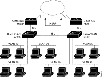
A separate HSRP group is configured for each VLAN subnet so that Cisco IOS router A can be the primary and forwarding router for VLANs 10 and 20. At the same time, it acts as backup for VLANs 30 and 40. Conversely, Router B acts as the primary and forwarding router for ISL VLANs 30 and 40, as well as the secondary and backup router for distributed VLAN subnets 10 and 20.
Running HSRP over ISL allows users to configure redundancy between multiple routers that are configured as front ends for VLAN IP subnets. By configuring HSRP over ISLs, users can eliminate situations in which a single point of failure causes traffic interruptions. This feature inherently provides some improvement in overall networking resilience by providing load balancing and redundancy capabilities between subnets and VLANs.
To configure HSRP over ISLs between VLANs, you need to create the environment in which it will be used. Perform these tasks in the order in which they appear.
To define the encapsulation format as ISL, perform these tasks in interface configuration mode:
After you have specified the encapsulation format, define the IP address over which HSRP will be routed. Perform this task in interface configuration mode:
| Task | Command |
|---|---|
| Specify the IP address for the subnet on which ISL will be used. | ip address ip-address mask [secondary] |
To enable HSRP on an interface, enable the protocol, then customize it for the interface. Perform this task in interface configuration mode:
| Task | Command |
|---|---|
| Enable HSRP. | standby [group-number] ip [ip-address [secondary]] |
To customize "hot standby" group attributes, perform one or more of these tasks in interface configuration mode:
The IPX Routing over ISL Virtual LANs (VLANs) feature extends Novell NetWare routing capabilities to include support for routing all standard IPX encapsulations for Ethernet frame types in VLAN configurations. Users with Novell NetWare environments can now configure any one of the four IPX Ethernet encapsulations to be routed using the Inter-Switch Link (ISL) encapsulation across VLAN boundaries. IPX encapsulation options now supported for VLAN traffic include
NetWare users can now configure consolidated VLAN routing over a single VLAN trunking interface. With configurable Ethernet encapsulation protocols, users have the flexibility of using VLANs regardless of their NetWare Ethernet encapsulation. Configuring Novell IPX encapsulations on a per-VLAN basis facilitates migration between version of Netware. NetWare traffic can now be routed across VLAN boundaries with standard encapsulation options (arpa, sap, and snap) previously unavailable. Encapsulation types and corresponding framing types are described in the "Configuring Novell IPX" chapter of the Network Protocols Configuration Guide, Part 2.
To configure Cisco IOS software on a router with connected VLANs to exchange different IPX framing protocols, perform these tasks in the order in which they are appear:
To enable IPX routing on ISL interfaces, perform this task in global configuration mode:
| Task | Command |
|---|---|
| Enable IPX routing globally. | ipx routing [node] |
To define the encapsulation format as ISL, perform these tasks in interface configuration mode:
| Task | Command |
|---|---|
| Specify the IPX encapsulation. | ipx network network encapsulation encapsulation-type |
With the introduction of the VIP Distributed ISL feature, Inter-Switch Link (ISL) encapsulated IP packets can be switched on Versatile Interface Processor (VIP) controllers installed on Cisco 7500 series routers.
The second generation Versatile Interface Processor (VIP2) provides distributed switching of IP encapsulated in ISL in VLAN configurations. Where an aggregation route performs inter-VLAN routing for multiple VLANs, traffic can be switched autonomously on-card or between cards rather than through the central Route Switch Processor (RSP). Figure 11 shows the VIP distributed architecture of the Cisco 7500 series router.
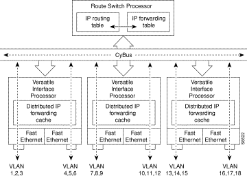
VIP distributed switching offloads switching of ISL VLAN IP traffic to the VIP card, removing involvement from the main CPU. Offloading ISL traffic to the VIP card, significantly improves networking performance. Because you can install multiple VIP cards in a router, VLAN routing capacity is increased linearly according to the number of VIP cards installed in the router.
To configure distributed switching on the VIP, you must first configure the router for IP routing. Perform these tasks in the order in which they appear:
To enable IP routing, perform this task in global configuration mode:
| Task | Command |
|---|---|
| Enable IP routing on the router. | ip routing |
Once you have IP routing enabled on the router, you can customize the characteristics to suit your environment. Refer to the IP configuration chapters in the Network Protocols configuration Guide, Part 1 for guidelines on configuring IP.
To enable VIP distributed switching, perform the following tasks beginning in interface configuration mode:
To configure ISL encapsulation on the subinterface, perform these tasks in interface configuration mode:
XNS can be routed over virtual LAN (VLAN) subinterfaces using the ISL VLAN encapsulation protocol. The XNS Routing over ISL Virtual LANs feature provides full-feature Cisco IOS software XNS support on a per-VLAN basis, allowing standard XNS capabilities to be configured on VLANs.
To route XNS over ISL VLANs you need to configure ISL encapsulation on the subinterface. Perform these tasks in the order in which they appear:
Begin the XNS routing configuration in global configuration mode:
| Task | Command |
|---|---|
| Enable XNS routing globally. |
To define the VLAN encapsulation format, perform these tasks in interface configuration mode:
| Task | Command |
|---|---|
| Enable XNS routing on the subinterface | xns network [number] |
This section provides configuration examples for each of the protocols described in this chapter. It includes these examples:
The configuration example illustrated in Figure 12 shows AppleTalk being routed between different ISL and IEEE 802.10 VLAN encapsulating subinterfaces.
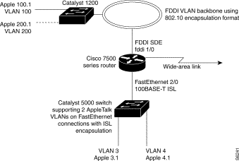
As shown in Figure 12, AppleTalk traffic is routed to and from switched VLAN domains 3, 4, 100, and 200 to any other AppleTalk routing interface. This example shows a sample configuration file for the Cisco 7500 series router with the commands entered to configure the network shown in Figure 12.
!
appletalk routing
interface Fddi 1/0.100
 encapsulation sde 100
 appletalk cable-range 100-100 100.2
 appletalk zone 100
!
interface Fddi 1/0.200
 encapsulation sde 200
 appletalk cable-range 200-200 200.2
 appletalk zone 200
!
interface FastEthernet 2/0.3
 encapsulation isl 3
 appletalk cable-range 3-3 3.2
 appletalk zone 3
!
interface FastEthernet 2/0.4
 encapsulation isl 4
 appletalk cable-range 4-4 4.2
 appletalk zone 4
!
To configure routing of the Banyan VINES protocol over ISL trunks, you need to define ISL as the encapsulation type. This example shows Banyan VINES configured to be routed over an ISL trunk:
vines routing
interface fastethernet 0.1
 encapsulation isl 100
 vines metric 2
To configure routing the DECnet protocol over ISL trunks, you need to define ISL as the encapsulation type. This example shows DECnet configured to be routed over an ISL trunk:
decnet routing 2.1
interface fastethernet 1/0.1
 encapsulation isl 200
 decnet cost 4
The configuration example shown in Figure 13 shows HSRP being used on two VLAN routers sending traffic to and from ISL VLANs through a Catalyst 5000 switch. Each router forwards its own traffic and acts as a standby for the other.
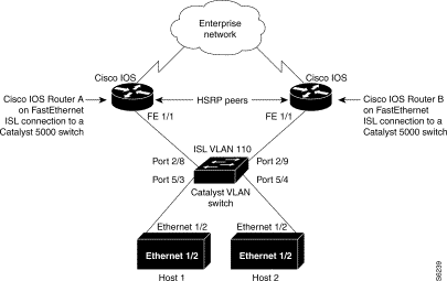
The topology shown in Figure 13 illustrates a Cisco Catalyst VLAN switch supporting Fast Ethernet connections to two routers running HSRP. Both routers are configured to route HSRP over ISLs.
The standby conditions are determined by the standby commands used in the configuration. Traffic from Host 1 is forwarded through Router A. Because the priority for the group is higher, Router A is the active router for Host 1. Because the priority for the group serviced by Host 2 is higher in Router B, traffic from Host 2 is forwarded through Router B, making Router B its active router.
In the configuration shown in Figure 13, if the active router becomes unavailable, the standby router assumes active status for the additional traffic and automatically routes the traffic normally handled by the router that has become unavailable.
interface Ethernet 1/2
 ip address 110.1.1.25 255.255.255.0
 ip route 0.0.0.0 0.0.0.0 110.1.1.101
interface Ethernet 1/2
 ip address 110.1.1.27 255.255.255.0
 ip route 0.0.0.0 0.0.0.0 110.1.1.102
!
interface FastEthernet 1/1.110
 encapsulation isl 110
 ip address 110.1.1.2 255.255.255.0
 standby 1 ip 110.1.1.101
 standby 1 preempt
 standby 1 priority 105
 standby 2 ip 110.1.1.102
 standby 2 preempt
!
end
!
interface FastEthernet 1/1.110
 encapsulation isl 110
 ip address 110.1.1.3 255.255.255.0
 standby 1 ip 110.1.1.101
 standby 1 preempt
 standby 2 ip 110.1.1.102
 standby 2 preempt
 standby 2 priority 105
router igrp 1
!
network 110.1.0.0
network 120.1.0.0
!
set vlan 110 5/4
set vlan 110 5/3
set trunk 2/8 110
set trunk 2/9 110
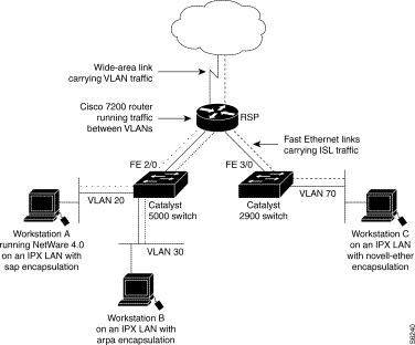
Figure 14 shows IPX interior encapsulations configured over ISL encapsulation in VLAN configurations. Note that three different IPX encapsulation formats are used. VLAN 20 uses sap encapsulation, VLAN 30 uses arpa, and VLAN 70 uses novell-ether encapsulation. Prior to the introduction of this feature, only the default encapsulation format, "novell-ether," was available for routing IPX over ISLlinks in VLANs.
ipx routing
interface FastEthernet 2/0
 no shutdown
interface FastEthernet 2/0.20
 encapsulation isl 20
 ipx network 20 encapsulation sap
ipx routing
interface FastEthernet 2/0
 no shutdown
interface FastEthernet 2/0.30
 encapsulation isl 30
 ipx network 30 encapsulation arpa
ipx routing
interface FastEthernet 3/0
 no shutdown
interface Fast3/0.70
 encapsulation isl 70
 ipx network 70 encapsulation novell-ether
Figure 15 illustrates a topology in which Catalyst VLAN switches are connected to routers forwarding traffic from a number of ISL VLANs. With the VIP distributed ISL capability in the Cisco 7500 series router, each VIP card can route ISL-encapsulated VLAN IP traffic. The inter-VLAN routing capacity is increased linearly by the packet-forwarding capability of each VIP card.
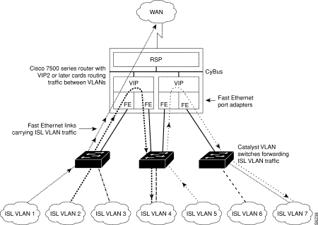
In Figure 15, the VIP cards forward the traffic between ISL VLANs or any other routing interface. Traffic from any VLAN can be routed to any of the other VLANs, regardless of which VIP card receives the traffic.
These commands show the configuration for each of the VLANs shown in Figure 15:
interface FastEthernet1/0/0
 ip address 20.1.1.1 255.255.255.0
 ip route-cache distributed
 full-duplex
interface FastEthernet1/0/0.1
 ip address 22.1.1.1 255.255.255.0
 encapsulation isl 1
interface FastEthernet1/0/0.2
 ip address 22.1.2.1 255.255.255.0
 encapsulation isl 2
interface FastEthernet1/0/0.3
 ip address 22.1.3.1 255.255.255.0
 encapsulation isl 3
interface FastEthernet1/1/0
 ip route-cache distributed
 full-duplex
interface FastEthernet1/1/0.1
 ip address 77.1.1.1 255.255.255.0
 encapsulation isl 4
interface Fast Ethernet 2/0/0
 ip address 30.1.1.1 255.255.255.0
 ip route-cache distributed
 full-duplex
interface FastEthernet2/0/0.5
 ip address 33.1.1.1 255.255.255.0
 encapsulation isl 5
interface FastEthernet2/1/0
 ip address 40.1.1.1 255.255.255.0
 ip route-cache distributed
 full-duplex
interface FastEthernet2/1/0.6
 ip address 44.1.6.1 255.255.255.0
 encapsulation isl 6
interface FastEthernet2/1/0.7
 ip address 44.1.7.1 255.255.255.0
 encapsulation isl 7
To configure routing of the XNS protocol over ISL trunks, you need to define ISL as the encapsulation type. This example shows XNS configured to be routed over an ISL trunk.
xns routing 0123.4567.adcb
interface fastethernet 1/0.1
 encapsulation isl 100
 xns network 20
|
|