|
|

Some Cisco SwitchProbe devices require a fiber-optic splitter tap to monitor the network in full-duplex mode. One fiber-optic splitter tap is included with the device.
This document provides instructions for installing the fiber-optic splitter tap. The splitter tap is passive—link integrity is maintained whether the device is on or off.
The fiber-optic splitter tap kit consists of the following items:
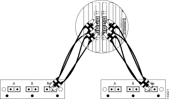
The fiber-optic splitter tap (Figure 1) contains three female SC duplex connection ports, labeled A, B, and Probe.
To connect the full-duplex 100BaseFX ports of the Multiport Fast Ethernet SwitchProbe device to two switches, follow these steps:
Step 1 Connect a fiber-optic splitter tap to the full-duplex 100BaseFX ports.
Step 2 Connect a fiber-optic splitter tap to the two switches.
The fiber-optic splitter tap kit includes a four-foot SC-duplex-to-dual-SC-duplex multimode fiber-optic cable.
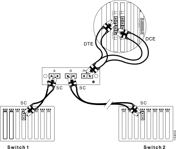
The multimode duplex SC connectors only contain receive (Rx) connections. To connect the fiber-optic splitter tap to full-duplex 100BaseFX ports, see Figure 2 and follow these steps:
Step 1 Insert one end of the dual fiber-optic cable labeled DTE into the top port of a full-duplex 100BaseFX interface (the top port is the DTE port).
Step 2 Insert the other end of the dual fiber-optic cable labeled DCE into the bottom port of the same full-duplex 100BaseFX interface (the bottom port is the DCE port).
Step 3 Insert the end of the fiber-optic cable (the cable with only one connector) into the port labeled Probe on the fiber-optic splitter tap.
Step 4 Repeat the procedure for each tap unit.

After you connect the SwitchProbe device to the tap, you must connect the tap to the network segment.
Depending on the type of cable you used between each switch and the tap, there are three possible configurations to connect the two switches to the fiber-optic splitter tap:
To connect a 100BaseFX network with SC connectors to a fiber-optic splitter tap, see Figure 3 and follow these steps:
Step 1 Switch 1 and Switch 2 are connected with a cable during network operation. Disconnect the cable from Switch 1 so only Switch 2 has a cable attached to it.
Step 2 Connect the end of this cable (Switch 2) to interface B of the fiber-optic splitter tap.
Step 3 Use the SC-to-SC cable originally included with the SwitchProbe device to connect Switch 1 to interface A of the fiber-optic splitter tap.

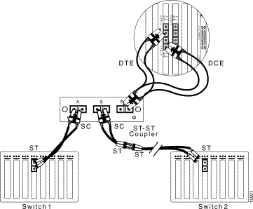
To connect a 100BaseFX network with ST connectors to a fiber-optic splitter tap, see Figure 4 and follow these steps:
Step 1 Switch 1 and Switch 2 are connected with a cable during network operation. Disconnect the cable from Switch 1 so only Switch 2 has a cable attached to it.
Step 2 Connect the end of this cable (Switch 2) to the ST-to-ST coupler.
Step 3 Use the SC-to-ST cable included with this kit to connect the ST-to-ST coupler to interface B of the fiber-optic splitter tap. (Plug the ST connector into the ST-to-ST coupler and plug the SC connector into the tap.)
Step 4 Use the SC-to-ST cable included with the SwitchProbe device to connect Switch 1 to interface A of the fiber-optic splitter tap. (Plug the ST connector into Switch 1 and plug the SC connector into the tap.)

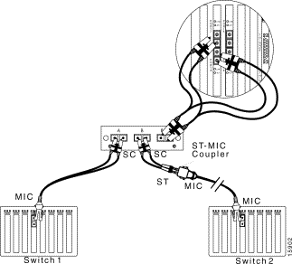
To connect a 100BaseFX network with MIC to a fiber-optic splitter tap, see Figure 5, and follow these steps:
Step 1 Switch 1 and Switch 2 are connected with a cable during network operation. Disconnect the cable from Switch 1 so only Switch 2 has a cable attached to it.
Step 2 Connect the end of this cable (Switch 2) to the ST-to-MIC coupler.
Step 3 Use the SC-to-ST cable included with this kit to connect the ST-to-MIC coupler to interface B of the fiber-optic splitter tap. (Plug the ST connector into the ST-to-MIC coupler and plug the SC connector into the tap.)
Step 4 Use the SC-to-MIC cable included with the SwitchProbe device to connect Switch 1 to interface A of the fiber-optic splitter tap. (Plug the MIC connector into Switch 1 and plug the SC connector into the tap.)

Cisco Connection Online (CCO) is Cisco Systems' primary, real-time support channel. Maintenance customers and partners can self-register on CCO to obtain additional information and services.
Available 24 hours a day, 7 days a week, CCO provides a wealth of standard and value-added services to Cisco's customers and business partners. CCO services include product information, product documentation, software updates, release notes, technical tips, the Bug Navigator, configuration notes, brochures, descriptions of service offerings, and download access to public and authorized files.
CCO serves a wide variety of users through two interfaces that are updated and enhanced simultaneously: a character-based version and a multimedia version that resides on the World Wide Web (WWW). The character-based CCO supports Zmodem, Kermit, Xmodem, FTP, and Internet e-mail, and it is excellent for quick access to information over lower bandwidths. The WWW version of CCO provides richly formatted documents with photographs, figures, graphics, and video, as well as hyperlinks to related information.
You can access CCO in the following ways:
For a copy of CCO's Frequently Asked Questions (FAQ), contact cco-help@cisco.com. For additional information, contact cco-team@cisco.com.
Cisco documentation and additional literature are available in a CD-ROM package, which ships with your product. The Documentation CD-ROM, a member of the Cisco Connection Family, is updated monthly. Therefore, it might be more current than printed documentation. To order additional copies of the Documentation CD-ROM, contact your local sales representative or call customer service. The CD-ROM package is available as a single package or as an annual subscription. You can also access Cisco documentation on the World Wide Web at http://www.cisco.com, http://www-china.cisco.com, or http://www-europe.cisco.com.
If you are reading Cisco product documentation on the World Wide Web, you can submit comments electronically. Click Feedback in the toolbar and select Documentation. After you complete the form, click Submit to send it to Cisco. We appreciate your comments.

![]()
![]()
![]()
![]()
![]()
![]()
![]()
![]()
Posted: Fri Sep 6 19:54:37 PDT 2002
All contents are Copyright © 1992--2002 Cisco Systems, Inc. All rights reserved.
Important Notices and Privacy Statement.