|
|

This document describes the procedure for installing random-access memory (RAM) in small (PB6), large (PB7), and front-access (PB8) SwitchProbe devices.
This document includes the following sections:
 | Warning This warning symbol means danger. You are in a situation that could cause bodily injury. Before you work on any equipment, be aware of the hazards involved with electrical circuitry and be familiar with standard practices for preventing accidents. |
 | Caution Means reader be careful. In this situation, you might do something that could result in equipment damage or loss of data. |
To see translations of the warnings that appear in this document, see the appendix "Translated Safety Warnings" in the Cisco SwitchProbe Installation and Configuration Guide.
 | Warning Only trained and qualified personnel should be allowed to install, replace, or service this equipment. |
 | Warning Before working on a system that has an on/off switch, turn OFF the power and unplug the power cord. |
 | Warning Before opening the chassis, disconnect the telephone-network cables to avoid contact with telephone-network voltages. |
 | Warning Do not work on the system or connect or disconnect cables during periods of lightning activity. |
 | Warning Do not touch the power supply when the power cord is connected. For systems with a power switch, line voltages are present within the power supply even when the power switch is off and the power cord is connected. For systems without a power switch, line voltages are present within the power supply when the power cord is connected. |
 | Warning Before working on equipment that is connected to power lines, remove jewelry (including rings, necklaces, and watches). Metal objects will heat up when connected to power and ground and can cause serious burns or weld the metal object to the terminals. |
 | Warning Ultimate disposal of this product should be handled according to all national laws and regulations. |
The SwitchProbe memory installation kits contain the following items:
| Upgrade To | How Supplied | Installation Instructions |
|---|---|---|
16 MB | Two 8 MB SIMMs | Note This combination of SIMMs is provided only for small (PB6) devices.
Remove the existing SIMMs and replace them with the two 8 MB SIMMs provided in the installation kit. |
32 MB | Two 16 MB SIMMs | Remove the existing SIMMs and replace them with the two 16 MB SIMMs provided in the installation kit. |
64 MB | Two 32 MB SIMMs | Remove the existing SIMMs and replace them with the two 32 MB SIMMs provided in the installation kit. See "Installing Memory in Front-Access (PB8) SwitchProbe Devices". |
Electrostatic discharge (ESD) is the release of stored static electricity that can damage electrical circuitry. Static electricity is often stored in your body, and discharged when you come in contact with an object with a different potential. The ESD wrist strap safely channels this electricity from your body to a proper ground.
 | Warning Before working on a system that has an on/off switch, turn OFF the power and unplug the power cord. |
 | Caution The SwitchProbe device is no longer grounded after you remove the power supply. Therefore, you must ground to something other than the chassis, such as a different chassis or another piece of equipment that is plugged in and grounded. Make sure the equipment having a grounding type plug is properly grounded. |
Use an ESD wrist strap whenever you open a chassis, particularly when you will be handling circuit cards and appliques. To work properly, the wrist strap must make good contact at both ends—with your skin at one end, and with a proper ground at the other.
To use the ESD wrist strap correctly, follow these steps:
Step 1 Ensure that the equipment is properly grounded.
 | Caution Make certain that you are not in contact with grounded objects other than through the wrist strap. |
Step 2 Turn the chassis power switch OFF.
Step 3 Unplug the power cord.
Step 4 Make sure the wrist strap is grounded.
Step 5 Remove the wrist strap from the bag and note the following:
Step 6 Snap the cable fastener at the end of the coiled ground cord onto the wrist band.
 | Caution A one megaohm resistor is located in the wrist strap ground cord. Do not remove the resistor. If it becomes damaged, replace the ground cord immediately. |
Step 7 Slip the wrist band firmly around your wrist for a snug fit.
Step 8 Connect the alligator clip to the device that you are using as a ground.
Figures 1 and 2 show the front and rear panels of a small (PB6) SwitchProbe device.

To install memory in a PB6 device, follow these steps:
 | Warning During this procedure, wear a grounding wrist strap to avoid ESD damage to the card. Do not directly touch the backplane with your hand or any metal tool, or you could shock yourself. |
Step 1 Put on the ESD wrist strap, following the instructions in the "Electrostatic Discharge Wrist Strap Instructions" section.
Step 2 Turn off the power to the SwitchProbe device.
Step 3 Remove all cables from the back of the chassis, including the power cable.
Step 4 Turn the chassis upside-down.
Step 5 Remove the four screws located near the edges of the chassis (Figure 3).

Step 6 Turn the device right-side up.
Step 7 Remove the top cover by moving it upward and away from the back panel.
 | Warning Do not touch the power supply when the power cord is connected. For systems with a power switch, line voltages are present within the power supply even when the power switch is off and the power cord is connected. For systems without a power switch, line voltages are present within the power supply when the power cord is connected. |
Step 8 Disconnect the green/yellow ground wire from the power supply.
Step 9 Remove the power supply by removing the four screws (Figure 4).
Step 10 Place the power supply to the side of the chassis, using care not to stress the existing wiring.
Step 11 Remove any card residing in slot 3 to gain access to the memory. ( Memory is located beneath slot 3.)
Step 12 Remove the installed memory (Figure 5).
 | Caution Do not use excessive force because the connector could break. |
Step 13 Install the SIMMs provided with the installation kit by sliding the end of the SIMM card with the metal fingers straight down into the SIMM connector socket, at an angle perpendicular to the card.
Step 14 Gently rock the SIMM back and snap it into place (Figure 6).
 | Caution Do not use excessive force because the connector could break. |

Step 15 Install the slot 3 NIC card.
Step 16 Return the power supply to its original location inside the chassis.
Step 17 Use the original hardware to connect the power supply to the device.
Step 18 Secure the green/yellow ground wire to the power supply, closest to the inside of the device.
Step 19 Reassemble the unit.
Step 20 Remove the ESD wrist strap.
Step 21 Power up the unit to verify successful boot sequence.
Step 22 Check the new memory configuration on the console port.
Step 23 Place the new "Warranty Void if Seal is Broken" label over the old, torn label.
Figures 7 and 8 show the front and rear panels of a large (PB7) SwitchProbe device.


To install memory in a PB7 device, follow these steps:
 | Warning During this procedure, wear a grounding wrist strap to avoid ESD damage to the card. Do not directly touch the backplane with your hand or any metal tool, or you could shock yourself. |
Step 1 Put on the ESD wrist strap, following the instructions in the "Electrostatic Discharge Wrist Strap Instructions" section.
Step 2 Turn off the power to the SwitchProbe device.
Step 3 Remove all cables from the back of the chassis, including the power cable.
Step 4 Turn the chassis so that the rear of the chassis is facing you.
Step 5 Remove the three screws located at the edge of the case (Figure 9).
Step 6 Remove the top cover by moving it upward and away from the back panel.

Step 7 Remove the installed memory (Figure 10).
 | Caution Do not use excessive force because the connector could break. |
Step 8 Install the SIMMs provided with the installation kit by sliding the end of the SIMM card with the metal fingers straight down into the SIMM connector socket, at an angle perpendicular to the card.
Step 9 Gently rock the SIMM back and snap it into place (Figure 11).
 | Caution Do not use excessive force because the connector could break. |

Step 10 Reassemble the unit.
Step 11 Remove the ESD wrist strap.
Step 12 Power up the unit to verify successful boot sequence.
Step 13 Check the new memory configuration on the console port.
Step 14 Place the new "Warranty Void if Seal is Broken" label over the old, torn label.
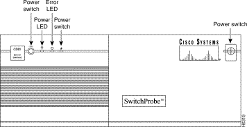
Figure 12 shows the front panel of a front-access (PB8) 64MB SwitchProbe device.

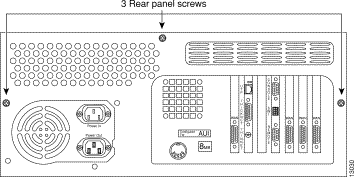
Depending on SwitchProbe model you have, Figures 13 and 14 show the rear panel of a front-access chassis SwitchProbe device.

To install memory in a PB8 device, follow these steps:
 | Warning .During this procedure, wear a grounding wrist strap to avoid ESD damage to the card. Do not directly touch the backplane with your hand or any metal tool, or you could shock yourself. |
Step 1 Put on the ESD wrist strap, following the instructions in ""Electrostatic Discharge Wrist Strap Instructions" section.
Step 2 Turn off the power to the SwitchProbe device.
Step 3 Remove all cables from the chassis, including the power cable.
Step 4 Turn the chassis so that the rear of the chassis is facing you.
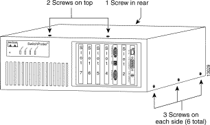
Step 5 Remove the nine screws.
There are three screws on each side, one in the rear, and two on the top surface of the chassis (Figure 15).
Step 6 Remove the top cover by lifting the rear and pulling up.

Step 7 Remove the installed memory (Figure 16).
Step 8 Install the SIMMs provided with the installation kit by sliding the end of the SIMM card with the metal fingers straight down into the SIMM connector socket, at an angle perpendicular to the card.
Step 9 Gently rock the SIMM back and snap it into place (Figure 17).
 | Caution Do not use excessive force because the connector could break. |
Step 10 Reassemble the unit.
Step 11 Remove the ESD wrist strap.
Step 12 Power up the unit to verify successful boot sequence.
Step 13 Check the new memory configuration on the console port.
Step 14 Place the new "Warranty Void if Seal is Broken" label over the old, torn label.
Cisco documentation and additional literature are available in a CD-ROM package, which ships with your product. The Documentation CD-ROM, a member of the Cisco Connection Family, is updated monthly. Therefore, it might be more current than printed documentation. To order additional copies of the Documentation CD-ROM, contact your local sales representative or call customer service. The CD-ROM package is available as a single package or as an annual subscription. You can also access Cisco documentation on the World Wide Web at http://www.cisco.com, http://www-china.cisco.com, or http://www-europe.cisco.com.
If you are reading Cisco product documentation on the World Wide Web, you can submit comments electronically. Click Feedback in the toolbar and select Documentation. After you complete the form, click Submit to send it to Cisco. We appreciate your comments.
Cisco Connection Online (CCO) is Cisco Systems' primary, real-time support channel. Maintenance customers and partners can self-register on CCO to obtain additional information and services.
Available 24 hours a day, 7 days a week, CCO provides a wealth of standard and value-added services to Cisco's customers and business partners. CCO services include product information, product documentation, software updates, release notes, technical tips, the Bug Navigator, configuration notes, brochures, descriptions of service offerings, and download access to public and authorized files.
CCO serves a wide variety of users through two interfaces that are updated and enhanced simultaneously: a character-based version and a multimedia version that resides on the World Wide Web (WWW). The character-based CCO supports Zmodem, Kermit, Xmodem, FTP, and Internet e-mail, and it is excellent for quick access to information over lower bandwidths. The WWW version of CCO provides richly formatted documents with photographs, figures, graphics, and video, as well as hyperlinks to related information.
You can access CCO in the following ways:
For a copy of CCO's Frequently Asked Questions (FAQ), contact cco-help@cisco.com. For additional information, contact cco-team@cisco.com.
![]()
![]()
![]()
![]()
![]()
![]()
![]()
![]()
Posted: Wed Oct 30 09:42:33 PST 2002
All contents are Copyright © 1992--2002 Cisco Systems, Inc. All rights reserved.
Important Notices and Privacy Statement.