|
|

The following lessons help you learn how to use QoS Policy Manager (QPM) and how to create and distribute QoS policies and configurations:
Use Policy Manager to create and edit QoS policies and configurations. These sections describe the basics for how to use Policy Manager:
Start Policy Manager to create, change, delete, and view your QoS configuration and policies.
If you are not already logged into QPM, QPM opens the Logon Information window.
Step 2 Log into QPM. You must enter a QPM user name and password according to these requirements:
If you enter a correct name and password, Policy Manager starts and automatically opens the last QoS database that was open.
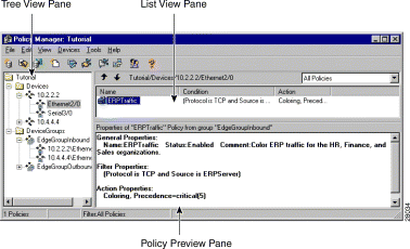
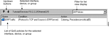
The main Policy Manager window (Figure 3-1) is divided into three panes.
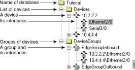
The tree view pane (Figure 3-2) contains folders for each device you are managing in the Devices folder. Most device folders contain a list of interfaces on which you define QoS policies. For some devices, you define policies directly on the device folder.
The tree view also contains a Device Groups folder, which contains the device groups you have defined. Device groups are groups of interfaces that you intend to manage using identical policies. You must treat all interfaces in a device group identically.
The tree view pane is where you start when creating a policy. If the device is not yet defined in the QoS database, you must first define it and add its interfaces. If the device is already defined in the QoS database, you must select the folder (usually an interface) on which you want to define a policy before you can create (or change) the policy.
The list view pane (Figure 3-3) shows the policies that are defined on the interface, device, or device group selected in the tree view.
If you select an interface that belongs to a device group, the list of policies includes those defined on the device group as well as those defined directly on the interface. You cannot edit or change the order of group policies when viewing them from a member interface. Group policies are always given lower priority than individual interface policies.
Each policy is preceded by an icon that indicates the status of the policy. Table 3-1 describes these icons.
The top bar of the list view includes these items:
The policy preview pane displays a summary of the policy selected in the list pane. This can help you determine if you have defined your filter conditions correctly. The policy expression is only displayed if you have selected View>Policy Preview.
You can use the standard Windows cut, copy, and paste functions to manipulate policies in the QPM list pane.
Step 2 Use these commands to cut, copy, or paste.
You can change the main Policy Manager window to display information according to your preferences. Table 3-2 lists the available commands for changing the main Policy Manager window.
Table 3-2 Changing the Policy Manager Main Window
You must periodically save your changes to the QoS database. However, saving your changes to the database does not apply those changes to the network. You must use Distribution Manager to deploy your new or changed policies to the network.
If the QoS Manager service is not available when you try to save the database, the database is saved to your local disk. Check the machine that is running QoS Manager to ensure it is running properly and try saving the database again.
From the Policy Manager interface, you can close just Policy Manager, or exit both Policy Manager and Distribution Manager.
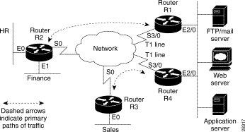
Figure 3-4 shows the network used in subsequent lessons to illustrate how to use QoS Policy Manager to create and deploy QoS policies.
This network has three areas that we will concentrate on.
1. The segments that contain the major servers used in the network. These servers are connected to the network through routers R1 and R4.
2. The segments that contain the HR and Finance users, connected to the network through router R2. The HR and Finance users primarily use the Enterprise Resource Planning (ERP) application server, but they do not use the web server as a significant part of their network usage. They also use the FTP/Mail server.
3. The segments that contain the Sales users, connected to the network through router R3. The Sales users use both the ERP application and web server as a significant part of their network usage. They also use the FTP/Mail server.
Table 3-3 lists the other technical details of the network that you need to know to follow the lessons. Not all interfaces on the devices are listed.
Table 3-3 Technical Network Details for Lessons
|
Other interface and device addresses might be used in the lessons.
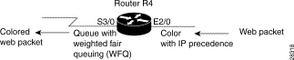
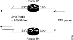
In this lesson, you will learn how to add a router to the QoS database and create and deploy a simple policy. The policy in this example sets the IP precedence for web traffic that goes through router R4 (see Figure 3-4 for the overall network diagram). The purpose of this policy is to color the web traffic for the Sales group, because the web server behind R4 hosts a significant application used by Sales, and Sales requires good response from this server.
In order to make a meaningful policy, we must not only color the traffic on the inbound interface to the router (interface Ethernet2/0, which connects the web server to R4), but we must choose a QoS property for the outbound interface Serial3/0 (Figure 3-5). We will implement weighted fair queuing (WFQ). This ensures that the packet coloring we perform on Ethernet3/0 is used by the router.
At the end of this lesson, you should be able to
If you want to create a policy and deploy it on a router that exists in your network, obtain the IP address of an appropriate router. Otherwise, you can use the IP addresses in this lesson so that you can follow these steps without affecting your network.
The lesson assumes that you are starting with an empty database.
QPM opens the New Device window.
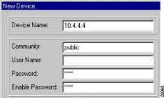
In our example, router R4 is 10.4.4.4, the community string is public, and both passwords are test (Figure 3-6).
(c). If the device is online, ensure that the Verify Device Information and Detect Interfaces check boxes are selected and click OK.
QPM queries the device, fills in the Device Model and Software Revision fields, and obtains a list of the device's interfaces. QPM opens the Detect Interfaces window when it has a complete list of interfaces.
In the Detect Interfaces window, ensure that the interfaces you want to manage are in the selected interfaces list, and move any you do not want to manage to the available interfaces list. In this lesson, we are only going to manage Ethernet2/0 and Serial3/0. Click OK when finished.
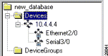
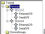
QPM creates a folder for the router in the tree view using the IP address of the router. The router's interfaces are included as members of this folder.
(d). If the device is not online (for example, if you are using the IP addresses used in this lesson instead of addresses for devices on your network), you must fill in the Software Version and Device Model fields manually. In our example, router R4 is a Cisco 7200 running IOS software release 11.2.
Deselect the Verify Device Information and Detect Interfaces check boxes, so that QPM does not try to query the device.
Then, click Define Interface. QPM opens the New Interface window. Enter the details for the Ethernet2/0 interface and then repeat the process for the Serial3/0 interface (see Table 3-3 for this information).
Figure 3-7 shows the tree view that now includes router R4.
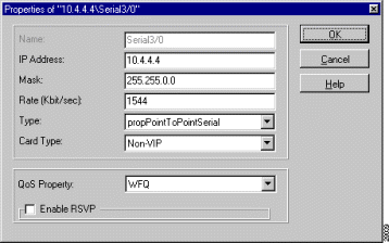
Step 2 Configure the QoS property on the Serial3/0 interface so that it uses weighted fair queuing. We do not need to change the QoS property of the Ethernet2/0 interface because we are only creating a policy for inbound traffic for Ethernet2/0.
QPM opens the Properties of Interface window.
(b). Select WFQ in QoS Property (Figure 3-8) and click OK.
Step 3 Define a policy to color web traffic on the inbound interface (Ethernet2/0 on router R4).
(a). Select the Ethernet2/0 interface in the tree view.
(b).  Click the New Policy button, or select File>New>Policy.
QPM opens the Properties of Policy window, in which you will create the policy.
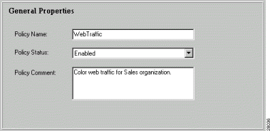
(c). In the General Properties page, change the name of the policy and add a meaningful comment. For this policy, use "WebTraffic" and "Color web traffic for Sales organization." Figure 3-9 shows the completed general properties.
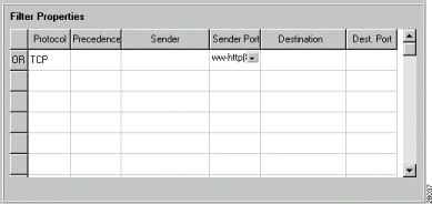
In the filters list, select these values in the same row to indicate the policy is for inbound web traffic:
These are the only conditions required to identify web traffic. Figure 3-10 shows the completed filter properties.
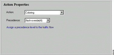
Select Coloring in the Action field. When you select a policy action, QPM displays the possible settings for that action. These settings can differ even for the same action depending on the software running on the device.
In this case, QPM adds the Precedence field. Select 4 in the Precedence field to give a higher priority to the traffic that satisfies the policy's filter. Figure 3-10 shows the completed action properties.
QPM adds the policy to the Serial3/0 folder.
Step 4  Click the Save button, or select File>Save, to save your policy changes. Because this is the first time you have saved the database, you are prompted to name it. We will name this database Tutorial. Type Tutorial in the Database Name field in the Save Database window and click OK.
Step 5 Distribute your policies to the network.
(a).  Click the Distribution Manager button, or select Tools>Distribution Manager, to start Distribution Manager.
(b). In Distribution Manager, select Devices>Create Job to create a distribution job from the Tutorial database.
QPM opens the Create Job window.
QPM creates a distribution job based on the policy definitions in the selected database. The job consists of the commands required to reconfigure the devices to implement your policies. Only the changes made since you last distributed the database are included in the job.
When you select the job, QPM displays the contents of the job in the list view, which shows the devices whose configurations will be changed by the job. If you double-click the device name in the list view, QPM displays the commands that will be sent to the device when you apply the job (the device must be available on the network).
QPM starts applying the changes defined in the job to the network devices. You can view the results of the jobs in the logs displayed in the bottom pane of Distribution Manager.
In this lesson, you will learn how to treat a set of device interfaces as a group, and create and deploy a simple policy across the members of that group. The policy in this example will set the IP precedence for Enterprise Resource Planning (ERP) traffic that goes through routers R1 and R4 (see Figure 3-4 for the overall network diagram). The purpose of this policy is to color the ERP traffic for the HR, Finance, and Sales organizations, because the ERP servers behind R1 and R4 host significant applications used by these organizations, and they require good response from this server.
In order to make a meaningful policy, we must not only color the traffic on the incoming interfaces to these routers (the Ethernet2/0 interfaces, which connect the ERP server to R1 and R4), but we must choose a QoS property for the outbound Serial3/0 interfaces (Figure 3-12). We will implement weighted fair queuing (WFQ) on the outbound interfaces. This ensures that the packet coloring we perform on Ethernet2/0 is used by the routers.
At the end of this lesson, you should be able to:
If you want to create a policy and deploy it on a device that exists in your network, obtain the IP address of an appropriate device. Otherwise, you can use the IP addresses in this lesson so that you can follow these steps without affecting your network.
This lesson assumes that you have completed the steps in the "Lesson 3—Creating a Simple Policy for Managing Web Traffic on One Router" section.
QPM opens the New Device window.
In our example, router R1 is 10.2.2.2, the community string is public, and both passwords are test.
(c). If the device is online, ensure that the Verify Device Information and Detect Interfaces check boxes are selected and click OK.
QPM queries the device, fills in the Device Model and Software Revision fields, and obtains a list of the device's interfaces. QPM opens the Detect Interfaces window when it has a complete list of interfaces.
In the Detect Interfaces window, ensure that the interfaces you want to manage are in the selected interfaces list, and move any you do not want to manage to the available interfaces list. In this lesson, we are going to manage only Ethernet2/0 and Serial3/0. Click OK when finished.
QPM creates a folder for the router in the tree view using the IP address of the router. The router's interfaces are included as members of this folder.
(d). If the device is not online (for example, if you are using the IP addresses used in this lesson instead of addresses for devices on your network), you must fill in the Software Version and Device Model fields manually. In our example, router R1 is a Cisco 7200 running IOS software release 11.2.
Deselect the Verify Device Information and Detect Interfaces check boxes, so that QPM does not try to query the device.
Then, click Define Interfaces. QPM opens the New Interface window. Enter the details for the Ethernet2/0 interface and repeat the process for the Serial3/0 interface (see Table 3-3 for this information).
Figure 3-13 shows the tree view that now includes router R1.
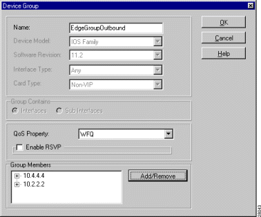
Step 2 Create a device group for the Serial3/0 interfaces on routers R1 and R4, and set the QoS property for these interfaces to weighted fair queuing.
(a). Select Devices>Device Group>New, or select the DeviceGroups folder in the tree view, right-click, and select New Device Group.
QPM opens the Device Group window.
(b). In the Device Group window, fill in these fields:
QPM opens the Add/Remove Group Members window.
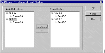
(d). In the Add/Remove Group Members window, open the trees for each device, select the Serial3/0 interfaces for each device in turn and click >> to add each interface to the group (Figure 3-14). Click OK when finished.
Figure 3-15 shows the Device Group window after you have added the Serial3/0 interfaces as group members.
QPM asks you to confirm that you want the group properties to override the properties already defined on R4's Serial3/0 interface (properties created in the "Lesson 3—Creating a Simple Policy for Managing Web Traffic on One Router" section). Click Yes.
QPM creates the group and adds it to the DeviceGroups folder in the tree view.
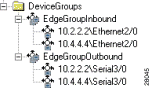
Step 3 Create a device group for the Ethernet2/0 interfaces on routers R1 and R4.
(a). Select Devices>Device Group>New, or select the DeviceGroups folder in the tree view, right-click, and select New Device Group.
QPM opens the Device Group window.
QPM opens the Add/Remove Group Members window.
(d). In the Add/Remove Group Members window, open the trees for each device, select the Ethernet2/0 interfaces for each device in turn and click >> to add each interface to the group. Click OK when finished.
QPM adds the interfaces to the Group Members list in the Device Group window.
Figure 3-16 shows the tree view with the completed device group entries.
Step 4 Create a policy on the EdgeGroupInbound group to color ERP traffic.
(a). Select the EdgeGroupInbound group in the tree pane.
(b). Click the New Policy button, or select File>New>Policy.
QPM opens the Properties of Policy window.
(c). In the General Properties page, change the name of the policy and add a meaningful comment. For this policy, use "ERPTraffic" and "Color ERP traffic for the HR, Finance, and Sales organizations."
In the filters list, select these values in the same row to indicate the policy is for inbound ERP traffic. Because the ERP server in this example is dedicated to the ERP applications, as is typically the case, we color all traffic from the server. If other applications were on the same server as the ERP application, we would also use a port filter.
Select Coloring in the Action field.
QPM adds the Precedence field. Select 5 in the Precedence field to give a higher priority to the traffic that satisfies the policy's filter.
QPM adds the policy to the EdgeGroupInbound folder.
Step 5 Click the Save button, or select File>Save, to save your policy changes. Because we used a host name for the ERP server, QPM asks if you would like the host name resolved to its IP address. Policies can be distributed to the device only if the host names are converted to IP addresses. Click Yes to have QPM resolve the host name. (Click No if you are following along in this lesson without using actual host names that exist in your network.)
Step 6 Distribute your policies to the network.
(a). Click the Distribution Manager button, or select Tools>Distribution Manager, to start Distribution Manager.
(b). In Distribution Manager, select Devices>Create Job to create a distribution job from the Tutorial database.
QPM opens the Create Job window.
QPM creates a distribution job based on the policy definitions in the selected database. The job consists of the commands required to reconfigure the devices to implement your policies. Only the changes made since you last distributed the database are included in the job.
When you select the job, QPM displays the contents of the job in the list view, which shows the devices whose configurations will be changed by the job. If you double-click the device name in the list view, QPM displays the commands that will be sent to the device when you apply the job (the device must be available on the network).
QPM starts applying the changes defined in the job to the network devices. You can view the results of the jobs in the logs displayed in the bottom pane of Distribution Manager.
In this lesson, you will learn how to limit the bandwidth that is available to a specific application. The policy in this example will limit FTP traffic that goes through the outgoing interfaces on routers R1 and R4 (see Figure 3-4 for the overall network diagram). The purpose of this policy is to prevent FTP traffic from flooding the network and thus reducing performance of the more important applications on the network.
Traffic shaping policies or limiting policies are typically used on outbound interfaces. We define an application service alias for FTP traffic from the central site, and use the alias to set the limit for FTP traffic to 200 Kbps (Figure 3-17).
At the end of this lesson, you should be able to:
If you want to create a policy and deploy it on a device that exists in your network, obtain the IP address of an appropriate device. Otherwise, you can use the IP addresses in this lesson so that you can follow these steps without affecting your network.
This lesson assumes that you have completed the steps in "Lesson 4—Coloring Enterprise Resource Planning (ERP) Traffic on a Group of Devices" section.
QPM opens the Application Services window.
QPM opens the Application Service window.
(c). In the Application Service window, fill in the required information to identify the source of the FTP traffic, and to give the application service alias a name.
In this example, we will identify the FTP traffic by using these attributes (Figure 3-18)
Click OK when finished to return to the Application Services window.
Step 2 Create a policy on the EdgeGroupOutbound interface to limit the bandwidth available to FTP traffic.
(a). Select EdgeGroupOutbound in the tree view.
(b). Click the New Policy button, or select File>New>Policy.
QPM opens the Properties of Policy window.
(c). In the General Properties page, change the name of the policy and add a meaningful comment. For this policy, use "FTP Traffic" and "Limit bandwidth for FTP traffic."
In the filters list, select the Sender field and click the drop-down button. This opens an imbedded window where you can select the type of sender. Select these values and click OK:
Select Shaping in the Action field.
QPM adds the fields for generic traffic shaping. Enter 200 in the Rate field, leaving the other fields blank. If you want, you can enter burst sizes to control the amount of data per interval sent out the interface (see Table B-15, Part 2 for details).
QPM adds the policy to the EdgeGroupOutbound folder.
Step 3 Click the Save button, or select File>Save, to save your policy changes.
Step 4 Distribute your policies to the network.
(a). Click the Distribution Manager button, or select Tools>Distribution Manager, to start Distribution Manager.
(b). In Distribution Manager, select Devices>Create Job to create a distribution job from the Tutorial database.
QPM opens the Create Job window.
QPM creates a distribution job based on the policy definitions in the selected database. The job consists of the commands required to reconfigure the devices to implement your policies. Only the changes made since you last distributed the database are included in the job.
When you select the job, QPM displays the contents of the job in the list view, which shows the devices whose configurations will be changed by the job. If you double-click the device name in the list view, QPM displays the commands that will be sent to the device when you apply the job (the device must be available on the network).
QPM starts applying the changes defined in the job to the network devices. You can view the results of the jobs in the logs displayed in the bottom pane of Distribution Manager.
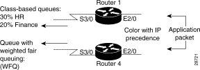
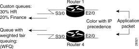
In this lesson, you will learn how to create custom queues to deliver guaranteed bandwidth to specified types of traffic. The policies in this example will guarantee bandwidth for ERP traffic for the HR and Finance groups on the outgoing interfaces on router R1 (see Figure 3-4 for the overall network diagram). The purpose of this policy is to ensure that both groups get agreed-upon performance for their ERP applications.
Custom queuing policies are only effective on outbound interfaces, because the router cannot control the flow of packets on incoming interfaces. Because we have included R1's Serial3/0 interface in a device group in a previous lesson, we must first remove it from the device group so that we can treat Serial3/0 on R1 and R4 differently (Figure 3-19).
At the end of this lesson, you should be able to
If you want to create a policy and deploy it on a device that exists in your network, obtain the IP address of an appropriate device. Otherwise, you can use the IP addresses in this lesson so that you can follow these steps without affecting your network.
This lesson assumes that you have completed the steps in "Lesson 5—Limiting the Bandwidth Available to FTP Traffic" section.
QPM opens the Host Groups window.
QPM opens the Properties of Host Group window. (Until you enter a host group name, this window is called Host Group Properties.)
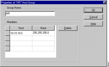
Enter the list of machines used by the HR group. You can enter the names individually, or you can use a subnet mask to cover all machines within a subnet. Click in the table cells to enter the information. In this example, we will enter a subnet:
Figure 3-20 shows the completed Properties of Host Group window for the HR group.
Click OK when finished. QPM creates the HR group and returns you to the Host Groups window.
QPM opens the Properties of Host Group window.
Enter the list of machines used by the Finance group. In this example, we will enter a subnet:
Click OK when finished. QPM creates the Finance group and returns you to the Host Groups window.
Step 2 Remove the Serial3/0 interface for router R1 from the EdgeGroupOutbound device group.
QPM opens the Add/Remove Group Members window.
(b). Select the Serial3/0 interface in the 10.2.2.2 folder and click << to remove it from the group. Click OK when finished.
QPM tells you that it will keep the group-defined QoS property for the interface, and asks you whether you want to copy group-defined policies to the interface. Select Yes, so that the FTPTraffic policy remains active on the 10.2.2.2\Serial3/0 interface.
Step 3 Change the QoS property for the 10.2.2.2\Serial3/0 interface.
(a). Select Serial3/0 in the 10.2.2.2 folder in the tree pane and select Devices>Interface>Properties.
QPM opens the Properties of Interface window.
QPM adds the Packet Size parameter to the window. This value is used to determine the byte count for the custom queues that you will create on the interface. Enter a value that is average for the packets you expect. In this example, we will use 500.
Step 4 Create the custom queue for HR on the Serial3/0 interface.
(a). Select Serial3/0 in the 10.2.2.2 folder in the tree pane.
(b). Click the New Policy button, or select File>New>Policy.
QPM opens the Properties of Policy window.
(c). In the General Properties page, change the name of the policy and add a meaningful comment. For this policy, use "HR ERPTraffic" and "Custom queue for HR's ERP traffic."
In the filters list, select these values in the same row to indicate the policy is for ERP traffic that is headed for computers in the HR subnet. Because the ERP server in this example is dedicated to the ERP applications, as is typically the case, we filter all traffic from the server. If other applications were on the same server as the ERP application, we would also use a port filter.
Select Custom Queue in the Action field.
QPM adds the fields for custom queuing. Enter 30 in the Ratio field and leave the Limit field blank. This provides 30% of the bandwidth to the HR group's ERP traffic. If you want, you can enter a limit value to limit the number of packets that can be held in the queue (the number you enter indicates the number of packets; it does not indicate the number of bytes).
QPM adds the policy to the Serial3/0 folder. You are now finished with the HR ERPTraffic policy.
Step 5 Now create the Finance ERPTraffic policy.
(a). Because the Finance ERPTraffic policy will be similar to the HR ERPTraffic policy, create a copy the HR ERPTraffic policy by right-clicking it in the list view and selecting Copy.
Then, right-click in the list view and select Paste.
QPM creates a new policy named Copy of HR ERPTraffic.
QPM opens the Properties of Policy window.
(c). In the General Properties page, change the name of the policy and update the comment. For this policy, use "Finance ERPTraffic" and "Custom queue for Finance's ERPTraffic."
In the filters list, change the Destination host group to Finance. Select the Destination field and click the drop-down button. Then select Finance for Group and click OK. Do not change the other filter elements (Protocol is TCP, Sender is ERPServer).
Change the ratio to 20. This provides 20% of the bandwidth to the Finance group's ERP traffic.
QPM adds the policy to the Serial3/0 folder. You are now finished with the Finance ERPTraffic policy.
Step 6 Click the Save button, or select File>Save, to save your policy changes. Because we used a host name for the ERP server, QPM asks if you would like the host name resolved to its IP address. Policies can only be distributed to the device if the host names are converted to IP addresses. Click Yes to have QPM resolve the host name. (Click No if you are following along in this lesson without using actual host names that exist in your network.)
Step 7 Distribute your policies to the network.
(a). Click the Distribution Manager button, or select Tools>Distribution Manager, to start Distribution Manager.
(b). In Distribution Manager, select Devices>Create Job to create a distribution job from the Tutorial database.
QPM opens the Create Job window.
QPM creates a distribution job based on the policy definitions in the selected database. The job consists of the commands required to reconfigure the devices to implement your policies. Only the changes made since you last distributed the database are included in the job.
When you select the job, QPM displays the contents of the job in the list view, which shows the devices whose configurations will be changed by the job. If you double-click the device name in the list view, QPM displays the commands that will be sent to the device when you apply the job (the device must be available on the network).
QPM starts applying the changes defined in the job to the network devices. You can view the results of the jobs in the logs displayed in the bottom pane of Distribution Manager.
In this lesson, you will learn how to update the QoS database to recognize that you have upgraded the software on a device. We will upgrade the software on routers R1 and R4 to IOS software release 12.0(5)T.
In most cases, your QoS configuration and policies remain unchanged after a software upgrade. However, in certain cases, QPM changes the implementation of policies to take advantage of the features of a new software release (without changing the meaning of your policies). Table 3-4 explains the changes that are made for some software upgrades.
Table 3-4 QPM Policy Conversions During IOS Software Upgrade
|
Upgrading the device software does not affect any device groups to which the device's interfaces belong. You must recreate the device groups if you want them to be restricted to the updated software version.
At the end of this lesson, you should be able to:
This lesson assumes that you have completed the steps in the "Lesson 6—Allocating Minimum Bandwidth to Critical Traffic Using Custom Queuing" section.
You do not have to update all your routers simultaneously.
Step 2 Start QPM and open the Tutorial database.
Step 3 Change the device properties for router R1:
QPM opens the Device Properties window.
QPM queries the router and updates the software revision number and device model, and makes policy conversions if required.
(If you are not using a real device, instead of clicking Verify Device Info, select 12.0(5)T in the Software Revision field.)
Click OK when finished to save the changes to the device configuration. If there are any conflicts between the QoS configuration and policies defined on the interfaces for the device and the new software version, QPM tells you the problem. You must fix the problem before you can complete the changes to the device properties.
Step 4 Use the same procedure to change the software revision for router R4 (10.4.4.4) to 12.0(5)T.
Note At this point, you have updated the software versions on the devices. However, this change has not affected the definitions of the EdgeGroupInbound and EdgeGroupOutbound device groups, even though these device groups contain only members from the R1 and R4 routers. To take advantage of IOS software version 12.0(5)T QoS features, you must recreate these groups as IOS software version 12.0(5)T groups.
Step 5 Change the EdgeGroupInbound device group to an IOS software version 12.0(5)T device group:
QPM opens the Device Group window.
(b). Enter a temporary name for the device group (egi) in the Name field, and select 12.0(5)T in the Software Revision field. Click OK when finished.
QPM creates the egi device group.
(c). Select the EdgeGroupInbound device group, select the ERPTraffic policy in the list pane, right-click and select Copy. This copies the policy to the Windows clipboard.
(d). Select the egi device group, right-click in the list pane, and select Paste. This pastes a copy of the ERPTraffic policy in the device group.
(e). Double-click the Copy of ERPTraffic policy in the list pane.
QPM opens the policy in the Properties of Policy dialog.
QPM changes the name of the policy.
Before you click Finish, you might want to look at the Action properties. Notice that the Advanced button now appears on this coloring policy, whereas it did not appear on the same policy as defined on EdgeGroupInbound. Because the egi device group uses IOS software version 12.0(5)T, QPM converts the coloring policy to use CAR classification rather than policy based routing (PBR). By upgrading the software version on the device group, you can now take advantage of these advanced features.
QPM opens the Add/Remove Members window.
(h). Note which interfaces belong to the group, then select all group members and click << to remove them from the group. Click OK when finished.
Because there are policies defined on the group, QPM asks if you want the policies copied to the interfaces you are removing from the group. Click No All, because when we are finished, these policies will again be defined for the interfaces on a device group.
QPM removes the members from the group. EdgeGroupInbound should now have no members.
QPM opens the Add/Remove Members window.
(j). Select the interfaces you removed from EdgeGroupInbound (10.2.2.2\Ethernet2/0 and 10.4.4.4\Ethernet2/0) and click >> to add them to the group. Click OK when finished.
QPM adds the members to the group. The egi group should now have the same membership as the original EdgeGroupInbound.
QPM asks you to confirm that you want to delete the device group and the policies it contains. Click Yes and QPM deletes the device group.
QPM opens the Device Group window.
Step 6 Change the EdgeGroupOutbound device group to an IOS software version 12.0(5)T device group. This procedure is slightly different from the procedure for EdgeGroupInbound to illustrate an alternate way of completing the task:
QPM opens the Device Group window.
(b). Enter a temporary name for the device group (ego) in the Name field, and select 12.0(5)T in the Software Revision field. Also select WFQ for QoS Property (this is defined for EdgeGroupOutbound). Click OK when finished.
QPM creates the ego device group.
(c). Select the EdgeGroupOutbound device group, select the FTP Traffic policy in the list pane, right-click and select Copy.
(d). Select the ego device group, right-click in the list pane, and select Paste. This pastes a copy of the FTP Traffic policy in the device group.
(e). Double-click the Copy of FTP Traffic policy in the list pane.
QPM opens the policy in the Properties of Policy dialog.
QPM changes the name of the policy.
(g). Note the membership of the EdgeGroupOutbound device group (shown in the tree pane when you open the device group), right-click the group name, and select Delete Device Group.
QPM tells you it will change the QoS property for member interfaces to WFQ (because that is the QoS property defined for the group). Click Yes.
QPM then asks you if you want to copy the policies defined for the group to the member interfaces. Click No, because we want the interfaces to use the policy defined on the new group.
QPM opens the Add/Remove Members window.
(i). Select the interfaces that belonged to EdgeGroupOutbound (10.4.4.4\Serial3/0) and click >> to add them to the group. Click OK when finished.
QPM tells you that the QoS property defined for the group will override the one defined on the interface, and asks you to confirm that you want to add the interface to the group. Click Yes.
QPM adds the member to the group. The ego group should now have the same membership as the original EdgeGroupOutbound.
QPM opens the Device Group window.
Step 7 Click the Save button, or select File>Save, to save your changes.
Step 8 Distribute your policies to the network.
(a). Click the Distribution Manager button, or select Tools>Distribution Manager, to start Distribution Manager.
(b). In Distribution Manager, select Devices>Create Job to create a distribution job from the Tutorial database.
QPM opens the Create Job window.
QPM creates a distribution job based on the policy definitions in the selected database. The job consists of the commands required to reconfigure the devices to implement your policies. Only the changes made since you last distributed the database are included in the job.
When you select the job, QPM displays the contents of the job in the list view, which shows the devices whose configurations will be changed by the job. If you double-click the device name in the list view, QPM displays the commands that will be sent to the device when you apply the job (the device must be available on the network).
QPM starts applying the changes defined in the job to the network devices. You can view the results of the jobs in the logs displayed in the bottom pane of Distribution Manager.
In this lesson, you will learn how to convert custom queues (CQ) to class-based weighted fair queuing (CBWFQ). Like custom queuing, CBWFQ can deliver guaranteed bandwidth to specified types of traffic. In addition, CBWFQ can provide the benefits of weighted fair queuing to the remaining traffic on the interface.
You will also learn how to implement IP RTP Priority to create a strict priority queue for use with voice traffic to ensure that voice traffic is not delayed. This assumes that you have deployed a voice over IP application that uses the real-time protocol (RTP). Because of the time-sensitive nature of voice traffic, delay and packet drop for voice degrades network quality more than delay or packet loss for data. Also, the relatively small size of voice packets makes it possible to use a strict priority queue for voice without degrading network quality for the remaining traffic.
The CBWFQ policies in this example will implement the same policies created in the "Lesson 6—Allocating Minimum Bandwidth to Critical Traffic Using Custom Queuing" section. They will guarantee bandwidth for ERP traffic for the HR and Finance groups on the outgoing interfaces on router R1 (see Figure 3-4 for the overall network diagram). The purpose of this policy is to ensure that both groups get agreed-upon performance for their ERP applications.
CBWFQ policies are effective only on outbound interfaces, because the router cannot control the flow of packets on incoming interfaces (Figure 3-21).
At the end of this lesson, you should be able to
If you want to create a policy and deploy it on a device that exists in your network, obtain the IP address of an appropriate device. Otherwise, you can use the IP addresses in this lesson so that you can follow these steps without affecting your network.
This lesson assumes that you have completed the steps in "Lesson 7—Upgrading Device Software" section.
QPM displays a report of the policies defined on the interface in your default web browser. You will need this information to recreate the policies. You can either leave it open in your browser or print it.
QPM opens the Interface Properties window.
QPM recognizes that there are policies on the interface that do not apply to CBWFQ interfaces, and asks if you want to delete the policies. Click OK, and QPM removes the policies and adds the Class Default policy for CBWFQ. This policy applies to any traffic to which another policy does not apply.
QPM only deletes the custom queue policies. The shaping policy remains on the interface—you do not have to recreate it.
(d). Click the New Policy button to create the CBWFQ policies that correspond to the old custom queuing policies. (See the "Lesson 3—Creating a Simple Policy for Managing Web Traffic on One Router" section for a step-by-step description of policy creation if you are not familiar with the procedure.)
Use the interface report to recreate the general and filter properties for each custom queuing policy, and then use these settings for the action properties:
Drop—Tail. Tail drop provides the same packet drop behavior as custom queuing. When congestion occurs, packets in excess of the queue limit are dropped. If you want a more sophisticated drop mechanism, you can implement WRED. With WRED, a packet's IP precedence is used to give weight to high-priority packets within the queue.
Queue Limit—Blank. Use the default queue limit (64 packets per queue).
When you click Finish for each policy, the policy is added to the interface folder. These policies are always added above the Class Default policy, and you cannot move the default policy above the other policies.
Step 2 Add routers R2 and R3 to the database along with their Serial0 interfaces. See the "Lesson 3—Creating a Simple Policy for Managing Web Traffic on One Router" section for a step-by-step description of adding devices to the database if you are not familiar with the procedure. The details for each device are:
Step 3 Group the remote routers so that you can implement IP RTP Priority once on these interfaces. See the "Lesson 4—Coloring Enterprise Resource Planning (ERP) Traffic on a Group of Devices" section for an example of defining a device group if you are unfamiliar with the procedure. Use these device group settings and add the indicated interfaces:
When you click OK, QPM adds the Remote device group to the DeviceGroups folder.
Step 4 Implement IP RTP Priority on all interfaces. You could have made these changes when adding or changing the interface properties, but we are describing them separately for clarity:
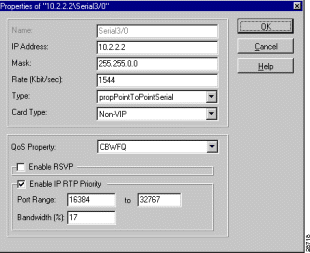
(a). Right-click the 10.2.2.2/Serial3/0 interface and select Interface Properties.
(b). In the Properties of Interface window, select Enable IP RTP Priority. The group expands to display the IP RTP Priority settings.
(c). Enter 16384 to 32767 for the port range. This is the entire port range used for voice traffic. By selecting this range, you ensure that all voice calls are placed in the IP RTP Priority queue.
(d). Enter 17 for bandwidth. This allocates up to 17% of the interface's bandwidth to voice traffic. To determine the percentage, estimate the number of concurrent calls that need to be supported on the interface, and multiply by the maximum rate required per voice call. Voice calls typically require 24 Kbps, but due to headers this can increase to 25 Kbps, so we suggest using 25 Kbps as the multiplier. Thus, 10 concurrent calls would require 250 Kbps. 250 Kbps is 16.2% of a T1 line's 1544 Kbps rate. Although we could enter 16.2 for the IP RTP Priority rate, we will round up to 17%.
It is important to understand that the IP RTP Priority queue bandwidth is considered part of the CBWFQ queues on CBWFQ interfaces. Normally, the combined queue bandwidth can be a maximum of 75%. On the 10.2.2.2/Serial3/0 interface, the existing CBWFQ queues comprise 50% of the interface, so adding the IP RTP Priority queue means we are allocating 67% of the interface's bandwidth to these 3 queues. However, these are not reserved queues—if a queue is not fully using its bandwidth, the bandwidth is available to other queues.
In addition to the percentage limitation, the IP RTP Priority queue cannot be larger than 2000 Kbps. (You can change the maximum allocatable bandwidth percentage using IOS software commands.)
Figure 3-22 shows the completed properties for this interface.
(e). Use a similar procedure to implement IP RTP Priority on the EdgeGroupOutbound and Remote device groups. The only difference is that you make the changes in the device group properties rather than the interface properties (right-click the device group and select Device Group Properties).
Step 5 Click the Save button, or select File>Save, to save your changes.
Step 6 Distribute your policies to the network.
(a). Click the Distribution Manager button, or select Tools>Distribution Manager, to start Distribution Manager.
(b). In Distribution Manager, select Devices>Create Job to create a distribution job from the Tutorial database.
QPM opens the Create Job window.
QPM creates a distribution job based on the policy definitions in the selected database. The job consists of the commands required to reconfigure the devices to implement your policies. Only the changes made since you last distributed the database are included in the job.
When you select the job, QPM displays the contents of the job in the list view, which shows the devices whose configurations will be changed by the job. If you double-click the device name in the list view, QPM displays the commands that will be sent to the device when you apply the job (the device must be available on the network).
QPM starts applying the changes defined in the job to the network devices. You can view the results of the jobs in the logs displayed in the bottom pane of Distribution Manager.
This lesson will teach you how to configure Frame Relay traffic shaping (FRTS) on Cisco routers. FRTS is frequently used to throttle traffic to the rate agreed upon with your WAN service provider, particularly if the destination link is running at a lower bandwidth than the source link.
For example, you might have a T1 line running at 1544 Kbps, but your service provider is committing to provide only 512 Kbps, and the destination of your traffic is a link running lower bandwidth than 1544 Kbps. By throttling the traffic rate at the source, you ensure that the traffic does not overwhelm the WAN link, resulting in dropped packets and increased delay. With FRTS, you can control the rate and smooth the traffic flow.
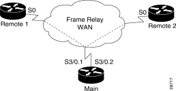
In this example, we will use a different network setup than used in previous lessons. Figure 3-23 shows three routers connected over a WAN cloud. All links are T1 Frame Relay lines. The Main router uses subinterfaces to enable routing between the two remote offices, Remote1 and Remote2. Most WAN traffic originates from the main office, so we will implement FRTS on the subinterfaces on the Main router. The service provider has committed to 512 Kbps for the Main-Remote1 link, and 256 Kbps for the Main-Remote2 link. There is no rate commitment for the interfaces on the remote links.
At the end of this lesson, you should be able to
If you want to create a policy and deploy it on a device that exists in your network, obtain the IP address of an appropriate device. Otherwise, you can use the IP addresses in this lesson so that you can follow these steps without affecting your network.
This lesson assumes that you have completed the steps in "Lesson 8—Upgrading CQ to CBWFQ and Implementing IP RTP Priority for Voice" section. Although you will not use the same network setup, you should already be familiar with adding devices and interfaces to the QoS database.
Table 3-5 lists the device details for this example. Because Remote1 and Remote2 links do not have a committed information rate, we are not enabling FRTS or other QoS capabilities on them in this example. Only add Main, its Serial3/0 interface, and its subinterfaces to the database.
Table 3-5 Technical Network Details for FRTS Lesson
|
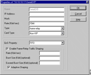
Step 2 Enable FRTS on the Main router's Serial3/0 interface. You must enable FRTS on an interface in order to configure FRTS on the interface's subinterfaces:
QPM opens the Properties of Interface window.
(b). Select FIFO for QoS Property. You must select a QoS Property other than "Do Not Change" if you want to configure interface QoS capabilities such as FRTS.
(c). Select Enable Frame Relay Traffic Shaping, but do not enter any rate or burst size information. The rates will be configured on the subinterfaces.
(d). Select Adaptive Shaping. This allows the interface to respond to notifications of congestion from the Remote1 and Remote2 routers, and throttle traffic accordingly.
Figure 3-24 shows the completed interface properties. Click OK when finished.
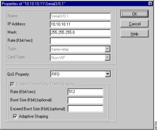
Step 3 Enable FRTS on the Main router's Serial3/0.1 interface:
Figure 3-25 shows the completed interface properties. Click OK when finished.
Step 4 Use the same procedure to enable FRTS on the Serial3/0.2 interface, making these interface selections:
Step 5 Click the Save button, or select File>Save, to save your changes.
Step 6 Distribute your policies to the network.
(a). Click the Distribution Manager button, or select Tools>Distribution Manager, to start Distribution Manager.
(b). In Distribution Manager, select Devices>Create Job to create a distribution job from the Tutorial database.
QPM opens the Create Job window.
QPM creates a distribution job based on the policy definitions in the selected database. The job consists of the commands required to reconfigure the devices to implement your policies. Only the changes made since you last distributed the database are included in the job.
When you select the job, QPM displays the contents of the job in the list view, which shows the devices whose configurations will be changed by the job. If you double-click the device name in the list view, QPM displays the commands that will be sent to the device when you apply the job (the device must be available on the network).
QPM starts applying the changes defined in the job to the network devices. You can view the results of the jobs in the logs displayed in the bottom pane of Distribution Manager.
![]()
![]()
![]()
![]()
![]()
![]()
![]()
![]()
Posted: Mon Aug 18 10:26:15 PDT 2003
All contents are Copyright © 1992--2003 Cisco Systems, Inc. All rights reserved.
Important Notices and Privacy Statement.


 Click the Apply button, or select Devices>Apply.
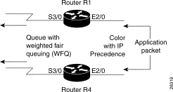
 Click the Application Services button, or select Tools>Application Services.
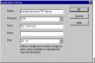
 Click the Host Groups button, or select Tools>Host Groups.