|
|

You can use ISM to monitor the availability of Cisco TN3270 servers, which reside on the Channel Interface Processors (CIPs) and channel port adapters of Cisco Routers. ISM monitors a TN3270 server using either SNMP or the service point in the router.
When you monitor TN3270 servers, keep the following considerations in mind:
Use the following procedures to monitor Cisco TN3270 servers:
Use the following procedure to enable ISM to monitor TN3270 servers:
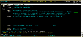
The ISM Administration menu panel (Figure 8-2) is displayed.

Step 2 Press Enter to display the ISM Resource Management Setup panel (Figure 8-3).

Step 3 Beside the TN3270 Server Monitor option, type Y in the Update column. Yes appears beside the TN3270 Server Monitor option. When you save the setup, the following line is added to the ISM main menu:
+ TN32 Cisco TN3270 Monitoring Operations
Step 4 To enable global TN3270 variables, type Y in the setup field of the TN3270 Server Monitor line and press Enter. The TN3270 Server Monitor Setup panel (Figure 8-4) is displayed.

The TN3270 Server Monitor Setup panel contains the following fields:
| Field | Description |
|---|---|
ISM TN3270 Server Monitoring | Indicates whether you have saved the ISM setup parameters. The default value is NO. This field is set to YES when you save the ISM setup parameters. |
TN3270 LU Threshold | Indicates a percentage of available LUs. ISM generates an alarm when the available LUs in a TN320 server drops below this percentage. The default value is 10 percent. |
TN3270 Response Threshold | This field is not supported. |
TN3270 Archive Data Base | Accept the default value of H unless you want to allocate another database and start a new NSPDS task. |
TN3270 Archive Keep Count | Indicates the archive keep count used by the TN3270 history record key. The default value is 99. If you do not use the default value, you must delete the existing history records before ISM uses the new value. |
TN3270 SMF Logging | Indicates whether SMF recording is enabled. The default value is YES. |
TN3270 Archive Logging | Indicates whether ISM is to archive the data it collects. The default value is YES. |
TN3270 Monitor Mode | If both SNA and SNMP can access the router, this field indicates whether ISM uses SNA or SNMP to monitor TN3270 servers. The default value is SNA. |
Step 5 Press PF4 to save your changes. If you have already initialized ISM, the changes are effective immediately.
You can monitor the status of TN3270 servers using either the standard interface or by the NetView Web interface. This section describes how to use the standard interface to perform the following tasks:
For details on using the Web interface, see the "Monitoring TN3270 Servers Using the Web Interface" section.
This section describes how to monitor the status of TN3270 servers using the standard interface.
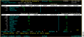
You can monitor the status of TN3270 servers from the ISM Status Summary panel or from the ISM main menu panel. The following steps show you how to access TN3270 Server Status from the ISM Status Summary panel:
The Cisco TN3270 Servers panel (Figure 8-6) is displayed.
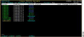
The Cisco TN3270 Servers panel displays the following fields:
| Field | Description |
|---|---|
Router | Router name with which this TN3270 server is associated. |
Channel | Channel interface on the router used by this TN3270 server. |
TN3270 Status | Current TN3270 server status. |
Last Change | Date and time of the last status change for this TN3270 server. |
Previous | Previous TN3270 server status. |
Step 2 To select options for TN3270 server operations, position the cursor on the selected router and press Enter. The ISM TN3270 Operation Options panel (Figure 8-7) is displayed, showing the TN3270 status and management options available for the TN3270.

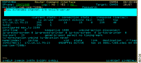
Step 3 To show detailed information for the channel used by the TN3270 server, select the Show Interface option. The interface information displays differently depending on whether the router has an SNA interface or an SNMP interface. If the router has an SNA interface, the Router Command Interface panel (Figure 8-8 ) is displayed.
If the router has an SNMP interface, the Interface Table panel (Figure 8-9 ) is displayed.
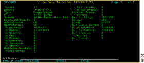
Step 4 To display the internal variables used by ISM to monitor the TN3270 server, select the Display Interface Variables option. Figure 8-10 and Figure 8-11 show the resulting output.


Step 5 To display the statistics that ISM has archived for a specific TN3270 server, select the History option. Figure 8-12 shows sample TN3270 history statistics.
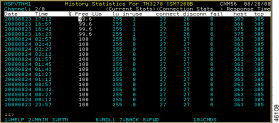
The TN3270 History Statistics panel displays the following fields:
| Field | Description |
|---|---|
Date | Date the statistics were archived. |
Time | Time the statistics were archived. |
% Free LUs | Percentage of LUs that are free. |
LU | Number of LUs defined for all PUs. |
In-Use | Number of of LUs in use. |
Connect | Number of connections made to this TN3270 server. |
Disconn | Number of disconnects from this TN3270 server. |
Fail | Number of connect failures for this TN3270 server. |
Host | Host response time (in milliseconds). |
TCP | TCP response time (in milliseconds). |
Step 6 If the router has an SNA interface, you can select the TN3270 Commands option, which enables you to issue show commands for TN3270 functions. Figure 8-13 shows the TN3270 Show Commands panel.
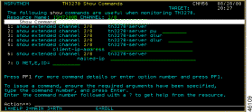
Step 7 Enter a number in the Action field and press Enter. Figure 8-14 shows an example of the panel that is displayed after 1 is entered in the Action field.
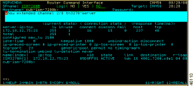
Step 8 To perform administrative tasks, select the Administration option. (This option is displayed only if you have the authority to change the management rules for monitoring routers.) The ISM Interface Administration panel (Figure 8-15) is displayed.

From the ISM Interface Administration panel, you can perform the following tasks:
Step 9 To reset TN3270 status from ALERT to ACTIV state, select the Reset option. (This option is displayed only if you have the authority to change the management rules for monitoring routers.) If the TN3270 server is available, ISM changes the status to ACTIV and issues status collection commands.
Step 10 To display TN3270 status via SNMP, select the Show Via SNMP option. (This option is displayed only if the router can be contacted using SNMP.) Selecting this option generates two panels of information. To see the second panel, press PF11. Figure 8-16 and Figure 8-17 show sample output from this option.
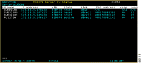
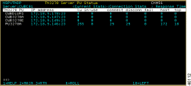
The TN3270 History Statistics panels display the following variables:
| Variable | Description |
|---|---|
PU Name | Name of this PU. |
IP Address | IP address and TCP port of this TN3270 server PU. |
XID | XID or ID block/ID number for this PU. |
State | Current state of this PU. |
Link | Indicates whether the connection to the host is via DLUR or via direct link. If via DLUR, the MAC, RSAP, and LSAP variables are undefined. |
MAC Address | (Direct link only) MAC address of the remote node. |
RSAP | (Direct link only) SAP address of the remote node. |
LSAP | (Direct link only) SAP address of the local direct node. |
TN3270 PU | Name of this PU. |
IP Address | IP address and TCP port of this TN3270 server PU. |
LU | Number of TN3270 sessions configured that are available for use by TN3270 clients. |
In-Use | Number of sessions in use. |
Connects | Total number of TN3270 sessions connected. |
Disconn | Total number of TN3270 sessions disconnected. |
Fail | Total number of attempted sessions that failed to negotiate TN3270/E, or that were rejected by the control point. |
Host | Response time for all sampled inbound transactions for which response time is computed. Response time is the interval between the time the EOR was received from the client and the time the reply was received from the host. |
TCP | If the timing mark is configured, response time is computed for all sampled timing marks on which response time is computed. Response time is the interval between the time the timing mark was sent to the client and the time the reply was received from the client. |
Step 11 To display the status of the LUs associated with this PU, position the cursor on a TN3270 PU name and press Enter. Figure 8-18 shows sample output for this selection.
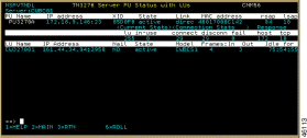
The TN3270 Server PU Status with LUs panel contains the following LU output fields:
| Field | Description |
|---|---|
LU Name | Name of this LU. |
IP Address | IP address and TCP port of the TN3270 client connected to this LU. |
Nail | Indicates whether this LU has been configured for a specific TN3270 client (nailed). |
State | Current state of the LU. |
Model | Terminal type or model number of the incoming TN3270 client. |
Frames In | Number of RUs sent by the local LU. |
Frames Out | Number of RUs received by the local LU. |
Idle For | Time since last activity was recorded on this LU. |
You can monitor TN3270 server operations from the ISM main menu (Figure 8-1). To do so, use the following procedure:
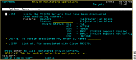
The TN3270 Monitoring Operations panel provides the following options:
| Option | Description |
|---|---|
LIST:Filter:Router | Select this option and enter a router name to list TN3270 servers by router name. If you do not enter a router name, all TN3270 routers are displayed. |
LIST:Filter:Status | Select this option and select a status to list TN3270 servers by their current status. By default, this option lists all channels that are TN3270 server-capable, except those that are in NOMON state. If you do not enter a status, all TN3270 routers are displayed. |
LOCATE | (Local VTAM-managed LUs only) Enter an LU name to list the associated TN3270 PUs. |
LISTP | List all TN3270 PUs. |
Figure 8-20 shows sample output for the List by Status option.
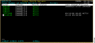
Step 2 To find the TN3270 server PU that an LU is using, enter the LU's name in the TN3270 Monitoring Operations menu (Figure 8-19) and press Enter. The TN3270 Show Commands panel (Figure 8-21) is displayed, showing any associated TN3270 PUs.
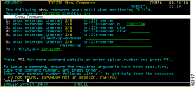
Step 3 To help with problem determination, enter option 1, 2, or 7.
Figure 8-22 shows sample output if you enter a 2 in the Action field, thereby issuing the show extended channel 2/0 tn3270-server pu ISM3270A command.
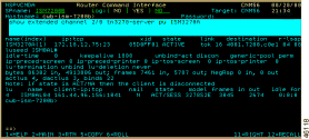
Figure 8-23 shows sample output if you enter a 7 in the Action field.
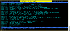
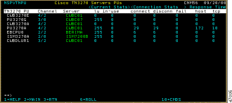
Step 4 To display all PUs associated with Cisco TN3270 servers, select option LISTP. A list of all TN3270 PUs (Figure 8-24) is displayed.
You can monitor the status of TN3270 servers using either the standard interface or by the NetView Web interface. This section describes how to use the Web interface to perform the following tasks:
To monitor the status of TN3270 servers using the NetView Web interface, complete the following steps:
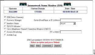
The ISM Status Summary page (Figure 8-26) is displayed.
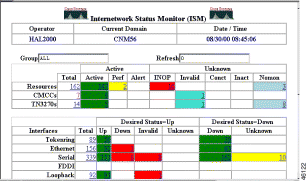
Step 2 Select a field in the CMCCs row. The Cisco TN3270 Servers page (Figure 8-27) is displayed.
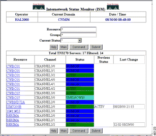
The Cisco TN3270 Servers page contains the following fields:
| Field | Description |
|---|---|
Resource | Router name with which this TN3270 server is associated. |
Channel | Channel interface on the router used by this TN3270 server. |
Status | Current TN3270 server status. |
Previous Status | Previous TN3270 server status. |
Last Change | Date and time of the last status change for this TN3270 server. |
Step 3 Select a router to display its TN3270 options. The ISM TN3270 Operation Options page (Figure 8-28) is displayed, which shows the TN3270 status and management options available for the TN3270 server.

Step 4 To issue show commands for TN3270 functions, select Show Commands. (This option is displayed only if the router has an SNA interface.) The TN3270 Show Commands page (Figure 8-29) is displayed.

Step 5 To show the available commands for a given PU name, enter the PU name and click Submit. You can then select a command for that PU name. ISM prompts you if other input is required.
Figure 8-30 shows sample output for the first command in the list.

Step 6 To show the internal variables used by ISM to monitor the TN3270 server, on the ISM TN3270 Operation Options page (Figure 8-28), click Display Interface Variables. Figure 8-31 shows sample output for this option.
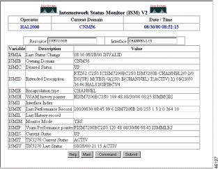
Step 7 To display the statistics that ISM has archived for the selected TN3270 server, on the ISM TN3270 Operation Options page (Figure 8-28), click History. The TN3270 History page (Figure 8-32 ) is displayed.

The TN3270 History page displays the following fields:
| Field | Description |
|---|---|
Date | Date the statistics were archived. |
Time | Time the statistics were archived. |
% Free LUs | Percentage of LUs that are free. |
LU's | Number of LUs defined for all PUs. |
In Use | Number of of LUs in use. |
Connect | Number of connections made to this TN3270 server. |
DisConn | Number of disconnects from this TN3270 server. |
Fail | Number of connect failures for this TN3270 server. |
Host | Host response time (in milliseconds). |
TCP | TCP response time (in milliseconds). |
Step 8 To display TN3270 status via SNMP, on the ISM TN3270 Operation Options page (Figure 8-28), click Show Via SNMP. (This option is displayed only if the router can be contacted using SNMP.) The ISM TN3270 Server PU Status page (Figure 8-33) is displayed.

The TN3270 Server PU Status page contains the following variables:
| Variable | Description |
|---|---|
PU Name | Name of this PU. If the PU name is a hyperlink, select it to display LU statistics associated with this PU. |
IP Address | IP address and TCP port of this TN3270 server PU. |
XID | XID or ID block/ID number for this PU. |
State | Current state of this PU. |
Link | Indicates whether the connection to the host is via DLUR or via direct link. If via DLUR, the MAC, RSAP, and LSAP variables are undefined. |
MAC Address | (Direct link only) MAC address of the remote node. |
RSAP | (Direct link only) SAP address of the remote node. |
LSAP | (Direct link only) SAP address of the local direct node. |
LU | Number of TN3270 sessions configured that are available for use by TN3270 clients. |
In Use | Number of sessions in use. |
Connect | Total number of TN3270 sessions connected. |
DisConn | Total number of TN3270 sessions disconnected. |
Fail | Total number of attempted sessions that failed to negotiate, or that were rejected by the control point. |
Host | Response time (in milliseconds) for all sampled inbound transactions for which response time is computed. Response time is the interval between the time the EOR was received from the client and the time the reply was received from the host. |
TCP | If the timing mark is configured, response time (in milliseconds) for all sampled timing marks on which response time is computed. Response time is the interval between the time the timing mark was sent to the client and the time the reply was received from the client. |
Select a TN3270 PU name to display the status of the LUs associated with this PU, as shown in Figure 8-34.

The ISM TN3270 Server PU Status with LUs page contains the following LU output fields:
| Field | Description |
|---|---|
LU Name | Name of this LU. |
IP Address | IP address and TCP port of the TN3270 client connected to this LU. |
Nail | Indicates whether this LU has been configured for a specific TN3270 client (nailed). |
State | Current state of the LU. |
Model | Terminal type or model number of the incoming TN3270 client. |
Frames In | Number of RUs sent by the local LU. |
Frames Out | Number of RUs received by the local LU. |
Idle For | Time since last activity was recorded on this LU. |
To monitor TN3270 server operations, use the following procedure:

The TN3270 Monitor Operations page provides the following options:
| Option | Description |
|---|---|
List by Resource | Select this option, enter a router name, and click Submit to list TN3270 servers by router name. If you do not enter a router name, all TN3270 routers are displayed. |
List by Status | Select this option, select a status, and click Submit to list TN3270 servers by their current status. By default, this option lists all channels that are TN3270 server-capable, except those that are in NOMON state. If you do not enter a status, all TN3270 routers are displayed. |
Locate PU by Given LU Name | (Local VTAM-managed LUs only) Select this option, enter an LU name, and click Submit to list the associated TN3270 PUs. |
List All PUs | Select this option, and click Submit to list all TN3270 PUs. |
Figure 8-36 shows sample output for the List by Status option.
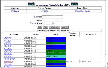
Step 2 To display all PUs associated with Cisco TN3270 servers, on the TN3270 Monitor Operations page (Figure 8-35), select List All PUs and click Submit. A list of all TN3270 PUs (Figure 8-37) is displayed.
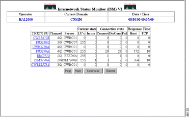
Step 3 To find the TN3270 server PU that is associated with an LU, on the TN3270 Monitor Operations page (Figure 8-35), select Locate PU by Given LU Name, enter the LU's name, and click Submit. Figure 8-38 shows sample output for locating an LU.

Step 4 To help with problem determination, click on a command.
Figure 8-39 shows sample output for the show extended channel 2/0 tn3270-server pu ISM3270A command.
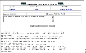
Figure 8-40 shows sample output for the d net,e,id=ISM3270A command, which displays VTAM information about the specified PU.

![]()
![]()
![]()
![]()
![]()
![]()
![]()
![]()
Posted: Sat Oct 7 16:24:42 PDT 2000
Copyright 1989-2000©Cisco Systems Inc.