|
|

Table Of Contents
Setting Up Devices for IOS XR Support
Creating Customers, Sites, and CPEs
Creating Providers, Regions, and PEs
Creating a Route Distinguisher Pool
Creating a Site of Origin Pool
Enabling a Unique Route Distinguisher for a VPN
Creating CE Routing Communities
Setting Up the ISC Services
This chapter contains the basic steps to set up the Cisco IP Solution Center (ISC) services to support MPLS VPN service policies and service requests. It contains the following sections:
•
Overview
•
•
•
Note
Overview
To create an MPLS VPN service request, you must create the following infrastructure data:
•
A Device in ISC is a logical representation of a physical device in the network. You can import devices (configurations) into ISC by using Inventory Manager or the ISC GUI. You can also use the Auto Discovery feature of Inventory Manager to import devices into the Repository.
•
A customer is typically an enterprise or large corporation that receives network services from a service provider. A Customer is also a key logical component of ISC.
–
A Site is a logical component of ISC that connects a Customer with a CE. It can also represent a physical customer site.
–
A CPE is "customer premises equipment," typically a customer edge router (CE). It is also a logical component of ISC. You can create CPE in ISC by associating a device with a Customer Site.
•
A provider is typically a "service provider" or large corporation that provides network services to a customer. A Provider is also a key logical component of ISC.
–
A Region is a logical component of ISC that connects a Provider with a PE. It can also represent a physical provider region.
–
A PE is a provider edge router or switch. It is also a logical component of ISC. You can create PE in ISC by associating a Device with a Provider Region. In ISC, a PE can be a "point of presence" router (POP) or a Layer 2 switch (CLE).
•
The Layer 2 Ethernet switching domain that connects a PE to a CE is called an Access Domain. All the switches attached to the PE-POP belong to this Access Domain. These switches belong to the Provider and are defined in ISC as PE-CLE.
•
–
–
–
–
–
•
Before creating a Service Policy, a VPN name must be defined within ISC.
•
Creating Devices
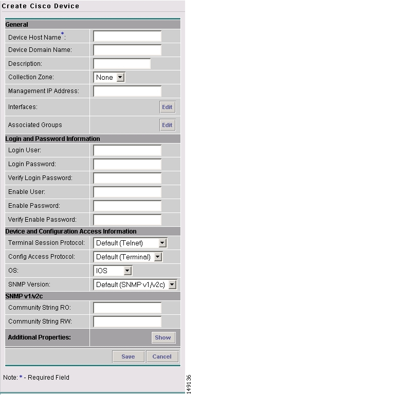
This section describes how to create a Device with the ISC GUI, connect to a Cisco IOS router in the network, collect the live configuration, and populate the Repository. This section covers the following topics:
•
Creating Logical Devices
To create a logical device, perform the following steps:
Step 1
The Devices window appears.
Step 2
Step 3
The Create Cisco Device window appears, as shown in Figure 2-1.
Figure 2-1 New Device Information
Step 4
Step 5
Step 6
You have saved a Device in the Repository.
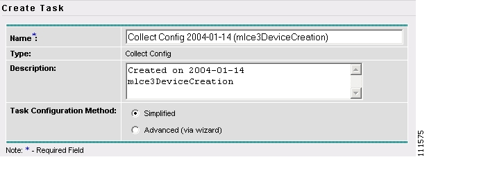
Collecting Configurations
This section describes how to connect to the physical device in the network, collect the device information from the router, and populate the Repository. To do this, perform the following steps:
Step 1
The Tasks window appears.
Step 2
Step 3
The Create Task window appears, as shown in Figure 2-2.
Tip
Figure 2-2 Create Task
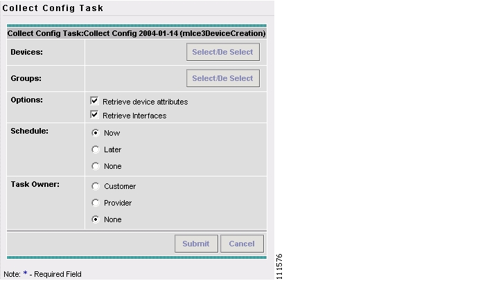
Step 4
The Collect Config Task window appears, as shown in Figure 2-3.
Figure 2-3 Collect Config Task
Step 5
The Select Device window appears.
Step 6
The Collect Config Task window reappears.
Step 7
A list of available device groups appears.
Step 8
The Collect Config Task window reappears.
Step 9
Step 10
The Tasks window appears.
Step 11
Monitoring Task Logs
To monitor task logs, perform the following steps:
Step 1
The Tasks window appears.
Step 2
The Task Runtime Actions window appears.
Note
Step 3
Creating Device Groups
To create device groups, perform the following steps:
Step 1
The Device Groups window appears.
Step 2
The Create Device Group window appears.
Step 3
Step 4
Setting Up Devices for IOS XR Support
ISC 5.0.1 supports provisioning of basic MPLS VPNs on devices running Cisco's IOS XR software. IOS XR, a new member of the Cisco IOS family, is a unique self-healing and self-defending operating system designed for always-on operation while scaling system capacity up to 92Tbps.
Note
To enable IOS XR support in MPLS VPN, perform the following steps:
Step 1
Possible values are CLI, CLI_XML, and XML (the default).
Step 2
This allows ISC to retrieve the committed CLI configuration after an XML configuration has been downloaded. See Viewing Configlets on IOS XR Devices for more information.
Step 3
a.
The Create Cisco Device window appears.
b.
Note
Step 4
Sample configlets for IOS XR devices are provided in Appendix A, "Sample Configlets".
Creating Customers, Sites, and CPEs
In ISC, a customer is defined by the following three logical components:
•
•
•
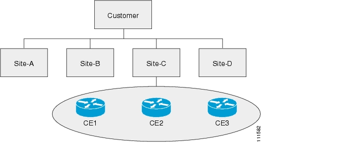
In ISC, a Customer is a logical container for Sites and CEs.
Within a Customer, there can be one or more Sites. Sites are logical entities that can be defined in any way that makes sense to a service provider.
Figure 2-4 shows an overview of an ISC Customer.
Figure 2-4 Overview of an ISC Customer
This section describes how to create a Customer with the ISC GUI, create a Site for the Customer, and associate a Device with the Site. This section covers the following topics:
Creating Customers
To create a customer, perform the following steps:
Step 1
The Customers window appears.
Step 2
The Create Customer window appears.
Step 3
The Customers window appears.
Creating Sites
To create a site, perform the following steps:
Step 1
Step 2
The Customer Site window appears.
Step 3
The Create Customer Site window appears.
Step 4
Step 5
A list of available customer names appears.
Step 6
The Create Customer Site window reappears.
Step 7
Creating CPEs
To create a CPE device, perform the following steps:
Step 1
Step 2
The CPE Devices window appears.
Step 3
The Create CPE Device window appears.
Step 4
The Select Device window appears.
Step 5
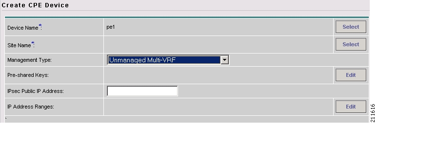
The Create CPE Device window reappears, as shown in Figure 2-5.
Figure 2-5 Create CPE Device
Step 6
Step 7
The Create CPE Device window appears showing the Unmanaged Multi-VRF CPE Device you have created.
Creating Providers, Regions, and PEs
In ISC, a Provider is defined by the following three logical components:
•
•
•
In ISC, a provider administrative domain (PAD) is a single AS. It is not a specific service provider, rather it is a logical container for Regions and PEs.
Within a single PAD, there must be one or more Regions. Regions are logical entities that can be defined in any way that makes sense to a service provider.
Within a Region, a Provider can contain one or more PEs. The PEs can be a PE-POP ("router") or a PE-CLE ("switch").
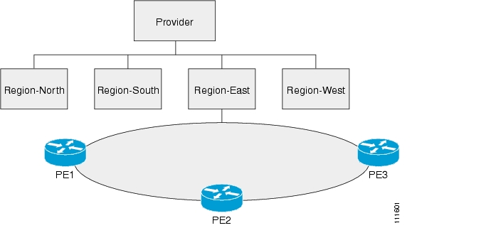
Figure 2-6 shows an overview of an ISC Provider.
Figure 2-6 Overview of an ISC Provider
This section covers the following topics:
Creating a Provider
To create a provider, perform the following steps:
Step 1
The Providers window appears.
Step 2
The Create Provides window appears.
Step 3
Step 4
Step 5
Step 6
Creating a Region for PE
To create a region, perform the following steps:
Step 1
The Provider Regions window appears.
Step 2
The Create Provider Region window appears.
Step 3
Step 4
Step 5
Creating PEs
To set up a device as a Provider Edge (PE) device, perform the following steps:
Step 1
Step 2
The PE Devices window appears.
Step 3
The Create PE Device window appears.
Step 4
The Select Device window appears.
Step 5
The Create PE Device window reappears, as shown in Figure 2-7.
Figure 2-7 Create PE Device
Step 6
The Select Region window appears.
Step 7
The Create PE Device window reappears.
Step 8
Note
Step 9
The PE Device window appears showing the PE device you have created.
Editing PEs
To view or edit a PE, perform the following steps:
Step 1
Step 2
The PE Devices window appears.
Step 3
Step 4
The Edit PE Device window appears.
Step 5
Creating Access Domains
Note
Any Transport over MPLS (AToM) is the Cisco solution for transporting Layer 2 traffic over an IP/MPLS backbone. AToM is required for supporting legacy services over MPLS infrastructures and for supporting new connectivity options, including Layer 2 VPNs and Layer 2 virtual leased lines.
AToM supports three types of Ethernet-based L2VPNs (EoMPLS):
•
•
•
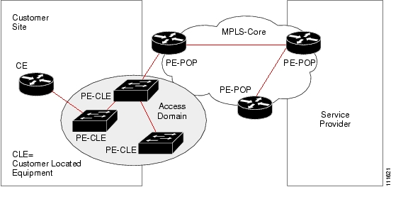
The Layer 2 Ethernet switching domain that connects a PE to a CE is called an Access Domain. All the switches attached to the PE-POP belong to this Access Domain. These switches belong to the Provider and are defined in ISC as PE-CLE.
Note
ISC supports multiple PE-POPs per Access Domain and multiple PE-CLE devices can be included. Figure 2-8 shows an overview of an ISC Access Domain.
Figure 2-8 Overview of an Access Domain
To create an Access Domain, perform the following steps:
Step 1
Step 2
The Access Domains window appears.
Step 3
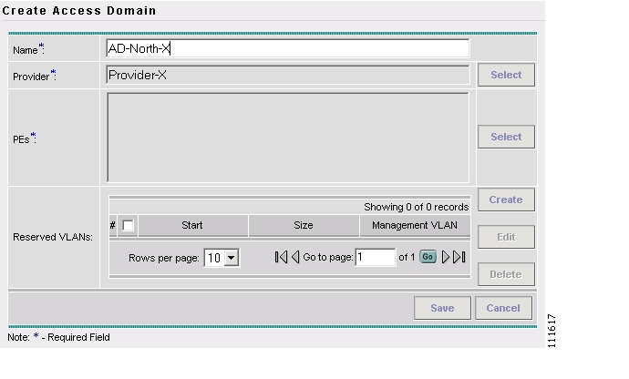
The Create Access Domain window appears, as shown in Figure 2-9.
Figure 2-9 Create Access Domain
Step 4
Step 5
Step 6
The Show PEs window appears.
Step 7
Step 8
You are returned to the Create Access Domain window.
Step 9
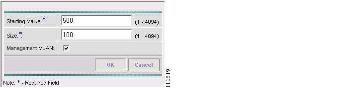
The Create Reserved VLAN window appears, as shown in Figure 2-10.
Figure 2-10 Create Reserved VLAN
Step 10
Step 11
Step 12
Step 13
The Access Domains window appears showing that the Access Domain has been saved in the Repository.
Creating Resource Pools
This section describes how to create Resource Pools using the Cisco IP Solution Center (ISC) GUI. It contains the following sections:
•
•
•
•
Overview of Resource Pools
Before creating a service in ISC, you must define your Resource Pools. From these Resource Pools, ISC can automatically assign some values during the provisioning process. You can also manually assign these values during the provisioning process, but it is not recommended.
ISC allocates numbers from the following pools during the provisioning process:
•
•
•
•
•
•
•
Creating an IPv4 Address Pool
To create an IPv4 address pool, perform the following steps:
Step 1
The Resource Pools window appears.
Step 2
Step 3
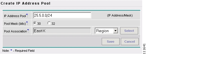
The Create IP Address Pool window appears, as shown in Figure 2-11.
Figure 2-11 Create IP Address Pool
Step 4
Step 5
Note
Step 6
The Select Region window appears.
Step 7
Step 8
The Create IP Address Pool window reappears.
Step 9
The Resource Pools - IP Address window appears showing that the IP Address Pool is in the Repository.
Creating a Multicast Pool
To create a multicast pool, perform the following steps:
Step 1
The Resource Pools window appears.
Step 2
The Resource Pools - Multicast window appears.
Step 3
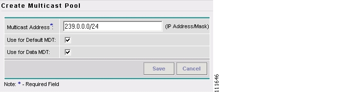
The Create Multicast Pool window appears, as shown in Figure 2-12.
Figure 2-12 Create Multicast Pool
Step 4
Step 5
Step 6
The Resource Pools - Multicast window appears showing the Multicast Address Pool in the Repository.
Creating a Route Distinguisher Pool
To create a route distinguisher (RD) pool, perform the following steps:
Step 1
The Resource Pools window appears.
Step 2
The Resource Pools - Route Distinguisher window appears.
Step 3
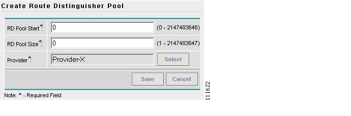
The Create Route Distinguisher Pool window appears, as shown in Figure 2-13.
Figure 2-13 Create Route Distinguisher Pool
Step 4
Step 5
Step 6
The Select Provider window appears.
Step 7
Step 8
The Create Route Distinguisher Pool window reappears.
Step 9
The Resource Pools - Route Distinguisher window appears showing the Route Distinguisher Pool in the Repository.
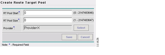
Creating a Route Target Pool
To create a route target (RT) pool, perform the following steps:
Step 1
The Resource Pools window appears.
Step 2
The Resource Pools - Route Target window appears.
Step 3
The Create Route Target Pool window appears, as shown in Figure 2-14.
Figure 2-14 Create Route Target Pool
Step 4
Step 5
Step 6
The Select Provider window appears.
Step 7
Step 8
The Create Route Target Pool window reappears.
Step 9
The Resource Pools - Route Target window appears showing the Route Target Pool in the Repository.
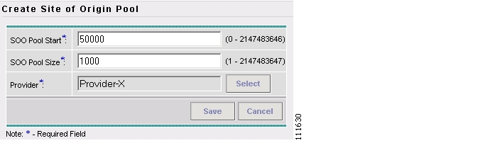
Creating a Site of Origin Pool
To create a site of origin (SOO) pool, perform the following steps:
Step 1
The Resource Pools window appears.
Step 2
The Resource Pools - Site of Origin window appears.
Step 3
The Create Site of Origin Pool window appears, as shown in Figure 2-15.
Figure 2-15 Create Site of Origin Pool
Step 4
Step 5
Step 6
The Select Provider window appears.
Step 7
Step 8
The Create Site of Origin Pool window reappears.
Step 9
The Create Route Target Pool window appears showing a Site of Origin Pool in the Repository.
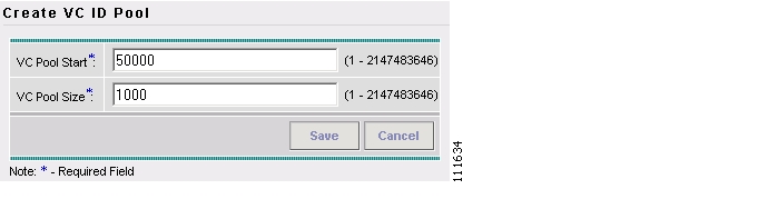
Creating a VC ID Pool
To create a VC ID pool, perform the following steps:
Step 1
The Resource Pools window appears.
Step 2
The Resource Pools - VC ID window appears.
Step 3
The Create VC ID Pool window appears, as shown in Figure 2-16.
Figure 2-16 Create VC ID Pool
Step 4
Step 5
Step 6
The Resource Pools - VC ID window appears showing a VC ID Pool in the Repository.
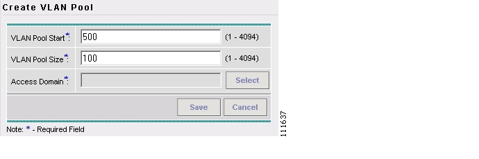
Creating a VLAN Pool
To create a VLAN pool, perform the following steps:
Step 1
The Resource Pools window appears.
Step 2
The Resource Pools - VLAN window appears.
Step 3
The Create VLAN Pool window appears, as shown in Figure 2-17.
Figure 2-17 VLAN Pool
Step 4
Step 5
Step 6
The Select Access Domain window appears.
Step 7
Step 8
The Create VLAN Pool window reappears.
Step 9
The Resource Pools - VLAN window appears showing the VLAN Pool in the Repository.
Defining VPNs
During service deployment, ISC generates the Cisco IOS commands to configure the logical VPN relationships. At the beginning of the provisioning process, before creating a Service Policy, a VPN can be defined within ISC.
Note
This section describes how to define MPLS VPNs and IP Multicast VPNs. It contains the following sections:
•
•
Creating an MPLS VPN
At its simplest, a virtual private network (VPN) is a collection of sites that share the same routing table. A VPN is also a framework that provides private IP networking over a public infrastructure such as the Internet. In Cisco IP Solution Center (ISC), a VPN is a set of customer sites that are configured to communicate through a VPN service. A VPN is defined by a set of administrative policies.
A VPN is a network in which two sites can communicate over the provider's network in a private manner; that is, no site outside the VPN can intercept their packets or inject new packets. The provider network is configured such that only one VPN's packets can be transmitted through that VPN—that is, no data can come in or out of the VPN unless it is specifically configured to allow it. There is a physical connection from the provider edge network to the customer edge network, so authentication in the conventional sense is not required.
To create an MPLS VPN, perform the following steps:
Step 1
Step 2
The Inventory and Connection Manager window appears.
Step 3
The VPNs window appears.
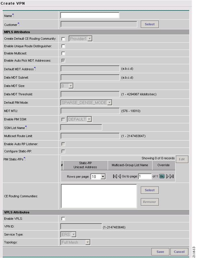
Step 4
The Create VPN window appears, as shown in Figure 2-18.
Figure 2-18 Create VPN
Step 5
Step 6
a.
The Select Customer dialog box appears.
b.
The Create VPN window reappears.
Step 7
Step 8
Step 9
Step 10
Note
a.
The Select CE Routing Communities dialog box appears.
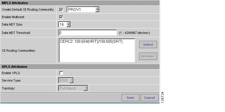
b.
You return to the Create VPN dialog box, where the new CERC selection appears, along with its hub route target (HRT) and spoke route target (SRT) values, as shown in Figure 2-19.
Figure 2-19 New CERC Selected
Step 11
Step 12
Step 13
Step 14
You have successfully created a VPN, as shown in the Status display in the lower left corner of the VPNs dialog box.
Creating an IP Multicast VPN
An IP address that starts with the binary prefix 1110 is identified as a multicast group address. There can be more than one sender and receiver at any time for a given multicast group address. The senders send their data by setting the group address as the destination IP address. It is the responsibility of the network to deliver this data to all the receivers in the network who are listening to that group address.
Note
Note
Note
To create an IP Multicast VPN, follow the procedure described in Creating an MPLS VPN to the place where you can enable multicast for the VPN, then perform the following steps:
Step 1
The current window refreshes with additional fields becoming active.
Step 2
•
•
Step 3
Step 4
Step 5
•
•
Tip
Note
Step 6
Note
Step 7
When you check the check box:
a.
Note
b.
Step 8
Step 9
Note
Step 10
Note
Step 11
When you check this, the Edit option for PIM Static RPs goes active.
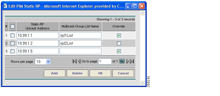
Step 12
The Edit PIM Static RPs window appears, as shown in Figure 2-20.
Figure 2-20 Edit PIM Static RPs
Step 13
The data now appears in the main Create VPN window.
Step 14
Enabling a Unique Route Distinguisher for a VPN
Support for multipath load sharing requires unique route distinguishers (RDs) for each PE router for a VPN (VRF). This is to prevent the same RDs from being allocated to different customers. This allows the use of the same RD for the same VRF. That is, all sites in the PE can have the same unique RD. The unique RD feature is optional. It is enabled at both a global VPN level or a service request level. To enable the unique RD per PE for a VPN, the Create VPN window contains the attribute Enable Unique Route Distinguisher field.
Each VPN deployed through ISC for which Enable Unique Route Distinguisher has been selected is marked as a multipath VPN. This ensures a unique RD allocation for each VRF on each PE. Enabling multipath for an already deployed VPN creates new VRFs on all the PEs of the VPN and assigns a unique RD. When Enable Unique Route Distinguisher is selected for the VPN, the Allocate New Route Distinguisher and VRF and RD Overwrite attributes will be disabled when setting up a policy or service request that uses this VPN.
To use the unique RD feature, perform the following steps:
Step 1
Step 2
The Unique Route Distinguisher field appears.
Step 3
For additional information on how this feature is used with MPLS VPN policies and service requests, see Defining VRF and VPN Information, page 5-29.
Creating CE Routing Communities
CE Routing Communities (CERCs) arehow ISC handles the Route Targets (RT) transparently from the users, and it can help the service providers to easily implement various kinds of VPN topology. When you create a VPN, the ISC software creates one default CE routing community (CERC) for you. But if your network topology and configuration require customized CERC definitions, you can define CERCs customized for your network.
Tip
To build complex topologies, it is necessary to break down the required connectivity between CEs into groups, where each group is either fully meshed, or has a hub-and-spoke pattern. A CE can be in more than one group at a time, so long as each group has one of the two basic configuration patterns.
Each subgroup in the VPN needs its own CERC. Any CE that is only in one group just joins the corresponding CERC (as a spoke if necessary). If a CE is in more than one group, then you can use the Advanced Setup choice during provisioning to add the CE to all the relevant groups in one service request. Given this information, ISC does the rest, assigning route target values and VRF tables to arrange the precise connectivity the customer requires.
To define a new CERC, perform the following steps:
Step 1
Step 2
The Inventory and Connection Manager window appears.
Step 3
The CE Routing Communities window appears.
Step 4
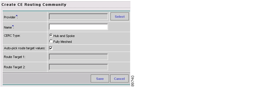
The Create CE Routing Community window appears, as shown in Figure 2-21.
Figure 2-21 Defining a New CE Routing Community
Step 5
a.
The Select Provider dialog box appears.
b.
c.
d.
e.
By default, the Auto-pick route target values check box is checked. If you uncheck the check box, you can enter the Route Target values manually.
Note
Step 6
![]()
![]()
![]()
![]()
![]()
![]()
![]()
![]()
Posted: Mon Feb 18 15:18:56 PST 2008
All contents are Copyright © 1992--2008 Cisco Systems, Inc. All rights reserved.
Important Notices and Privacy Statement.