|
|

Table Of Contents
Provisioning Multi-VRFCE PE-CE Links
MPLS VPN MVRFCE PE-CE Link Overview
Creating MPLS VPN MVRFCE PE-CE Service Policies
Creating MVRFCE PE-CE Service Policies
Creating PE-NoCE Service Policies
Creating MPLS VPN MVRFCE PE-CE Service Requests
Creating MVRFCE PE-CE Service Requests
Creating MVRFCE PE-NoCE Service Requests
Provisioning Multi-VRFCE PE-CE Links
This chapter describes how to configure MPLS VPN Multi-VRFCE PE-CE links in the IP Solution Center (ISC) provisioning process. It contains the following major sections:
•
MPLS VPN MVRFCE PE-CE Link Overview
•
•
•
MPLS VPN MVRFCE PE-CE Link Overview
This section contains the following sections:
To provision an MPLS VPN service in ISC, you must first create an MPLS VPN Service Policy. In ISC, a Service Policy is a set of default configurations for creating and deploying a Service Request.
ISC supports two MPLS VPN Service Policy Types: Regular PE-CE an MVRFCE PE-CE. The following scenarios focus on the MVRFCE PE-CE Policy Type.
An MVRFCE PE-CE Policy Type is a PE to CE link with three devices:
•
•
•
This Policy Type has two options:
•
•
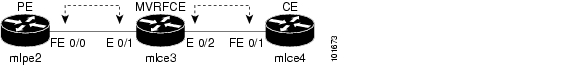
Figure 8-1 shows an example of an MVRFCE PE-CE link with three devices.
Figure 8-1 MVRFCE PE-CE Link
In an MVRFCE PE-CE link with CE Present enabled, interfaces FE 0/0, E 0/1, E 0/2 and FE 0/1 are configured as an MPLS VPN link in the Service Request process.
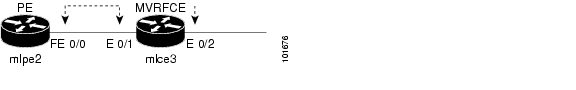
Figure 8-2 shows an example of a PE to MVRFCE link with no CE.
Figure 8-2 MVRFCE PE-CE Link with No CE
In an MVRFCE PE-CE link with CE Present disabled, interfaces FE 0/0, E 0/1, and E 0/2 are configured as an MPLS VPN link in the Service Request process.
Network Topology
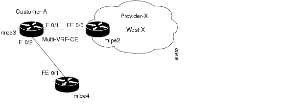
Figure 8-3 shows an overview of the network topology in which the MPLS VPN MVRFCE PE-CE links are created.
Figure 8-3 Network Topology for MPLS VPN MVRFCE PE-CE Scenarios
The network topology in Figure 8-3 illustrates the lab environment of a service provider (Provider-X) and one customer (Cust-A). There is one Region (West-X) and one PE (mlpe2.cisco.com). Each customer device (one MVRFCE and one CE) represents a Site (mlce3-Site and mlce4-Site).
Prerequisite Tasks
Before you can create a Service Policy in ISC, you must complete the following Inventory Management tasks:
Step 1
Step 2
Step 3
Step 4
Step 5
Step 6
Step 7
Step 8
Defining VPN for MVRFCE PE-CE Links
During service deployment, ISC generates the Cisco IOS commands to configure the logical VPN relationships.
At the beginning of the provisioning process, before creating a Service Policy, a VPN must be defined within ISC. The first element in a VPN definition is the name of the VPN.
To create a VPN Name, perform the following steps:
Step 1
The VPN window appears.
Step 2
The Create VPN window appears.
Step 3
•
•
The Select Customer window appears.
Step 4
Step 5
The VPNs window reappears showing that the VPN Name is associated to the Customer in this new VPN definition.
Creating MPLS VPN MVRFCE PE-CE Service Policies
This section contains the following sections:
•
•
Creating MVRFCE PE-CE Service Policies
To create an MVRFCE PE-CE service policy, perform the following steps:
Note
Step 1
The Policies window appears.
Step 2
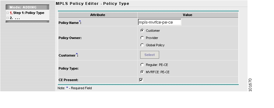
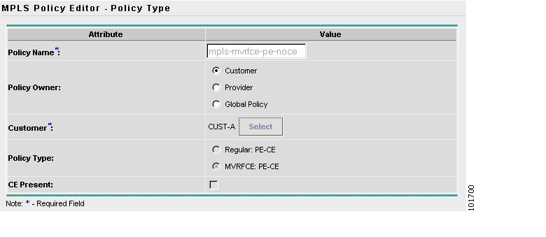
The MPLS Policy Editor - Policy Type window appears, as shown in Figure 8-4.
Figure 8-4 MPLS Policy Editor - Policy Type
Step 3
•
•
•
–
The Customer for MPLS Policy window appears.
–
•
•
Step 4
The MPLS Policy Editor - PE Interface window appears, as shown in Figure 8-5.
Figure 8-5 The MPLS Policy Editor - PE Interface
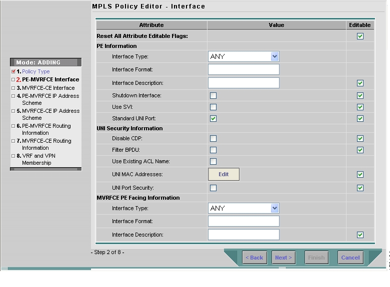
Step 5
The MPLS Policy Editor - Interface window appears.
Step 6
The MPLS Policy Editor - IP Address Scheme window appears for PE-MVRFCE.
Step 7
Step 8
Step 9
Step 10
The MPLS Policy Editor - Routing Information window appears for PE-MVRFCE.
Step 11
The MPLS Policy Editor - Routing Information window appears for MVRFCE-CE.
Step 12
The MPLS Policy Editor - VRF and VPN Membership window appears.
Step 13
The Policies window reappears showing that the MPLS VPN MVRFCE PE-CE Service Policy is complete.
Creating PE-NoCE Service Policies
To create a PE-NoCE service policy, perform the following steps:
Step 1
The Policies window appears.
Step 2
The MPLS Policy Editor - Policy Type window appears, as shown in Figure 8-6.
Figure 8-6 MPLS Policy Editor - Policy Type
Step 3
•
•
•
–
The Customer for MPLS Policy window appears.
–
•
•
Step 4
The MPLS Policy Editor - Interface window appears.
Step 5
The MPLS Policy Editor - Interface window appears for MVRFCE-CE Facing Information.
Step 6
The MPLS Policy Editor - IP Address Scheme window appears for PE-MVRFCE-CE Interface Address/Mask.
a.
b.
c.
d.
Step 7
The MPLS Policy Editor - IP Address Scheme window appears for MVRFCE-CE Interface Address/Mask.
a.
b.
c.
d.
Step 8
The MPLS Policy Editor - Routing Information window appears for PE-MVRFCE Routing Information.
Step 9
The MPLS Policy Editor - Routing Information window appears for MVRFCE-CE Routing Information.
Step 10
The MPLS Policy Editor - VRF and VPN Membership window appears.
Step 11
Step 12
The MPLS Policy Editor - VRF and VPN Membership window appears.
Step 13
The Policies window reappears showing that the MPLS VPN PE-NoCE Service Policy is complete.
Creating MPLS VPN MVRFCE PE-CE Service Requests
This section contains the following sections:
•
•
Creating MVRFCE PE-CE Service Requests
To create an MVRFCE PE-CE service request, perform the following steps:
Step 1
The Service Requests window appears.
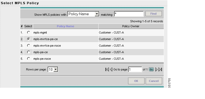
Step 2
The Select MPLS Policy window appears as shown in Figure 8-7.
Figure 8-7 Select MPLS Policy
Step 3
Step 4
The MPLS Service Request Editor window appears.
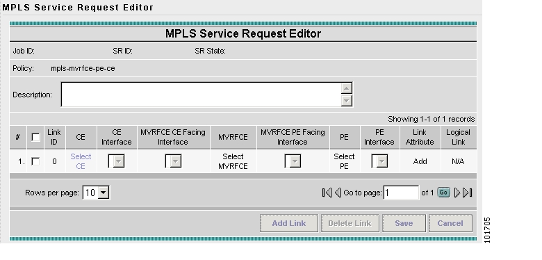
Step 5
The MPLS Service Request Editor window appears, as shown in Figure 8-8.
Figure 8-8 MPLS Service Request Editor - Select CE
Step 6
The CPE for MPLS VPN Link window appears.
Step 7
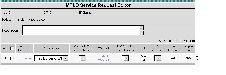
The MPLS Service Request Editor window appears, as shown in Figure 8-9.
Figure 8-9 MPLS Service Request Editor - Select MVRFCE
Step 8
Step 9
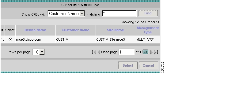
The MVRFCE for MPLS VPN Link window appears, as shown in Figure 8-10.
Figure 8-10 PE for MPLS VPN Link
Step 10
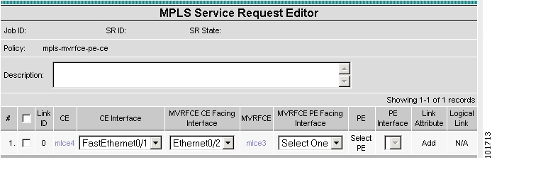
The MPLS Service Request Editor window appears, as shown in Figure 8-11.
Figure 8-11 MPLS Service Request Editor - Select MVRFCE CE Facing Interface
Step 11
Step 12
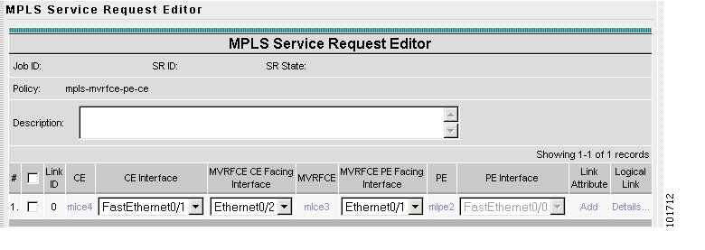
The MPLS Service Request Editor window appears, as shown in Figure 8-12.
Figure 8-12 PE for MPLS VPN Link
Step 13
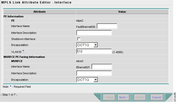
The MPLS Link Attribute Editor - Interface window appears, as shown in Figure 8-13.
Figure 8-13 MPLS Link Attribute Editor - Interface
PE Information
Step 14
Step 15
MVRFCE PE Facing Information
Step 16
Step 17
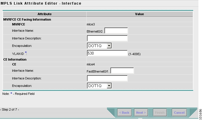
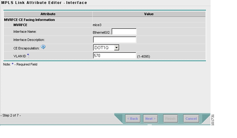
The MPLS Link Attribute Editor - Interface window appears, as shown in Figure 8-14.
Figure 8-14 MPLS Link Attribute Editor - Interface
MVRFCE CE Information
Step 18
Step 19
MVRFCE PE-Facing Information
Step 20
Step 21
The MPLS Link Attribute Editor - IP Address Scheme window appears for PE-MVRF-CE interface address/mask.
Step 22
The MPLS Link Attribute Editor - IP Address Scheme window appears for MVRFCE-CE interface address/mask.
Step 23
The MPLS Link Attribute Editor - Routing Information window reappears for PE-MVRF-CE routing information.
Step 24
The MPLS Link Attribute Editor - Routing Information window reappears for MVRFCE-CE routing information.
Step 25
The MPLS Link Attribute Editor - VRF and VPN window appears.
Step 26
The Select CERCs window appears.
Step 27
Step 28
Step 29
Step 30
Step 31
The MPLS Link Attribute Editor - VRF and VPN window reappears. The MPLS Link Attribute Editor - VRF and VPN window reappears showing the VPN.
Step 32
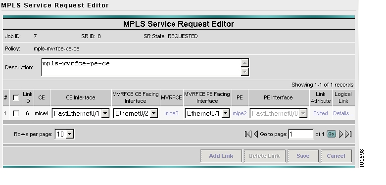
The MPLS Service Request Editor window reappears, as shown in Figure 8-15.
Figure 8-15 MPLS Service Request Editor
Step 33
The MPLS Service Requests window reappears showing that the MPLS VPN MVRFCE PE-CE Service Request is in the Requested state and ready to deploy.
Creating MVRFCE PE-NoCE Service Requests
To create an MVRFCE PE-NoCE service request, perform the following steps:
Step 1
The Service Requests window appears.
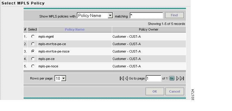
Step 2
The Select MPLS Policy window appears, as shown in Figure 8-16.
Figure 8-16 Choose MPLS Policy
Step 3
Step 4
The MPLS Service Request Editor window appears.
Step 5
The MPLS Service Request Editor window appears, as shown in Figure 8-17.
Figure 8-17 MPLS Service Request Editor - Select MVRFCE
Step 6
The CPE for MPLS VPN Link window appears.
Step 7
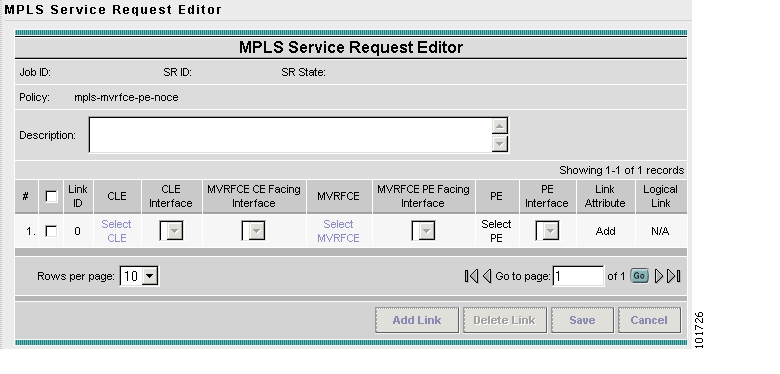
The MPLS Service Request Editor window appears, as shown in Figure 8-18.
Step 8
Figure 8-18 MPLS Service Request Editor - MVRFCE CE Facing Interface
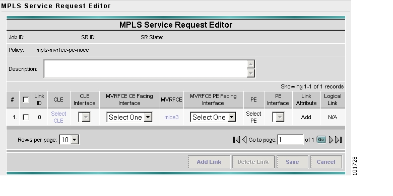
Step 9
Step 10
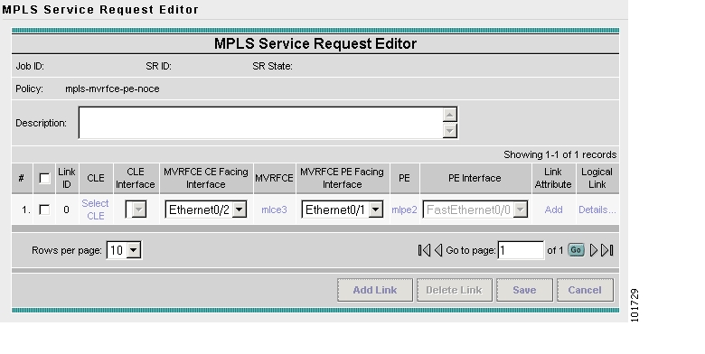
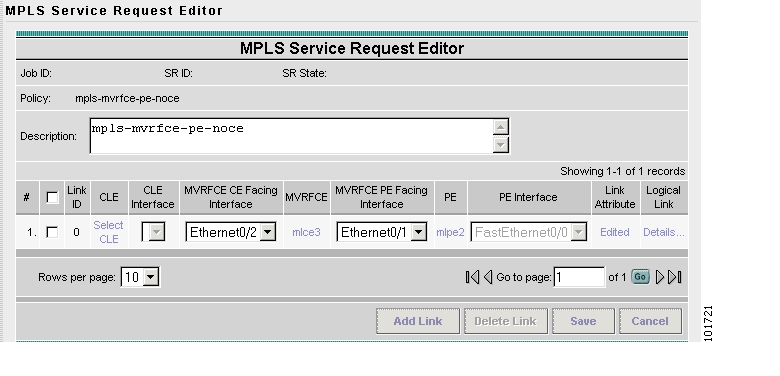
The MPLS Service Request Editor window appears, as shown in Figure 8-19.
Figure 8-19 MPLS Service Request Editor
Step 11
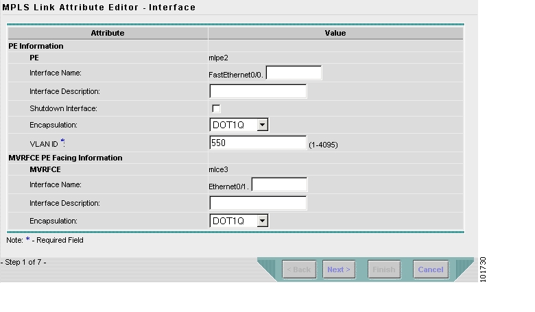
The MPLS Link Attribute Editor - Interface window appears, as shown in Figure 8-20.
Figure 8-20 MPLS Link Attribute Editor - Interface
PE Information
Step 12
Step 13
MVRFCE PE Facing Information
Step 14
Step 15
The MPLS Link Attribute Editor - Interface window appears, as shown in Figure 8-21.
Figure 8-21 MPLS Link Attribute Editor - Interface
MVRFCE CE Information
Step 16
Step 17
MVRFCE PE Facing Information
Step 18
Step 19
The MPLS Link Attribute Editor - IP Address Scheme window appears for PE-MVRF-CE interface address/mask.
Step 20
The MPLS Link Attribute Editor - IP Address Scheme window appears for MVRFCE-CE interface address/mask.
Step 21
The MPLS Link Attribute Editor - Routing Information window reappears for PE-MVRF-CE routing information.
Step 22
The MPLS Link Attribute Editor - Routing Information window reappears for MVRFCE-CE routing information.
Step 23
The MPLS Link Attribute Editor - VRF and VPN window appears.
Step 24
Step 25
The MPLS Service Request Editor window reappears, as shown in Figure 8-22.
Figure 8-22 MPLS Service Request Editor
Step 26
The MPLS Service Requests window reappears showing that the MPLS VPN MVRFCE PE-NoCE Service Request is in the Requested state and ready to deploy.
Creating an Unmanaged MVRFCE
The unmanaged MVRFCE feature is similar to the unmanaged CE feature in so far as the service provider does not use ISC to upload or download configurations to the CPE. This feature is similar to the managed MVRFCE feature in so far as ISC creates a link with three devices: a PE, an MVRFCE, and a CE.
In the unmanaged scenarios, the customer configures the CPE manually. To automate the process of configuring the unmanaged MVRFCE, the service provider can use ISC to generate the configuration and then send it to the customer for manual implementation.
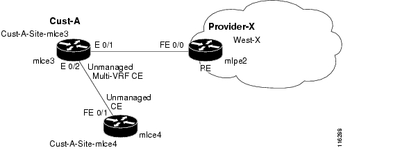
Figure 8-23 shows an overview of a network topology with MPLS VPN MVRFCE PE-CE links.
Figure 8-23 Unmanaged MVRFCE PE-CE Network Topology
The network topology in Figure 8-23 shows a service provider (Provider-X) and a customer (Cust-A). The Provider contains one Region (West-X) and one PE (mlpe2). The Customer contains an MVRFCE (mlce3) and a CE (mlce4). Both of these CPEs are unmanaged.
![]()
![]()
![]()
![]()
![]()
![]()
![]()
![]()
Posted: Mon Feb 18 15:18:48 PST 2008
All contents are Copyright © 1992--2008 Cisco Systems, Inc. All rights reserved.
Important Notices and Privacy Statement.