|
|

This chapter describes how to turn on and turn off the system and what the controls and indicators mean.
Turning on the system refers to the act of plugging the power cord of your system into the power source and starting the operating system.
Complete the following steps to turn on the system:
 |
Note Plugging the power cord into a power source might cause the system to start automatically. This is an acceptable action. |
Step 2 Wait 30 seconds; then, press the power-control button on the front of the system.
Step 3 If you have a SCSI hard disk drive in your system, check the hard disk drive status light and activity light to verify that the hard disk drives are operating properly. (See "System Controls and Indicators" section for the location of the status indicators.)
 |
Note The green light flashes rapidly (three flashes per second) when the controller is identifying the drive. |
Turning off the system refers to the act of disconnecting the system from the power source.
Complete the following steps to turn off the system:
 |
Note Each operating system is different. Some allow an immediate shutdown. Others require an orderly shutdown procedure. |
Step 2 Press the power-control button on the front of the system. This will put the system in standby mode.
Step 3 Disconnect the system from the power source.
Standby puts the system into a wait state. When in a wait state, the system is not running the operating system, and all core logic is shut down except for the service processor.
Complete the following steps to put the system into the standby mode:
 |
Note Each operating system is different. Read all the documentation about shutting down the operating system before continuing. |
Step 2 Press the power-control button on the front of the system.
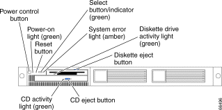
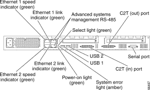
This section identifies the controls and indicators on the front (see Figure 3-1) and the back (see Figure 3-2) of your system.
\
Power-control button: Press this button to manually turn the system on or off.
Power-on light: This green LED lights and stays on when you turn on your system and blinks when the system is in standby mode.
Reset button: Press this button to reset the system and run the power-on self-test (POST). You might need to use a pen or the end of a straightened paperclip to press the button.
Select button/indicator: Press this button to select the system in the C2T chain. The green LED on this button lights when the monitor, keyboard, and mouse are logically connected to this system.
System-error light: This amber LED lights when a system error occurs. An LED on the Light Path Diagnostics panel on the system board will also be on to further isolate the error.
Diskette drive activity light: When this LED is on, it indicates that the diskette drive is in use.
Diskette-eject button: Push this button to release a diskette from the drive.
CD eject button: Push this button to release a CD from the drive.
CD drive activity light: When this light is on, it indicates that the CD-ROM drive is in use.

Ethernet 1 speed indicator: This green LED lights when the speed of the Ethernet LAN that is connected to Ethernet port 1 is 100 Mbps.
Ethernet 1 link indicator: This green LED lights when there is an active link connection on the 10BASE-T or 100BASE-TX interface for Ethernet port 1.
Advanced System Management: The RS-485 ports are used for creating a system management bus between several systems.
Select light: This green LED lights when the monitor, keyboard, and mouse are logically connected to this system. This light duplicates the Select button LED on the front of the system.
C2T (Out) port: This port is used to connect the system to a keyboard, monitor, and pointing device. It is also used to connect multiple systems together to share a single keyboard, monitor, and pointing device.
Serial port: Signal cables for modems or other serial devices connect here to the 9-pin serial port connector.
C2T (In) port: This port is used to connect multiple systems together to share a single keyboard, monitor, and pointing device.
USB 2 connector: This connector is used to attach Universal Serial Bus (USB) to Universal Serial Bus 2.
USB 1 connector: This connector is used to attach Universal Serial Bus (USB) to Universal Serial Bus 1.
System-error light: This amber LED lights when a system error occurs. An LED on the Light Path Diagnostics panel on the system board will also be on to further isolate the error. This light duplicates the system error light on the front of the system.
Power-on light: This green LED lights and stays on when you turn on your system and will blink when the system is in standby mode. This light duplicates the power on light on the front of the system.
Ethernet 2 link indicator: This green LED lights when there is an active link connection on the 10BASE-T or 100BASE-TX interface for Ethernet port 2.
Ethernet 2 speed indicator: This green LED lights when the speed of the Ethernet LAN connected to Ethernet port 2 is 100 Mbps.
After you have the IE2100 Series installed and power has been applied, you need to load the Configuration Registrar software application. For information about how to load the software, refer to the Cisco Intelligence Engine 2100 Series Configuration Registrar Administrator's Guide, which can be found online at www.cisco.com. Look for this information under IE2100 Series Products, which is listed under Network Management.
For the latest information about the Configuration Registrar, check the Release Notes for Cisco Intelligence Engine 2100 Series Configuration Registrar, which can be also found online at www.cisco.com.
![]()
![]()
![]()
![]()
![]()
![]()
![]()
![]()
Posted: Wed Jun 19 10:21:21 PDT 2002
All contents are Copyright © 1992--2002 Cisco Systems, Inc. All rights reserved.
Important Notices and Privacy Statement.