cc/td/doc/product/rtrmgmt/cupm/cupm10
hometocprevnextglossaryfeedbacksearchhelp
PDF

Table Of Contents

Administering Infrastructure

Overview

Configuring Processors

Creating Call Processors

Changing Call Processor Information

Synchronizing Call Processors

Creating Unified Message Processors

Changing Unified Message Processor Information

Synchronizing Unified Message Processors

Working with Provisioning Manager Domains

Using the Customer Domain Template

Creating a Domain

Configuring a Domain

Synchronizing Domains

Editing a Domain's Provisioning Attributes

Viewing a Domain's Synchronization Log

Working with Service Areas

Creating Service Areas

Configuring Service Areas

Editing a Service Area's Provisioning Attributes

Creating Directory Number Blocks

Specifying Default Call Forward Settings

Using Templates—Infrastructure Configuration

Working with Configuration Templates

Creating Configuration Templates

Updating an Existing Template

Renaming Configuration Templates

Creating Copies of Configuration Templates

Deleting Configuration Templates

Generating a Configuration Using a Template

Using Batch Provisioning

Creating Batch Action Files

Creating Batch Projects

Working with Batch Projects


Administering Infrastructure


Overview

Through its partitioning capabilities, Provisioning Manager provides a secure environment wherein enterprises can deliver services to multiple geographical or organizational segments of their company.

Enterprises can delegate operational control to administrators and/or subscribers. In some cases, a company may be regionally distributed and require a secure environment for each region.

In Provisioning Manager, you can partition a shared environment using Domains. Domains contain information on Call Processors, Unified Message Processors, and Service Areas. Service areas then contain information such as route partitions, calling search spaces, device groups, and directory numbers. The combination of these components determines the dial plans that are available to individual subscribers.

When a customer and related phones, lines, and directory numbers are configured in a specific Domain, Provisioning Manager ensures that the associated Route Partition and calling search spaces are used.

You can configure Provisioning Manager so that only customers and subscribers within a given Domain and Service Area have access to a specific subset of operational capabilities. You can further control access by limiting access to services that are available within a Domain, and by limiting access to the users and resources (for example, Cisco Unified CallManagers) that are used to deliver the services. An individual company can have multiple Domains depending on its business requirements.

For more information, see the following sections:

Configuring Processors

Working with Provisioning Manager Domains

Working with Service Areas

Using Templates—Infrastructure Configuration

Using Batch Provisioning

Configuring Processors

This section provides information on how to create and synchronize Call Processors and Unified Message Processors.

This section contains the following sections:

Creating Call Processors

Changing Call Processor Information

Synchronizing Call Processors

Creating Unified Message Processors

Changing Unified Message Processor Information

Synchronizing Unified Message Processors

In Provisioning Manager, you create Call Processors and Unified Message Processors. Call Processors are proxies for each instance of a Cisco Unified CallManager or Cisco Unified CallManager Express. Unified Message Processors are proxies for each instance of a Cisco Unity, Cisco Unity Express, or Cisco Unity Connection.

Synchronizing the data in the Cisco Unified CallManager and Cisco Unity systems with the Call Processors and Unified Message Processors, and then synchronizing with the Domains populates Provisioning Manager with the existing active users and services, and provides a consolidated view of all of the infrastructure and subscriber information. After a Domain synchronization, you can use Provisioning Manager to directly manage the individual user account. You no longer have to use the underlying Cisco Unified CallManager or Cisco Unity systems.


Note Once a Call Processor or Unified Message Processor is created and synchronized, do not change the type of device or version of the device for the processor. For example, if you create a Call Processor for a Cisco Unified CallManager version 4.1, do not change the Call Processor type to a Cisco Unified CallManager Express, or the version of the Cisco Unified CallManager to version 4.2.


Creating Call Processors

A Call Processor is a proxy within Provisioning Manager for a single instance of a Cisco Unified CallManager or Cisco Unified CallManager Express.

Table 5-1 describes the fields for creating a Call Processor.

Table 5-1 Call Processor Fields 

Field
Description

Name

Call Processor name.

Type

Cisco Unified CallManager or Cisco Unified CallManager Express.

IP Address

IP address of the Cisco Unified CallManager or Cisco Unified CallManager Express.

Version

Cisco Unified CallManager or Cisco Unified CallManager Express version number.

Device Protocol

Protocol used to communicate with the device.

User Name

Username based on the protocol selected.

Password (and confirm)

Password for the Cisco Unified CallManager or Cisco Unified CallManager Express user name.

Enable Password (and confirm)

The enable password configured on Cisco Unified CallManager Express.

Extension Mobility Details (Optional)

Service Name

The name of the Extension Mobility Service configured on a Call Processor.

Service URL

The URL of the extension mobility service configured on the Call Processor:

http://<IPAddress>/emapp/EMAppServlet?device=#DEVICENAME#

Where <IPAddress> is the name or the IP address of the server where Extension Mobility is installed.


Note After you have created a Call Processor, you cannot delete it.


Step 1 Select Infrastructure Configuration > Set Up Devices > Call Processors. The Call Processor Configuration page appears.

Step 2 Click New Call Processor.

Step 3 Enter the following information for the Call Processor:

Name

Type

IP address

Version

Device protocol

LDAP directory integration—only available for Cisco Unified CallManager 5.0


Note This value must exactly match the value configured on the Cisco Unified CallManager. If a Cisco Unified CallManager is integrated with an external LDAP, subscribers are not created through Provisioning Manager; instead they are synchronized through the Cisco Unified CallManager. When placing an order, if a subscriber is not available on the Cisco Unified CallManager, the workflow subsystem waits for a pre-defined period of time (24 hours by default) for the subscriber to be available on the Cisco Unified CallManager and then continues processing the order. The 24 hour period can be configured on Provisioning Manager in the ipt.properties file. Change the following two settings:

dfc.oem.extdir.retries: 24

dfc.oem.extdir.retry_interval: 3600


Username

Password (and confirm)

Enable password (and confirm)—only available for Cisco Unified CallManager Express

Extension mobility (if available)—only available for Cisco Unified CallManager

Service name

Service URL

Step 4 Click Save.


Changing Call Processor Information

After a Call Processor is created, you can update its information.


Note Once a Call Processor is created and synchronized, do not change the type of device or version of the device for the Call Processor. For example, if you create a Call Processor for a Cisco Unified CallManager version 4.1, do not change the Call Processor type to a Cisco Unified CallManager Express, or the version of the Cisco Unified CallManager to version 4.2.


Step 1 Select Infrastructure Configuration > Set Up Devices > Call Processors. The Call Processor Configuration page appears.

Step 2 Click View Call Processor. The Choose a Call Processor dialog box appears.

Step 3 Select the Call Processor that you require. The View Call Processor page appears.

Step 4 In the Options pane, click Update. The Update Call Processor page appears.

Step 5 Edit the fields as required. (For explanations of the fields, see Creating Call Processors.)

Step 6 Click Save.


Synchronizing Call Processors

To synchronize a Call Processor, you synchronize the infrastructure and subscribers. The infrastructure data are the configurations that are required to exist on Call Processor before Provisioning Manager can configure subscriber services.

You use the infrastructure synchronization to synchronize the infrastructure data with the Call Processor infrastructure data. The infrastructure synchronization retrieves Call Processor information that is used across multiple subscribers.

Examples of the type of infrastructure data stored are described in the following:

VoiceDeviceGroup—A device pool in Cisco Unified CallManager.

CallSearchSpaces—A Calling Search Space (CSS) in Cisco Unified CallManager.

RoutePartitions—A partition in Cisco Unified CallManager.

You use the subscriber synchronization to synchronize the subscriber data in Provisioning Manager with the Call Processor subscriber data.

Examples of the type of subscriber data stored are described in the following:

Directory Number—Directory numbers in Cisco Unified CallManager.

VoiceTerminal—A phone that is not a CTI port in Cisco Unified CallManager.

VoIPInfo—Users must be subscribers in Provisioning Manager. However, this information is not synchronized from a Call Processor.

You can execute the synchronizations independently and in any order. However, to preserve the integrity of the data, it is recommended that you run the synchronizations together, and in the following order:

1. Infrastructure synchronization.

2. Subscriber synchronization.


Note After a new Provisioning Manager installation, the infrastructure synchronization must be executed first.


Note You should not run more than one synchronization at a time (Processor or Domain synchronization). Run all synchronizations sequentially.


Step 1 Select Infrastructure Configuration > Set Up Devices > Call Processors. The Call Processor Configuration page appears.

Step 2 Click View Call Processor. The Choose a Call Processor dialog box appears.

Step 3 Select the Call Processor that you require. The View Call Processor page appears.


Note If the Call Processor was synchronized previously, the details are displayed in the Synchronization section.


Step 4 In the Options pane, click Synchronize.

Step 5 You can run an infrastructure or subscriber synchronization. Click Start under the synchronization that you desire.

After the synchronization has completed, the Synchronization section displays the synchronization information.

Step 6 Click Done.


Creating Unified Message Processors

A Unified Message Processor is a proxy within Provisioning Manager for each instance of Cisco Unity, Cisco Unity Express, and Cisco Unity Connection. Table 5-2 describes the fields for creating a Unified Message Processor.


Note The fields that are displayed in the Configure a New Unified Message Processor page depend on the Cisco Unity type you select in the Type field. Not all fields will appear.


Table 5-2 Configuring a Unified Message Processor Fields 

Field
Description

Name

Name provided by the user.

Type

Type of Cisco Unity (Cisco Unity, Cisco Unity Connection, or Cisco Unity Express).

IP Address

Cisco Unity, Cisco Unity Connection, or Cisco Unity Express system IP address.

Version

The version of device.

User Name

Cisco Unity or Cisco Unity Connection database username.

Password (and confirm)

Cisco Unity or Cisco Unity Connection database password.

Host Router IP Address

IP address of the router where Cisco Unity Express is installed.

Protocol

Protocol used to connect to the device.

(Optional) Host Router User Name

Username of the router where Cisco Unity Express is installed.

(Optional) Host Router Password (and confirm)

Password for the router where Cisco Unity Express is installed.

Host Router Enable Mode Password (and confirm)

Enable mode password for the router where Cisco Unity Express is installed.

(Optional) CUE Line User Name

Username for the Cisco Unity Express module.

(Optional) CUE Line Password (and confirm)

Password for the Cisco Unity Express module.

Service Engine Interface Number

The interface number of the Cisco Unity Express service engine on the router.


Step 1 Select Infrastructure Configuration > Set Up Devices > Unified Message Processors. The Unified Message Processor Configuration page appears.

Step 2 Click New Unified Message Processor. The Configure a New Unified Message Processor page appears.

Step 3 Enter a name for the Unified Message Processor.

Step 4 Select the type of Unified Message Processor.

Step 5 The information that you must enter varies, depending on which type of device you are adding (for explanations of the fields, see Table 5-2):

If you are adding a Cisco Unity or Cisco Unity Connection, enter the following:

IP address

Version

Username

Password (and confirm)

Port number

If you are adding a Cisco Unity Express, enter the following:

Host router IP address

Version

Protocol

Host router username

Host router password (and confirm)

Host router enable mode password (and confirm)

Cisco Unity Express line username

Cisco Unity line password (and confirm)

Service engine interface number

Step 6 Click Save.


Changing Unified Message Processor Information

You can update the Unified Message Processor information.


Note Once a Unified Message Processor is created and synchronized, do not change the type of device or version of the device for the Unified Message Processor. For example, if you create a Unified Message Processor for a Cisco Unity version 4.1, do not change the Unified Message Processor type to a Cisco Unity Connection, or the version of the Cisco Unity to version 4.2.


Step 1 Select Infrastructure Configuration > Set Up Devices > Unified Message Processors. The Unified Message Processor Configuration page appears.

Step 2 Click View Unified Message Processors. The Choose a Unified Message Processor dialog box appears.

Step 3 Select the Unified Message Processor that you require. The View Unified Message Processor page appears.

Step 4 In the Options pane, click Update. The Update Unified Message Processor page appears.

Step 5 Edit the fields as required. (For explanations of the fields, see Table 5-2.)

Step 6 Click Save.


Synchronizing Unified Message Processors

To synchronize a Unified Message Processor, you synchronize the infrastructure and subscribers. The infrastructure data are the configurations that are required to exist on Unified Message Processors before Provisioning Manager can configure subscriber services.

You use the infrastructure synchronization to synchronize the unified messaging infrastructure data in Provisioning Manager with the Unified Message Processor.

The infrastructure data consists of the following:

SubscriberTemplate—A Subscriber Template in Cisco Unity, Cisco Unity Connection, and the email message processor.

UnifiedMessagingFeatureSpecification—A class of service in Cisco Unity, Cisco Unity Connection, and the email message processor.

You use the subscriber synchronization to synchronize the unified messaging subscriber data in Provisioning Manager with the Unified Message Processor.

The subscriber data consists of the following:

UMInfo—A subscriber in Cisco Unity, Cisco Unity Connection, and Cisco Unity Express in conjunction with their voicemail and email information.

VoiceMailInfo—A subscriber in Cisco Unity, Cisco Unity Connection, and Cisco Unity Express in conjunction with UMInfo and EmailInfo.

EmailInfo—A subscriber in Cisco Unity and Cisco Unity Connection in conjunction with VoiceMailInfo and UMInfo.

You can execute the synchronizations independently and in any order. However, to preserve the integrity of the data, it is recommended that you run the synchronizations together, and in the following order:

1. Infrastructure synchronization.

2. Subscriber synchronization.


Note After a new Provisioning Manager installation, the infrastructure synchronization must be executed first.


Note You should not run more than one synchronization at a time (Processor or Domain synchronization). Run all synchronizations sequentially.


Step 1 Select Infrastructure Configuration > Set Up Devices > Unified Message Processors. The Unified Message Processor Configuration page appears.

Step 2 Click View Unified Message Processor. The Choose a Unified Message Processor dialog box appears.

Step 3 Select the Unified Message Processor that you require. The View Unified Message Processor page appears.


Note If the Unified Message Processor was synchronized previously, the details will be displayed in the Synchronization sections.


Step 4 In the Options pane, click Synchronize.

Step 5 You can run an infrastructure or subscriber synchronization. Click Start under the synchronization that you desire.

After the synchronization has completed, the Synchronization section displays the synchronization information.


Note If during the synchronization of a Cisco Unity Express you encounter device connection errors, close all telnet sessions on the Cisco Unity Express system and restart the synchronization. Cisco Unity Express only allows one telnet session at a time. Provisioning Manager will not be able to synchronize with a Cisco Unity Express device that has another telnet session open.


Step 6 Click Done.


Working with Provisioning Manager Domains

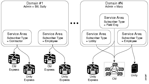
Provisioning Manager introduces the concept of Domains and Service Areas. Domains are groupings of subscribers. For each grouping, one or more system users can be authorized to manage services for subscribers within that Domain. In addition, rules or policies may be set on a Domain; those rules and policies will apply to services for subscribers in that Domain. Common policies can also be applied on operations within a Domain.

To use Domains in Provisioning Manager, you must do the following:

Create and configure the Domain—Includes assigning a Call Processor and Unified Message Processor (optional).

Create and configure Service Areas—Includes selecting call search spaces, route partitions and, voice device group; specifying user types that have access to the Service Area; and configuring Directory Number Blocks.

Figure 5-1 Domain Configuration

Using the Customer Domain Template

If your implementation will have more than one Domain, you can configure the Customer Domain Template according to the default business rules and user types that you require for your implementation.

When you create new Domains, they inherit the standard set of business rules and user types from the Customer Domain Template. You can then change the business rules and user types as required for each new Domain. Changes made to the Customer Domain Template affect only new Domains created after that point.

The Customer Domain Template is created by default when you install Provisioning Manager. You configure it by specifying business rules and subscriber roles for it the same way that business rules and subscriber roles are specified for new Domains.

Creating a Domain

Table 5-3 describes the fields required for creating a Domain.

Table 5-3 Fields for Creating Domains

Field
Description

Domain ID

ID of the Domain. Valid values are alphanumeric characters (A-Z, a-z, 0-9), underscore (_), hyphen (-), asterisk (*), and period (.).

(Optional) Description

Description of the Domain.


Step 1 Select Infrastructure Configuration > Set Up Deployment > Domains. The Domain Configuration page appears.

Step 2 In the Options pane, click New Domain. The Configure a New Domain page appears.

Step 3 Complete the fields as required.

Step 4 Click Save. The Update Domain page appears. For configuring a Domain, see Configuring a Domain.


Configuring a Domain

After you have created a Domain, you must select one or more Call Processors for it. You can also select one or more Unified Message Processors. The Domain information includes Service Areas, and subscriber roles that have access to your new Domain.


Note You must create the Call Processor and Unified Message Processor before you can add them to a Domain. Call Processors and Unified Message Processors can be shared across Domains.


Table 5-4 describes the fields required for configuring a Domain.

Table 5-4 Domain Configuration Fields

Field
Description

Domain ID

ID of the Domain. Valid characters are: A-Z, a-z,
0-9, . _ - *.

Description

Description of the Domain.

Call Processor

Call Processors for the Domain.

Unified Message Processor

Unified Message Processors for the Domain.

Subscriber Roles

Includes the default Provisioning Manager subscriber roles.

Service Area

Geographic, organizational, or technology boundaries for the Domain.


Step 1 Select Infrastructure Configuration > Set Up Deployment > Domains. The Domain Configuration page appears.

Step 2 Click View Domain. The Choose a Domain dialog box appears.

Step 3 Select the Domain that you require. The View Domain page appears.

Step 4 In the Options pane, click Update. The Update Domain page appears.

Step 5 Do the following:

(Optional) Enter a description.

Select a Call Processor.

(Optional) Select a Unified Message Processor.

(Optional) Create a new Service Area for the Domain or edit the selected Service Area.

Step 6 Click Save.


Synchronizing Domains

During a Domain synchronization, Provisioning Manager does the following:

Associates the voicemail, email, and unified messaging data in the Unified Message Processor with the user information in Provisioning Manager.

Synchronizes the assigned voice mail directory numbers in the Unified Message Processor to those in the Call Processor.

Synchronizes subscribers and their ordered products with the Provisioning Manager inventory, creates new subscribers, and updates their subscriber records.

Synchronizes user accounts and updates Provisioning Manager so that users can log in (logins are created only if the self-care rule is enabled; see CreateSelfCareAccounts, page 6-4).

To fully synchronize a Domain, you must perform the following:

1. For each Call Processor in the Domain, perform an infrastructure and subscriber synchronization.

2. For each Unified Message Processor in the Domain, perform an infrastructure and subscriber synchronization.

3. Perform a Domain synchronization.


Note If a Call Processor or a Unified Message Processor in the Domain is synchronized, it is recommended that a Domain synchronization also be done.


Note When running Domain synchronization, remember the following:

If you use a subscriber synchronization on a Cisco Unified CallManager Express to add subscribers to Provisioning Manager, the first name, last name, phone number, and department data is not obtained by Provisioning Manager. The Manage Subscriber page displays Unknown in these fields."

You can update the subscriber information through Provisioning Manager, but be aware that this information will be pushed to the Cisco Unified CallManager Express system, and will overwrite any existing information for the user in the ephone description field.

You should not run more than one synchronization at a time (Domain or Processor synchronization). Run all synchronizations sequentially.

If a Cisco Unified CallManager Express is the only device present in a Domain and Service Area , during Domain synchronization subscribers are not created in Provisioning Manager if the ephone username command is not configured in Cisco Unified CallManager Express. Make sure the ephone username command is configured in Cisco Unified CallManager Express for all subscribers.


Step 1 Select Infrastructure Configuration > Set Up Deployment > Domains. The Domain Configuration page appears.

Step 2 Click View Domain. The Choose a Domain dialog box appears.

Step 3 Select the Domain that you require. The View Domain page appears.


Note If the Domain was synchronized previously, the details are displayed in the Last Synchronization section.


Step 4 In the Options pane, click Synchronize.

Step 5 Click Start.

After the synchronization has completed, the Last Synchronization section displays the synchronization information.

Step 6 Click Done.


Note After the Domain synchronization completes, a log is created, listing the objects that could not be assigned; see Viewing a Domain's Synchronization Log.


Configuring Business Rules for Domain Synchronization

For the Domain synchronization to work properly, you must configure at least one of the following rules:

AssociateAllUsersInCallProcessor—If enabled, all user accounts in all of the Call Processors in the Domain are assigned to the Domain being synchronized. This rule overrides the AssociateUsersByDeptCode rule.

AssociateUsersByDeptCode—If enabled, the Domain synchronized associates only the Call Processor user accounts whose department code matches one in the list specified in the rule configuration.

AssociateAllUsersInUMProcessor—If enabled, all user accounts in a given Unified Message Processor are associated to a Domain, including those accounts without a corresponding Call Processor user account. If disabled, only user accounts in the given Unified Message Processor that have a matching Call Processor user account are associated.


Note By default, none of these rules are configured. If none of the rules are enabled and a Domain synchronization is run, Provisioning Manager only associates the Call Processor accounts where the department code is the same as the name of the Domain.


Editing a Domain's Provisioning Attributes

You can set provisioning attribute at the Domain level. All provisioning attributes set at other levels (Service Area, subscriber type, Advanced Order) take precedence over provisioning attributes set at the Domain level. For more information on provisioning attributes, see Configuring Provisioning Attributes, page 6-13.


Step 1 Select Infrastructure Configuration > Set Up Deployment > Domains. The Domain Configuration page appears.

Step 2 Click View Domain. The Choose a Domain dialog box appears.

Step 3 Select the Domain that you require. The View Domain page appears.

Step 4 In the Options pane, click Edit Provisioning Attributes. The Provisioning Attribute Management page appears.

Step 5 Update attributes as desired, then click Done. (For descriptions of the provisioning attributes, see Configuring Provisioning Attributes, page 6-13.)


Viewing a Domain's Synchronization Log

When a Domain synchronization occurs, a log is created. The log lists the products that could not be assigned to a Service Area during a Domain synchronization. This log is replaced each time a Domain synchronization occurs.


Step 1 Select Infrastructure Configuration > Set Up Deployment > Domains. The Domain Configuration page appears.

Step 2 Click View Domain. The Choose a Domain dialog box appears.

Step 3 Select the Domain that you require. The View Domain page appears.

Step 4 In the Options pane, click Synchronize.

Step 5 Click View Detailed Synchronization Log at the bottom of the page. The log appears.


Working with Service Areas

You use Service Areas to structure and manage the required IP telephony and messaging services across geographic, organizational, or technology boundaries. The Service Area determines the mappings from the business view of the service to the technology delivering those services. For example, on a Service Area associated to a Cisco Unified CallManager, a Service Area defines the device group, route partition, calling search spaces, location, external phone number mask that the products will use within Cisco Unified CallManager.

In this case, when you configure a Service Area, you have a list of route partitions that can be assigned to it based on the selected Call Processor for the Service Area. If the Service Area does not have any associated route partition, then the directory numbers and lines are created in the default route partition in Cisco Unified CallManager.

For Cisco Unity and Cisco Unity Connection Unified Message Processors, if you assign a Unified Message Processor to a Service Area, the Subscriber Template (with or without the TTS feature) and Subscriber CoS (with or without the TTS feature) can be configured. These templates can be used for voicemail provisioning of subscribers in the Service Area.


Note For Service Areas with Call Processors based on Cisco Unified CallManager Express, only device groups are available for selection. Calling search spaces and route partitions are not available.


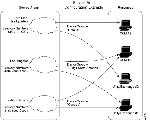
Figure 5-2 shows how the associations with Service Area to route partition, device group, calling search spaces, and Domain are established when you create and configure the Service Area. Service areas also determine the key voicemail settings and call forwarding behaviors.

Figure 5-2 Service Area Configuration

Creating Service Areas

Table 5-5 describes the fields for creating a Service Area.

Table 5-5 Fields for Creating a Service Areas

Field
Description

Service Area ID

Name of the Service Area. Valid values are alphanumeric characters (A-Z, a-z, 0-9), underscore (_), hyphen (-), asterisk (*), and period (.).

Domain

The Domain that the Service Area belongs to.


Step 1 Select Infrastructure Configuration > Set Up Deployment > Service Areas. The Service Area Configuration page appears.

Step 2 Click New Service Area.

Step 3 In the Service Area ID field, type the name of the new Service Area.

Step 4 Select the Domain that you want the Service Area to belong to.

Step 5 Click Save. The Edit Service Area page appears. For configuring a Service Area, see Configuring Service Areas.


Configuring Service Areas

When configuring a Service Area, you can do the following:

Map the Service Area to the corresponding Call Processor objects by specifying its Call Processors and related objects (for a Cisco Unified CallManager, some examples are call search space, route partition, voice device group) and Unified Message Processor.

Specify the subscriber types for the Service Area (only users within a Service Area can order products from it).


Note The Employee subscriber role is the default based on the Domain rule DefaultUserType.


Create directory number blocks for the Service Area users.

Set a default phone number mask and/or call forward settings for new lines ordered within the Service Area.


Note Once a Service Area is assigned to a Domain, it cannot be changed. Further, once a Call Processor or Unified Message Processor is assigned to a Service Area, it cannot be changed.


Table 5-6 describes the fields for configuring a Service Area.

Table 5-6 Service Area Configuration Fields 

Field
Description

Service Area ID

Name of the Service Area.

Domain

Domain that the Service Area belongs to.

Call Processor Settings

You will have different settings available to you, depending on the type of device that your Call Processor is.


Name

Call processor for the Service Area (read-only).


Phone Protocol

The protocol to be configured when phones are ordered. You will have an option of either SIP or SCCP for Cisco Unified CallManager versions which support SIP. Otherwise SCCP is displayed.

Note This field only appears if you selected a Cisco Unified CallManager 5.0.


Call Search Space (phone)

Call search space to be assigned to phones and extension mobility profiles. It can be left blank. It only applies to Cisco Unified CallManager.


Call Search Space (line)

Call search space to be assigned to lines on a phone or extension mobility profile. It can be left blank. It only applies to Cisco Unified CallManager.


Location

Location to be assigned to a device. It only applies to Cisco Unified CallManager.


Route Partition

Route partition for the Service Area. It only applies to Cisco Unified CallManager. This is the same as a partition in Cisco Unified CallManager.


Voice Device Group

Voice device group for the Service Area.


External Phone Number Mask

Indicate phone number (or mask) that is used to send caller ID information when a call is placed from the Service Area.

You can enter a maximum of 30 characters. The Xs represent the directory number and must appear at the end of the pattern. For example, if you specify a mask of 972813XXXX, an external call from extension 1234 displays a caller ID number of 9728131234.


Default Call Forward Settings

Default settings for new phone lines ordered in the Service Area (see Specifying Default Call Forward Settings). It only applies to Cisco Unified CallManager.

For example, you can specify a common rollover number or voicemail number. The following default forwarding options are available:

Forward All

Forward Busy

Forward No Answer

Unified Message Processors

You will have different settings available to you, depending on the type of device that your Unified Message Processor is.


Name

Unified Message Processor for the Service Area (if applicable).


Email Processors

Available only for Cisco Unity Connection and it is integrated with an external Exchange Server for IMAP Client support.


Subscriber Template with TTS Enabled

Subscriber Template to be used to enable unified messaging for a subscriber in the Unified Message Processor.


Subscriber Template without TTS Enabled

Subscriber Template to be used to disable unified messaging for a subscriber in the Unified Message Processor.


Subscriber CoS with TTS Enabled

Class of Service Template to be used to enable unified messaging for a subscriber in the Unified Message Processor. It applies to Cisco Unity and Cisco Unity Connection and is used in conjunction with the Subscriber Template.


Subscriber CoS without TTS Enabled

Class of service template to be used to disable unified messaging for a subscriber in the Unified Message Processor. It only applies to Cisco Unity and Cisco Unity Connection and is used in conjunction with the Subscriber Template.

Subscriber Roles

Subscriber roles that have access to the Service Area.

Directory Number Blocks

DNBs for the Service Area (see Creating Directory Number Blocks).


It is recommended that you specify the following for a Service Area before you synchronize the Domain that it belongs to:

Call Processors

Call search space

Route partition

Device group

Unified Message Processor

Location


Note Once a Call Processor or Unified Message Processor is assigned to a Service Area, it cannot be removed.


Step 1 Select Infrastructure Configuration > Set Up Deployment > Service Areas. The Service Area Configuration page appears.

Step 2 Click View Service Area. The Choose a View Service Area dialog box appears.

Step 3 Select the Service Area that you require. The View Service Area page appears.

Step 4 In the Options pane, click Update. The Edit Service Area page appears.

Step 5 During the initial configuration, you can select a Call Processor. After a Call Processor is configured to a Service Area, it cannot be changed.

Step 6 Update the desired information. For a description of the fields, see Table 5-6.

Step 7 Click Save.


Editing a Service Area's Provisioning Attributes

You can set provisioning attribute at the Service Area level. Any provisioning attributes set at the Service Area level take precedence over provisioning attributes set at either the subscriber type or Domain level. For more information on provisioning attributes, see Configuring Provisioning Attributes, page 6-13.


Step 1 Select Infrastructure Configuration > Set Up Deployment > Service Areas. The Service Area Configuration page appears.

Step 2 Click View Service Area. The Choose a Service Area dialog box appears.

Step 3 Select the Service Area that you require. The View Service Area page appears.

Step 4 In the Options pane, click Edit Provisioning Attributes. The Provisioning Attribute Management page appears.

Step 5 Update attributes as desired, then click Done. (For descriptions of the provisioning attributes, see Configuring Provisioning Attributes, page 6-13.)


Creating Directory Number Blocks

Table 5-7 describes the fields for creating a block of directory numbers.

Table 5-7 Directory Number Blocks Field Description

Field
Description

Prefix

Directory number prefix.

First Number

Starting number for the block of directory numbers.

Last Number

Last directory number in the block.

Minimum Length

The minimum length (number of digits) that a directory number can be before the prefix is added. Used by the system to pad numbers with zeros.


Numbers within a directory number block are relative to the Cisco Unified CallManager on which they are being created. Therefore, the prefix portion of a directory number block may or may not map to an NPA/NXX. Also, the prefix portion may or may not reflect e164 DialPlans. Routing via various gateways will ultimately determine how the directory numbers on a specific Cisco Unified CallManager are interpreted during a call setup.

For example, if prefix = 408, first number = 0, last number = 100, and minumum length = 4 then the range of the directory number block would be 4080000 through 4080100.

Provisioning Manager handles directory numbers the same way as they are handled by Cisco Unified CallManager and Cisco CallManager Express. Various models for Direct or Auto-attendant Inward Dialing are also supported.

If a subscriber tries to order a service from a Service Area that does not have a directory number block, the order is paused in the workflow until that directory number block has been added and a Provisioning Manager administrator progresses the activity in the workflow. The order is then allowed to continue. You can also set up individual directory numbers using the Directory Number Inventory component. For more information, see Managing Directory Inventory, page 4-4.


Step 1 Select Infrastructure Configuration > Set Up Deployment > Service Areas. The Service Area Configuration page appears.

Step 2 Click View Service Area. The Choose a View Service Area dialog box appears.

Step 3 Select the Service Area that you require. The View Service Area page appears.

Step 4 In the Options pane, click Update. The Edit Service Area page appears.

Step 5 In the Directory Number Block(s) field, click the Add icon (). The Add a New Directory Number Block screen appears.

Step 6 Complete the fields as required.

Step 7 Click Add. A message appears on the Edit Service Area screen that confirms it has been updated.


Viewing the Directory Number Block Assigned to a Service Area or to the Same Call Processor


Step 1 Select Infrastructure Configuration > Set Up Deployment > Service Areas. The Service Area Configuration page appears.

Step 2 Click View Service Area. The Choose a View Service Area dialog box appears.

Step 3 Select the Service Area that you require. The View Service Area page appears.

Step 4 In the Directory Number Block field do one of the following:

To view the Directory Number Block assigned to the Service Area:

a. Click the Assigned to this Service Area drop-down list.

b. Select the Directory Number Block. The details of the Directory Number Block appear.

To view the Directory Number Blocks assigned to the same Call Processor:

a. Click the Assigned to the Same Call Processor drop-down list.

b. Select the Directory Number block. The details of the Directory Number Block appear.


Specifying Default Call Forward Settings

You can set call forward default settings for new phone lines ordered in a Service Area. For example, you can specify a common rollover number, or that all calls be forwarded to the voice mail number that has been configured on the corresponding Cisco Unified CallManager.

The following call forward settings are available:

Forward All—Forwards all calls.

Forward Busy—Forwards calls that are not answered because the line is busy.

Forward No Answer—Forwards calls that are not answered.

For additional call forward settings, see Table 6-1 on page 6-15.


Step 1 In the Edit Service Area page (for information on accessing this page, see Configuring Service Areas), click Update Default Settings. The Update Default Forwarding Options screen appears.

Step 2 To forward calls to voice mail, check the box in the Voice Mail column.

Step 3 To forward calls to another phone number:

In the Destination field, type the phone number.

From the Calling Search Space list, select the calling search space.

Step 4 Click Update. The settings are displayed in the Edit Service Area screen.


Using Templates—Infrastructure Configuration

The following topics described the auto-configuration feature of Provisioning Manager:

Working with Configuration Templates

Creating Configuration Templates

Updating an Existing Template

Renaming Configuration Templates

Creating Copies of Configuration Templates

Deleting Configuration Templates

Generating a Configuration Using a Template

Working with Configuration Templates

Provisioning Manager enables you to configure Cisco Unified CallManager, Cisco Unified CallManager Express, and Cisco Unity Express in a consistent way through the use of Configuration Templates. You can use these templates to do the following:

Configure a new Cisco Unified CallManager, Cisco Unified CallManager Express, or Cisco Unity Express.

Performing an incremental rollout on an existing Cisco Unified CallManager, Cisco Unified CallManager Express, or Cisco Unity Express (for example, deploying a new site or location).

Roll out a new service across existing customers.

To create Cisco Unified CallManager Express and Cisco Unity Express Configuration Templates, you must know the appropriate Cisco IOS configuration commands.

To create Cisco Unified CallManager Configuration Templates you add Cisco Unified CallManager infrastructure data objects to the Configuration Template. Table 5-8 lists the infrastructure data objects that are available in Provisioning Manager.

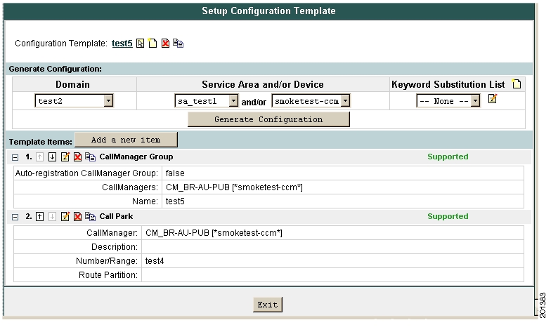
Figure 5-3 displays an example of a Cisco Unified CallManager Configuration Template.

Figure 5-3 Cisco Unified CallManager Configuration Template

Table 5-8 Infrastructure Data Objects 

Infrastructure Data Object
Cisco Unified CallManager Release
4.0.1
4.1.x
4.2.x
5.0.x

Call park

Y

Y

Y

Y

Call pickup group

Y

Y

Y

Y

Call search space

Y

Y

Y

Y

CallManager group

Y

Y

Y

Y

H323 gateway

Y

Y

Y

Y

Hunt list

Y

Y

Y

Y

Hunt pilot

N

Y

Y

Y

Line group

N

Y

Y

Y

Location

Y

Y

Y

Y

Media resource group

Y

Y

Y

Y

Media resource list

Y

Y

Y

Y

Route group

Y

Y

Y

Y

Route list

Y

Y

Y

Y

Route partition

Y

Y

Y

Y

Route pattern

Y

Y

Y

Y

Translation pattern

Y

Y

Y

Y

Voice device group

Y

Y

Y

Y

Voicemail pilot

Y

Y

Y

Y

Voicemail profile

N

N

Y

Y

Voice region

Y

Y

Y

Y


Table 5-9 through Table 5-25 describe the fields for each infrastructure data object of the Provisioning Manager Configuration Templates.


Note Many of the infrastructure data object fields allow you to add items to the lists and let you move the items up and down in the lists. For information on these operations, see the following:

Adding Items to Lists

Changing the Order of Items


Table 5-9 CallManager Group Infrastructure Data Object Fields 

Field
Description

Name

Name.

Available CallManagers

List of available Cisco Unified CallManagers.

Auto-Registration CallManager Group

Select Yes if you want this Cisco Unified CallManager group to be the default Cisco Unified CallManager group when auto-registration is enabled.


Table 5-10 Call Park Group Infrastructure Data Object Fields 

Field
Description

Number/Range

Enter the call park extension number or a range of numbers.

Description

Optional description.

Route Partition

List of available route partitions.

CallManager

List of available Cisco Unified CallManagers.


Table 5-11 Call Pickup Group Infrastructure Data Object Fields 

Field
Description

Name

Name.

Number

Unique directory number (integers).

Description

Optional description.

Route Partition

List of available route partitions.

Available Member Call Pickup Groups

List of available Call Pickup Groups.


Table 5-12 Call Search Space Infrastructure Data Object Fields 

Field
Description

Name

Name.

Description

Optional description.

Available Route Partitions

List of available route partitions. The route partitions list is not strictly required, but you should provide at least one value. You must reference a route partition that already exists on the Cisco Unified CallManager, or define one in the same Configuration Template prior to this call search space.


Table 5-13 H323 Gateway Infrastructure Data Object Fields 

Field
Description

Name

Device name.

Description

Optional description.

Device Pool

List of available device pools. The device pool specifies a collection of properties for this device including CallManager Group, Date/Time Group, Region, and Calling Search Space for auto-registration of devices.

Call Classification

Determines whether an incoming call that is using this gateway is considered off the network (OffNet) or on the network (OnNet).

Media Resource Group List

Provides a prioritized grouping of media resource groups.

Location

Location for this device.

Media Termination Point Required

If Media Termination Point is used to implement features that H.323 does not support (such as hold and transfer), select Yes.

Retry Video Call As Audio

Applies to video endpoints that receive calls.

Wait for Far End H.245 Terminal Capability Set

Specifies that Cisco Unified CallManager needs to receive the far-end H.245 Terminal Capability Set before it sends its H.245 Terminal Capability Set.

MLPP Domain

Multilevel Precedence and Preemption (MLPP) Domain to associate with this device.

Significant Digits Value

Represents the number of final digits that are retained on inbound calls.

Calling Search Spaces

Specifies the collection of Route Partitions that are searched to determine how a collected (originating) number should be routed.

AAR Calling Search Space

Specifies the collection of route partitions that are searched to determine how to route a collected (originating) number that is otherwise blocked due to insufficient bandwidth.

Prefix DN

The prefix digits that are appended to the called party number on incoming calls.

Redirecting Number IE Delivery - Inbound

Selecting Yes accepts the Redirecting Number IE in the incoming SETUP message to the Cisco Unified CallManager.

Calling Party Selection

Any outbound call on a gateway can send directory number information. Choose which directory number is sent.

Calling Party Presentation

Choose whether you want the Cisco Unified CallManager to allow or restrict the display of the calling party phone number.

Called Party IE Number Type Unknown

Choose the format for the number type in called party directory numbers.

Calling Party IE Number Type Unknown

Choose the format for the number type in calling party directory numbers.

Called Numbering Plan

Choose the format for the numbering plan in called party directory numbers.

Calling Numbering Plan

Choose the format for the numbering plan in calling party directory numbers.

Caller ID DN

Enter the pattern that you want to use for calling line ID, from 0 to 24 digits.

Display IE Delivery

Enables delivery of the display IE in SETUP, CONNECT, and NOTIFY messages for the calling and called party name delivery service.

Redirecting Number IE Delivery - Outbound

Includes the Redirecting Number IE in the outgoing SETUP message from the Cisco Unified CallManager to indicate the first redirecting number and the redirecting reason of the call when the call is forwarded.

Packet Capture Mode

Configure this field if you need to troubleshoot encrypted signaling information for the H.323 gateway.

Packet Capture Duration

Configure this field if you need to troubleshoot encrypted signaling information for the H.323 gateway.

SRTP Allowed

Select Yes if you want Cisco Unified CallManager to allow secure and nonsecure calls over the gateway.

Version Stamp

Not used

CTI

Not used.


Table 5-14 Hunt Pilot Infrastructure Data Object Fields 

Field
Description

Pattern

The hunt pilot, including numbers and wildcards (do not use spaces).

Route Partition

If you want to use a partition to restrict access to the hunt pilot, choose the desired partition.

Description

Optional description.

Numbering Plan

Choose a numbering plan.

Route Filter

If your hunt pilot includes the @ wildcard, you may choose a route filter.

MLPP Precedence

MLPP precedence setting.

Hunt List

Choose the hunt list for which you are adding a hunt pilot.

Urgent Priority

Select Yes to interrupt interdigit timing when Cisco Unified CallManager must route a call immediately.

Block Enabled

Enable or disable block.

Release Cause

Dependant on the Block Enabled field. If a release cause is selected, then Block Enabled must be set to True.

Use Calling Party's External Phone Number Mask

Select Yes if you want the full, external phone number to be used for calling line identification (CLID) on outgoing calls.

Calling Party Transformation Mask

Enter a transformation mask value.

Calling Party Prefix Digits (Outgoing Calls)

Enter the prefix digits.

Calling Line Presentation

Used as a supplementary service to allow or restrict the originating caller's phone number on a call-by-call basis.

Calling Name Presentation

Used as a supplementary service to allow or restrict the originating caller's name on a call-by-call basis.

Connected Line Presentation

Used as a supplementary service to allow or restrict the called party's phone number on a call-by-call basis.

Connected Name Presentation

Used as a supplementary service to allow or restrict the called party's name on a call-by-call basis.

Called Party Discard Digits

Select the discard digits instructions that you want to associate with this hunt pilot.

Called Party Transformation Mask

Enter a transformation mask value.

Called Party Prefix Digits (Outgoing Calls)

Enter the prefix digits.


Table 5-15 Line Group Infrastructure Data Object Fields 

Field
Description

Name

Name.

RNA Reversion Timeout

Enter a time, in seconds, after which Cisco Unified CallManager will distribute a call to the next available or idle member of this line group or to the next line group if the call is not answered and if the first hunt option, "Try next member; then, try next group in Hunt List" is chosen.

Distribution Algorithm

Select a distribution algorithm, which applies at the line group level.

Hunt Algorithm No Answer

For a given distribution algorithm, select a hunt option for Cisco Unified CallManager to use if a call is distributed to a member of a line group that does not answer.

Hunt Algorithm Busy

For a given distribution algorithm, select a hunt option for Cisco Unified CallManager to use if a call is distributed to a member of a line group that is busy.

Hunt Algorithm Not Available

For a given distribution algorithm, select a hunt option for Cisco Unified CallManager to use if a call is distributed to a member of a line group that is not available.

Directory Numbers

Enter Directory numbers. This must be a Directory Number that already exist in Provisioning Manager.


Table 5-16 Location Infrastructure Data Object Fields 

Field
Description

Name

Name.

Audio Kilobits

Enter the maximum amount of audio bandwidth (in kbps) that is available for all audio calls on the link between this location and other locations.

Video Kilobits

Enter the maximum amount of video bandwidth (in kbps) that is available for all video calls on the link between this location and other locations. Use 0 for Unlimited and -1 for None.


Table 5-17 Media Resource Group Infrastructure Data Object Fields 

Field
Description

Name

Name.

Description

Optional description.

Available Devices

The available media resources that can be selected.

Is Multicast for MOH Audio

Click Yes to use multicast for Music On Hold Audio.


Table 5-18 Media Resource List Infrastructure Data Object Fields 

Field
Description

Name

Name.

Description

Optional description.

Clause

Not Used.

Available Media Resource Group Names

The available media resource groups that can be selected.


Table 5-19 Route Group Infrastructure Data Object Fields 

Field
Description

Name

Name.

Available Members

The available devices that can be chosen.

Ports

If the device supports individually configurable ports, choose the port.


Table 5-20 Route Partition Infrastructure Data Object Fields 

Field
Description

Name

Name.

Description

Optional description.


Table 5-21 Route Pattern Infrastructure Data Object Fields 

Field
Description

Pattern

The route pattern, including numbers and wildcards. Must be a valid route pattern.

Route Partition

If you want to use a partition to restrict access to the route pattern, select the desired partition.

Description

Optional description.

Numbering Plan

Numbering plan. The default setting is NANP.

Route Filter

If your route pattern includes the @ wildcard, you may choose a route filter.

MLPP Precedence

MLPP precedence setting.

Gateway or Route List

Choose the gateway or route list for which you are adding a route pattern.

Is Gateway Destination Type Gateway

Indicates whether the destination device is a gateway.

Urgent Priority

If Yes is selected, the interdigit timing is interrupted when Cisco Unified CallManager must route a call immediately.

Block Enabled

Enables or disables block.

Release Cause

Dependant on the Block Enabled field. If a release cause is selected, then Block Enabled must be set to True.

Call Classification

Indicates whether the call that is routed through this route pattern is considered either off (OffNet) or on (OnNet) the local network.

Allow Device Override

If Yes is selected, the system uses the Call Classification setting that is configured on the associated gateway or trunk to consider the outgoing call as OffNet or OnNet.

Provide Outside Dial Tone

If Yes is selected, outside dial tone is provided.

Use Calling Party's External Phone Number Mask

Select Yes if you want the full, external phone number to be used for calling line identification (CLID) on outgoing calls.

Calling Party Transformation Mask

Transformation mask value.

Calling Party Prefix Digits (Outgoing Calls)

Prefix digits.

Calling Line ID Presentation

Determines whether you want Cisco Unified CallManager to allow or restrict the display of the calling party's phone number on the called party's phone display for this route pattern.

Calling Name Presentation

Determines whether you want the Cisco Unified CallManager to allow or restrict the display of the calling party's name on the called party's phone display for this route pattern.

Connected Line ID Presentation

Determines whether you want Cisco Unified CallManager to allow or restrict the display of the connected party's phone number on the calling party's phone display for this route pattern.

Connected Name Presentation

Determines whether you want Cisco Unified CallManager to allow or restrict the display of the connected party's name on the calling party's phone display for this route pattern.

Called Party Discard Digits (Outgoing Calls)

Determines the discard digits instructions that you want to associate with this route pattern.

Called Party Transformation Mask

Transformation mask value.

Called Party Prefix Digits (Outgoing Calls)

Prefix digits.


Table 5-22 Translation Pattern Infrastructure Data Object Fields 

Field
Description

Translation Pattern

Translation pattern, including numbers and wildcards.

Route Partition

Available route partitions.

Description

Optional description.

Dial Plan

Numbering plan.

Route Filter

Optional route filter.

MLPP Precedence

MLPP precedence settings.

Call Search Space

Available calling search spaces.

Block Enabled

Enables or disables block.

Release Cause

Dependant on the Block Enabled field. If a release cause is selected, then Block Enabled must be set to True.

Use Calling Party Transform Mask

Determines whether or not to use the calling party's transformation mask.

Calling Party Transform Mask

Transformation mask value.

Calling Party Prefix Digits (Outgoing Calls)

Prefix digits.

Calling Line ID Presentation

Determines whether you want Cisco Unified CallManager to allow or restrict the display of the calling party's phone number on the called party's phone display for this translation pattern.

Calling Name Presentation

Determines whether you want Cisco Unified CallManager to allow or restrict the display of the calling party's name on the called party's phone display for this translation pattern.

Connected Line ID Presentation

Determines whether you want Cisco Unified CallManager to allow or restrict the display of the connected party's phone number on the calling party's phone display for this translation pattern.

Connected Name Presentation

Determines whether you want Cisco Unified CallManager to allow or restrict the display of the connected party's name on the calling party's phone display for this translation pattern.

Called Party Discard Digits

The discard digits instructions that you want to be associated with this translation pattern.

Called Party Transform Mask

Transformation mask value.

Called Party Prefix Digits (Outgoing Calls)

Prefix digits.


Table 5-23 Voicemail Pilot Infrastructure Data Object Fields 

Field
Description

Number

Voicemail pilot number.

Description

Optional description.

Calling Search Space

Available calling search spaces.

Is Default

Indicates whether this pilot number is the default Voice Mail Pilot for the system.


Table 5-24 Voicemail Profile Infrastructure Data Object Fields 

Field
Description

Name

Name.

Description

Optional description.

Voicemail Pilot

Available voicemail pilots.

Voicemail Box Mask

The mask that is used to format the voice mailbox number for auto-registered phones.

Is Default

Indicates whether this voicemail profile is the default for the system.


Table 5-25 Voice Region Infrastructure Data Object Fields 

Field
Description

Name

Name.

Default Codec

Codec setting.

Note For Cisco Unified CallManager 4.1 and earlier, the Default Codec field is set to G.711 no matter what selection is made. For later versions of Cisco Unified CallManager the value is set to the option selected.


Creating Configuration Templates


Step 1 Select Infrastructure Configuration > Provisioning Network > Configuration Templates. The View Configuration Template page appears.

Step 2 Click the New icon (). A prompt appears.

Step 3 Enter a name for the Configuration Template, then click OK. The Set up Configuration Template page appears. Now you can add items to the template (see Adding Items to a Configuration Template).


Adding Items to a Configuration Template

This section describes how to add items to a Configuration Template. The items that you add can be either individual objects or existing Configuration Templates.

You can specify unique names for these infrastructure objects based on the Domain and/or Service Area that they belong to by incorporating the variables DOMAIN and SERVICEAREA in the infrastructure object names. When the Configuration Template is pushed, Provisioning Manager replaces DOMAIN and SERVICEAREA with the name of the Domain and Service Area, respectively, so that new objects are automatically assigned unique names. This provides the infrastructure elements required for Provisioning Manager partitioning on Cisco Unified CallManager, Cisco Unified CallManager Express, or Cisco Unity Express.

Configuration is performed in the order that is defined in the Configuration Template. The same dependencies exist for configuring these objects automatically that exist for configuring them manually. Therefore you must ensure that objects are defined in the Configuration Template in the appropriate order. For more information regarding these dependencies and other requirements, refer to the appropriate Cisco Unified CallManager, Cisco Unified CallManager Express, or Cisco Unity Express documentation.


Note Many of the infrastructure data object fields allow you to add items to the lists and let you move the items up and down in the lists. For information on these operations, see the following:

Adding Items to Lists

Changing the Order of Items


Step 1 Open the Set up Configuration Template page (see Creating Configuration Templates).

Step 2 Click the Choose an Existing Configuration Template icon (). The Choose a Configuration dialog box appears.

Step 3 Click the desired Configuration Template. The template appears.

Step 4 Click Add a new item. The Add a Configuration Template Item page appears.

Step 5 In the Add field, do one of the following:

If you want to create a new item, click New Item and go to Step 6.

If you want to add an existing Configuration Template to this template, click Existing Configuration Template then complete the following:

a. In the page that appears, select the desired Configuration Template.

b. Click Save. The Configuration Template is added.

c. Go to Step 7.

Step 6 In the Device Type field, select a device type. Your options are Cisco Unified CallManager, Cisco Unified CallManager Express, or Cisco Unity Express.

If you select either CallManager Express or Unity Express, the Commands field appears. Do the following:

a. Enter the appropriate Cisco IOS commands.


Note Cisco IOS commands are applied to the device in Configuration Terminal mode. If your device requires you to enter any submodule mode commands, you must enter the commands to enter and exit the submodule modes. Also, Provisioning Manager does not check the syntax of your commands.


b. Click Save. The item is added to the Configuration Template.

If you select CallManager, do the following:

a. In the Item Type list, select an infrastructure data object. The screen refreshes, displaying the options for the object selected. The options will very depending on the object selected (for descriptions of the fields for each infrastructure data object, see Table 5-9 through Table 5-25).

b. Complete the fields as required. If any drop-down list does not contain an item that you require, see Adding Items to Lists.

c. Click Save. The item is added to the Configuration Template.

Step 7 You can do one or more of the following:

Add another item to the Configuration Template; go to Step 4 of this procedure.

Change the order of the items in the Configuration Template (see Changing the Order of Items).

Create a copy of an item in the Configuration Template (see Creating Copies of Items).

Exit from the Configuration Template; click Exit.


Working with Keyword Substitution

If you are creating Configuration Templates that use the same defined parameter multiple times, you can set up a keyword substitution to simplify the process. Keyword substitution allows you to create a string, and wherever that string appears in a Configuration Template, it is replaced by the value that is associated with it.

Adding a Keyword


Step 1 Open the Set up Configuration Template page (see Creating Configuration Templates).

Step 2 Do one of the following:

If you want to add a keyword to a new list, click the New icon () next to Keyword Substitution List.

A new keyword list is created.

If you want to add a keyword to an existing list, select the list, then click the Edit icon ().

The Keyword List page appears. You can change the keyword list name by clicking the name of the list and in the dialog box that opens, enter a new name, then click OK.

Step 3 Enter a string in the Keyword field. The string must start with a dollar sign ($).


Tip It is also recommended that you place brackets {} around the variable. Keyword replacement fails if additional characters are added to the end of the keyword. The brackets prevent you from mistakenly placing characters at the end of the keyword.


The string should look like the following:

${Region}

Step 4 Enter a corresponding value in the Value field. For an example, enter San Jose.

Step 5 Click Update.

Step 6 Click Done.

Now, in this example, whenever you enter the string $(Region), the value San Jose will be substituted for the string.


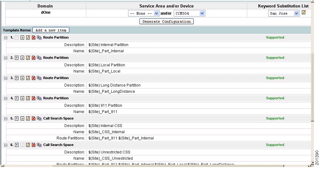
Figure 5-4 shows an example of a Configuration Template that uses keyword substitution. This example creates route partitions and call search spaces with keywords, with a keyword list named San Jose that has one keyword (Site = SJ).

Figure 5-4 Configuration Template Using Keyword Substitution

Editing a Keyword


Step 1 Open the Set up Configuration Template page (see Creating Configuration Templates).

Step 2 In the Keyword Substitution List field, select the keyword list that contains the keyword that you want to edit.

Step 3 Click the Edit icon (). The Keyword List page appears.

Step 4 Change the value as needed.

Step 5 Click Update.

Step 6 Click Done.


Deleting a Keyword


Step 1 Open the Set up Configuration Template page (see Creating Configuration Templates).

Step 2 In the Keyword Substitution List field, select the keyword list that contains the keyword that you want to delete.

Step 3 Click the Edit icon (). The Keyword List page appears.

Step 4 Select the box in the Remove column for the keyword you want to delete.

Step 5 Click Update.

Step 6 Click Done.


Deleting a Keyword List


Step 1 Open the Set up Configuration Template page (see Creating Configuration Templates).

Step 2 In the Keyword Substitution List field, select the keyword list that you want to delete.

Step 3 Click the Edit icon (). The Keyword List page appears.

Step 4 Click the Delete icon ().

Step 5 In the confirmation box, click OK.


Updating an Existing Template


Step 1 Select Infrastructure Configuration > Provisioning Network > Configuration Templates. The Set up Configuration Template page appears.

Step 2 Click the Chooser icon (). The Choose a Configuration Template dialog box appears.

Step 3 Select the Configuration Template that you require. The Set up Configuration Template page appears with the information for the template displayed.

Step 4 Update the information as required.


Adding Items to Lists

The lists in the infrastructure data object fields display the items that already exist on the Cisco Unified CallManagers only. You can also define items in a Configuration Template that are created when the Configuration Template is pushed. The new items will only exist ounce the Configuration Template is pushed. These items may be requirements for other items in the same Configuration Template.

For this reason, Provisioning Manager provides the ability to manually add options to the lists. For example, you can define a route partition and a call search space in the same Configuration Template. To define the call search space item in the Configuration Template, you must specify a route partition, but the route partition will not appear as an option in the Configuration Template because it has not been created.

This procedure demonstrates how you could add the name of the route partition to the list in the Configuration Template for the call search space.


Step 1 In the Add a Configuration Template page (see Updating an Existing Template), click the "+" beside the list. A prompt appears.

Step 2 Enter a name for the option, then click OK. The option appears in the list.


Changing the Order of Items

The order of items in a Configuration Template defines the order that they will be auto-configured in when the template is pushed. By clicking the up and down arrows beside the item number, you can change the order of the following:

Template items.

Items in infrastructure data object fields—Not all items can be reordered. If the items in a field can be reordered, up and down arrows appear next to the field.

Changing the Order of Template Items


Step 1 In the Set up Configuration Template page (see Updating an Existing Template), click the Up or Down arrow beside the appropriate item. The item is moved.


Changing the Order of Items in the Infrastructure Data Object Fields


Step 1 In the Add a Configuration Template page (see Updating an Existing Template), select the item to move.


Note The item must reside in a reorderable infrastructure data object field.


Step 2 Click the up or down arrows beside the field. The item is moved.


Editing Items

You can edit an item after it is added to a Configuration Template.


Step 1 In the Set up Configuration Template page (see Updating an Existing Template), click the Edit icon () for the item you want to edit. The Edit a Configuration Template Item page appears.

Step 2 Make the appropriate changes.

Step 3 Click Update.


Creating Copies of Items

You can create a duplicate of a template item on a Configuration Template and then edit it. This allows you to create multiple versions of the same item.


Step 1 In the Set up Configuration Template page (see Updating an Existing Template), click the Copy icon () for the item you want to copy.

A copy of the item is added to the Configuration Template. You can edit the copy as required.


Deleting Items

You can delete items from a Configuration Template.


Step 1 In the Set up Configuration Template page (see Updating an Existing Template), click the Delete icon () beside the item that you want to delete.

A message appears, asking you to confirm.

Step 2 Click OK. The item is deleted.


Renaming Configuration Templates


Step 1 In the Set up Configuration Template page (see Updating an Existing Template), click the Configuration Template name. A dialog box appears.

Step 2 Type the new name and then click OK. The name is changed.


Creating Copies of Configuration Templates

You can create a copy of an entire Configuration Template and then edit it as required.


Step 1 In the Set up Configuration Template page (see Updating an Existing Template), click the Copy icon () beside the Configuration Template name.

A copy of the Configuration Template is created with _copy added to the name.

Step 2 Rename and edit the Configuration Template as required.


Deleting Configuration Templates

You can delete Configuration Templates.


Step 1 In the Set up Configuration Template page (see Updating an Existing Template), click the Delete icon () beside the Configuration Template name. A message appears, asking you to confirm.

Step 2 Click OK. The Configuration Template is deleted.


Generating a Configuration Using a Template

You apply Configuration Templates by pushing them to the appropriate Domain, Service Area, and/or device.


Step 1 Open the Set up Configuration Template page (see Updating an Existing Template) for the template.

Step 2 Select a Domain. The Service Areas and devices lists are populated with the Service Areas and devices that belong to the selected Domain.

Step 3 Select a Service Area and/or device. Selecting a Service Area updates the device list, only showing devices that belong to the selected Service Area.


Note After selecting a Service Area or device, each template item displays Supported or Unsupported. If an item is unsupported, it is not a valid template item for the device selected or devices in the Service Area. The template item will not be added to the generated template.


Step 4 (Optional) select Keyword List. This is only required if the template contains keywords.

Step 5 Click Generate Configuration. A message appears, asking you to confirm.

Step 6 Click OK. The configuration is generated and the Batch Project page appears. For information on scheduling the provisioning of the configuration, see Working with Batch Projects.


Using Batch Provisioning

Provisioning Manager enables you to create users and provision their services automatically through batch provisioning. Batch provisioning enables you to easily roll out a new office, or transition from legacy systems.

To complete batch provisioning, you must do the following:

1. Create a spreadsheet of users and the services to be provisioned (this typically includes phones and lines), then convert the spreadsheet to a tab-delimited text file called a batch action file.

2. Upload the batch action file into a Provisioning Manager batch project.

3. Run the batch project or schedule it to run later. Provisioning Manager creates the users and provisions the lines and phones based on the data in the file.

You can also view a list of scheduled projects, and the details of the projects that are in progress.

Creating Batch Action Files

Batch action files must contain a single row of column headers. The data columns can be in any order, but must be in a tab-delimited text file. You can compile the data in any text editor, provided that the resulting file conforms to these guidelines. For example, you can create batch files in Microsoft Excel and then export them as tab-delimited files.

Provisioning Manager provides sample files that contain most of the commonly used actions. The sample files are located in the <Installation Directory>/sep/ipt/config/sample/batchProvisioning folder.


Note In addition to the data in the sample files, any provisioning attributes can be included as a column heading and provisioned in a batch file. For information on provisioning attributes, see Configuring Provisioning Attributes, page 6-13.


Required Columns

Table 5-26 describes the columns that are required for every batch action file.

Table 5-26 Batch Action File Required Columns 

Column
Description

Order Type

The order type. Valid options are:

Add

Cancel

Change (change only applies for phones)

User ID

Provisioning Manager user ID to provision the order for.

Product Name

The product name. Note that the input varies depending on the order type:

Add orders—Must be an orderable product (including bundles), but cannot be a subtype (for example, you would use "Phone" instead of "Cisco 7960").

Cancel—Can be any product name that appears in the user's subscriber record. Note that this does not include bundles. Dependent objects are automatically deleted when their parent is deleted.

Change—Phone.

Service Area

Name of the Service Area to order against.


Table 5-27 lists the additional columns that are required when new users are being created.

Table 5-27 Batch Action File Columns for New Users 

Column
Description

First Name

User's first name.

Last Name

User's last name.

Domain

(Optional) Domain to place the new user in.

Phone Number

(Optional) Phone number for the new user.

Email

(Optional) Email address for the new user.

Department

(Optional) Department for the new user.


Guidelines for Creating Batch Action Files


Note Sample batch files are provided for you. They are located on the Provisioning Manager system in the <installation directory>/sep/ipt/config/sample/batchProvisioning folder. You can add additional columns to the sample batch files as required.


When creating batch action files, keep in mind the following guidelines:

If you want the users that will be created to have self-care accounts, you must enable the CreateSelfCareAccounts rule for all applicable Domains.

If you want to add provisioning attributes to your file, add an additional column for the attribute.

MAC Address is required when ProductName is Phone (or a bundle containing a Phone) and Phone Type is not a virtual phone (for example, CTI Port).

New MAC Address is required when changing phones.

Object Name is required when cancelling products.

Hidden attributes can optionally be over-ridden with a column heading of the matching name.

Cisco Unity devices (Cisco Unity, Cisco Unity Connection, and Cisco Unity Express) do not support all products and services. If the batch action file is configured for a product which is not supported by the device in the specified Service Area, batch provisioning will fail. For a list of supported products and services, see Table 3-2.

Product attributes that require user input during the manual order entry process are required to successfully complete the equivalent order in a batch project. Examples include:

Phone Type—Type of phone (for example, Cisco 7960, Cisco 7912) if ordered product is a Phone or a bundle that contains a Phone.

Line Type—Type of line (for example, Auto-Assigned Line or Chosen Line) if ordered product is a Line or a bundle that contains a Line.

Directory Number—Required when ProductName is Line and Type is Chosen Line. Additionally, ordering a product with a dependency that is not met by the order itself (for example, ordering a single Line) requires a column specifying the dependent object. Examples include:

If the product being ordered has a dependency that is not met by the order itself (for example, a single Line), a column specifying the dependent object is required. Examples include:

SelectedPhone—MAC Address of phone to add the line to.

SelectedLine—Directory number of the line to add voicemail.

SelectedVoicemail—Directory number of the voicemail to add unified messaging to.

SelectedEM_Access—Name of the EM_Access (device profile) to add the EM_Line to.

Bundles that contain more than one instance of a base product (for example, phone service with extra line) require their attributes to be specified with a (1), (2), and so on, at the end of the column name. For example, Line Type(1), Directory Number(1).

Speed dial information can be provided directly or indirectly. If provided directly, the expected format is index=number=label, repeated for each speed dial, semicolon delimited, where index is the position of the speed dial (for example; 1, 4, 5, and so on), number is the phone number, and label is the speed dial name (for example, 1=8675306=Jenny;4=888=Voicemail). Alternatively, speed dials can be provided as one set of fields called Speed Dial n (where n is the speed dial position), and a matching set of fields called Speed Dial n Name.

Sample Batch Action File

The following batch action file changes a SoftPhone (CTIport) and provisioning attributes (AAR Calling Search Space and Calling Search Space):

OrderType     UserID    FirstName    LastName    Domain    ProductName    Phone Type     ServiceArea    Line Type    Address    New MAC Address    Email ID    Display Name    Enable Extension Mobility    AAR Calling Search Space    Calling Search Space

change    joeb    joe    brown    test_domain    Phone    CTI Port     testsa    Auto-Assigned Line    name_4    name_4    joeb    joeb    no    joe_css2    joe_ css2


Note Provisioning attributes (AAR Calling Search Space and Calling Search Space) are just added to the end of the file.


Creating Batch Projects

After you create a batch action file, you must create the batch project that it belongs to. When you upload a batch action file, its contents are converted to batch actions, and the columns that are common to all batch actions in the batch action file are displayed.


Note You must upload batch action files in the correct order according to any dependencies that exist between the batch actions. For more information about these dependencies, see Guidelines for Creating Batch Action Files.


Step 1 Select Infrastructure Configuration > Provisioning Network > Batch Provisioning. The Configure a Batch Project page appears.

Step 2 Click the New icon (). The Create a New Batch Project page appears.

Step 3 Type a name and notes for the batch project and then click Create. The batch project is created.

You can now upload one or more batch action files to the batch project.

Step 4 In the Configure a Batch Project screen, click Upload a Batch Action File. The Upload a Batch Action file page appears.

Step 5 Do one of the following

In the File to Upload field, type the full directory path and file name of the file to be uploaded.

Click Browse and then locate and click the file to be uploaded.

Step 6 Click Add. The file is uploaded and its contents are displayed on the Configure a Batch Project page.

Step 7 You can do one or more of the following:

Upload another batch action file (repeat this procedure).

Run the batch project immediately (see Running a Batch Project).

Schedule the batch project to be run later (see Scheduling or Rescheduling a Batch Project).


Editing Batch Projects

It is currently not possible to edit batch projects or batch action files in Provisioning Manager. Instead, you can update the batch action files manually and then upload them into a new batch project, and delete the batch projects that you no longer require.

Deleting Batch Projects

You can delete batch projects that you no longer require.


Step 1 Select Infrastructure Configuration > Provisioning Network > Batch Provisioning. The Configure a Batch Project page appears.

Step 2 Click the Chooser icon (). The Choose a Batch Project dialog box appears.

Step 3 Select the batch project that you require. The Configure a Batch Project page appears.

Step 4 Click the Delete icon () beside the batch project name. A message appears, asking you to confirm.

Step 5 Click OK. The batch project is deleted.


Working with Batch Projects

You can run a batch project immediately, or schedule it to run at a specific time. You can pause a batch project that is currently running, and then restart it or cancel it. After a project has been scheduled, you can pause it, or cancel it entirely. You can also schedule a project to be paused at a later time, for example, if you want to ensure that a project is paused before a scheduled maintenance down-time.

Running a Batch Project


Step 1 Select Infrastructure Configuration > Provisioning Network > Batch Provisioning. The Configure a Batch Project page appears.

Step 2 Click the Chooser icon (). The Choose a Batch Project dialog box appears.

Step 3 Select the batch project that you require. The Configure a Batch Project page appears.

Step 4 In the Project Schedule pane, next to Project Start Date/Time, click Now. A message appears, asking you to confirm.

Step 5 Click OK. The batch project is started and the status changes to In Progress. (To refresh the screen, click the Refresh icon (). When the batch project has completed, the status changes to Complete.


Scheduling or Rescheduling a Batch Project


Step 1 Select Infrastructure Configuration > Provisioning Network > Batch Provisioning. The Configure a Batch Project page appears.

Step 2 Click the Chooser icon (). The Choose a Batch Project dialog box appears.

Step 3 Select the batch project that you require. The Configure a Batch Project page appears.

Step 4 In the Project Schedule pane, next to Project Start Date/Time, click the Chooser icon (). A message appears, asking you to confirm.

Step 5 Click OK. The Select Date and Time dialog box appears.

Step 6 Specify a date and time, as well as a UTC Offset or Location (if required), and then click Select. A clock icon () appears in the Status section to indicate that the batch project has been scheduled.


Canceling a Batch Project

You can cancel (abort) a batch project that is in progress. Provisioning Manager completes any actions that are in progress, but does not submit any further actions.


Step 1 Select Infrastructure Configuration > Provisioning Network > Batch Provisioning. The Configure a Batch Project page appears.

Step 2 Click the Chooser icon (). The Choose a Batch Project dialog box appears.

Step 3 Select the batch project that you require. The Configure a Batch Project page appears.

Step 4 In the Project Schedule pane, click Abort. A warning message appears, asking you to confirm.

Step 5 Click OK. The batch project is canceled.


Pausing a Batch Project

When you pause a batch project, Provisioning Manager completes actions that are in progress, but does not submit any more.


Step 1 Select Infrastructure Configuration > Provisioning Network > Batch Provisioning. The Configure a Batch Project page appears.

Step 2 Click the Chooser icon (). The Choose a Batch Project dialog box appears.

Step 3 Select the batch project that you require. The Configure a Batch Project page appears.

Step 4 In the Project Schedule pane, next to Project Pause Date/Time, click Pause. A message appears, asking you to confirm.

Step 5 Click OK. A message appears, indicating that the batch project has been paused.

Step 6 Click the Refresh icon (). The status of the project is changed to Paused.

Step 7 You have the following options:

To restart the batch project, click Restart. The batch project is restarted.

To cancel the batch project, click Abort. The batch project is canceled.


Scheduling a Batch Project to Pause

You can schedule a pause in a batch project, for example, if you have scheduled a batch project to start at a later time, but you want to ensure that it stops before a scheduled maintenance down-time.


Step 1 Select Infrastructure Configuration > Provisioning Network > Batch Provisioning. The Configure a Batch Project page appears.

Step 2 Click the Chooser icon (). The Choose a Batch Project dialog box appears.

Step 3 Select the batch project that you require. The Configure a Batch Project page appears.

Step 4 In the Pause Execution section, next to Project Pause Date/Time, click the Chooser icon (). A message appears, asking you to confirm.

Step 5 Click OK. The Select Date and Time dialog box appears.

Step 6 Specify a date and time, as well as a UTC Offset or Location, (if required), and then click Select. A date and time appear next to Pause Execution, to indicate that the batch project has been scheduled to pause.


Canceling a Scheduled Batch Project

You can cancel a scheduled batch project provided that it has not started processing.


Step 1 Select Infrastructure Configuration > Provisioning Network > Batch Provisioning. The Configure a Batch Project page appears.

Step 2 Click the Chooser icon (). The Choose a Batch Project dialog box appears.

Step 3 Select the batch project that you require. The Configure a Batch Project page appears.

Step 4 In the Project Schedule pane, next to Project Start Date/Time, click the Clear icon (). A message appears, asking you to confirm.

Step 5 Click OK. The schedule is cleared.


Canceling a Scheduled Pause for a Batch Project

You can cancel a scheduled pause for a batch project.


Step 1 Select Infrastructure Configuration > Provisioning Network > Batch Provisioning. The Configure a Batch Project page appears.

Step 2 Click the Chooser icon (). The Choose a Batch Project dialog box appears.

Step 3 Select the batch project that you require. The Configure a Batch Project page appears.

Step 4 In the Project Schedule section, click the Clear icon (). A message appears, asking you to confirm.

Step 5 Click OK. The scheduled pause for the batch project is cleared.


Viewing the Current Status of a Batch Project

You can view the status of batch projects that are in progress. As a batch project is being run, Provisioning Manager updates the status of the batch actions. You can identify at a glance the actions that are being processed and their status.


Step 1 Select Infrastructure Configuration > Provisioning Network > Batch Provisioning. The Configure a Batch Project page appears.

Step 2 Click the Chooser icon (). The Choose a Batch Project dialog box appears.


Note To see details of a single running order within a batch project, administrators can also use My Activities (Provisioning Dashboard > Manage Activities > My Activities) to view each order as it is executed in the workflow.


Step 3 Select the batch project that you require. The Configure a Batch Project page appears.

The Batch Project Actions pane displays the status of each batch action project.


Note After a batch project has completed, you can check the Subscriber Records of the users to verify that orders have been processed.


Viewing Batch Project Details

You can view the details of a batch project by viewing the details of the batch project actions.


Step 1 Select Infrastructure Configuration > Provisioning Network > Batch Provisioning. The Configure a Batch Project page appears.

Step 2 Click the Chooser icon (). The Choose a Batch Project dialog box appears.

Step 3 Select the batch project that you require. The Configure a Batch Project page appears.

Step 4 In the Batch Project Actions pane, click View in the details column. The View Batch Action Details page appears. This page displays all configured information for the batch project action.


hometocprevnextglossaryfeedbacksearchhelp

Posted: Thu Mar 15 17:18:38 PDT 2007
All contents are Copyright © 1992--2007 Cisco Systems, Inc. All rights reserved.
Important Notices and Privacy Statement.