|
|

This chapter describes how to use the CiscoWorks Blue Maps applications. Read this chapter before using any of the CiscoWorks Blue Maps applications for the first time. This chapter includes the following major sections:
This section describes how to start and use the RSRB application. These are discussed in the following topics:
Before you begin, verify that your network management system has current data to share with the CiscoWorks Blue Maps applications. Even if the network management system is not running at this time, verify that it has been run recently in automanage mode or that a user has run the discovery process at least once since the last installation of new routers or reconfiguration of existing routers.
You can start the RSRB application either from the workstation system prompt or from a network management system, such as NetView for AIX.
During installation, a default user, "cwblue," is set up for running the application from the system prompt. Log in as the "cwblue" user and then start the application.
The RSRB application and support executables are located in $CWBROOT/rsrb/bin. To start the RSRB application from a system prompt, enter the command shown below:
> runrsrb
The .runrsrb script switches you to the $HOME/.rsrb directory and saves the map files there. When running from a remote machine, you might need to issue the following commands to run RSRB:
> cd $CWVROOT/rsrb/blue
> source runrsrb
From the remote display client, enter the following commands:
> xhost +
Log in to the maps server as cwblue.
Set your display environment variable to display_client:0.
> cd $CWVROOT/rsrb/blue
> source runrsrb
Admin>CW Blue Maps>RSRB
To start the Monitor, Poller, and Trap daemons, from the Admin menu, select Process control... and make sure that the Monitor, Poller, and Trap daemons are in the Started state. If any daemon is Inactive, click it and the click the Start button.
Discovery is the process of querying each device in the network to determine whether it is an RSRB-enabled device. If this is your first time using the RSRB application, select Discover from the RSRB Admin menu. Refer to "Synchronization and Discovery in RSRB and DLSw".
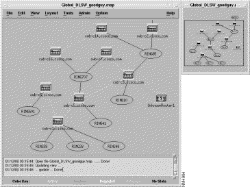
Each map application presents a global (high-level) view of the applicable network devices. This map presents an up-to-date view of virtual rings (displayed as a circle), physical rings (displayed as an oval), pseudorings (displayed as a dotted oval), RSRB-enabled peers and their status, physical links (displayed as solid lines), and RSRB links (displayed as dashed lines). Dashed lines also show connections to non-RSRB rings.
You can change the view by selecting one of the following items from the View menu:
Global---Presents a high-level view of RSRB-enabled Cisco devices. The map presents the status of devices and links.
Refresh---Updates the status of the displayed map immediately.
Locate---Finds a specific device on the map. Select Locate from the View menu and type either the device name or IP address of the device and click Locate. The specified device is selected in the map.
Virtual Ring---Displays information for a specific virtual ring. Select Virtual Ring from the View menu and type the number of the virtual ring you want to investigate, or point to a virtual ring on the map (round), click the right mouse button, and select Virtual Ring. Either action will display all peer relationships and status across the selected virtual ring.
Focus---Displays information for a specific device. Select Focus from the View menu and type the name of a router, or point to a single peer (a router icon), click the right mouse button, and select Focus View. Either action displays the selected peer's perspective of the network, with the in-focus router in a black box. In Focus View, two kinds of statistics are available when you press the right mouse button:
PU or LU--- Lets you display the path to the host for an LU or PU that you specify in the form NAME.SNAdomain and display the routers and rings on which it depends. Alternatively, you can point to a real ring (the oval shape) on the map, click the right mouse button, and select PU List. (The CiscoWorks Blue SNA View product must be installed.)
See the CiscoWorks Blue SNA View Workstation Installation Guide for details about View> LU, View> PU, and PU-LU Info.
There are two methods of locating a specific device on the map.
Here are three ways to select single or multiple devices:
The selected devices can be rediscovered (have the status updated) or can be deleted as a group. For more information about rediscovery, see the section "Performing a Discovery."
The colors and symbols on a map have these meanings:
If a set of devices on any map is not up-to-date because automatic update is disabled or is set to an infrequent interval (and you have not chosen to list target devices in a seed file), you can add and delete devices by hand. From the Edit menu, you can select either Add Device or Delete Device.
When you add or delete a device, RSRB prompts you for the device's host name or IP address and read community string. If the device is found to belong on this map, the application immediately places a new device in its correct position or removes an existing device, depending on the menu item you selected.
If a Cisco device does not appear on the map, but you know that it exists in the network, you can do one of the following:
Use the Layout menu to select various methods of map layout. There are three layout methods:
Circular---Presents network devices in a circular layout
Hierarchical---Presents network devices in a hierarchical layout
Symmetrical---Presents network devices in a symmetrical layout
To save a custom topology for later use, click select the Save As from the File menu and specify a name for the topology. When you re-open the topology file, you will see an exact representation of the saved map. Saving is also done automatically when you switch views or end the application normally.
If the CiscoWorks Blue SNA View product is also installed, you can use the SNA View Task Manager window, which is described in the CiscoWorks Blue SNA View Workstation Installation Guide. To start the SNA View Task Manager, select SNA View Task Mgr from the RSRB Tools menu.
To terminate the RSRB Map application, select Exit from the File menu.
This section describes how to start and use the DLSw application. These are discussed in the following topics:
Before you begin, verify that your Network Management System has current data to share with the CiscoWorks Blue Maps applications. Even if the Network Management System is not running at this time, verify that it has been run recently in Automanage mode or that a user has run the Discovery process at least once since the last installation of new routers or reconfiguration of existing routers.
You can start the DLSw application from the workstation system prompt or from a network management system, such as NetView for AIX.
During installation, a default user, "cwblue," is set up for running the application from the system prompt. Log in as the "cwblue" user and then start the application.
The DLSw application and support executables are located in $CWBROOT/dlsw/bin. To start the DLSw application from a system prompt, enter the command shown below:
> rundlsw
The .rundlsw script switches you to the $HOME/.dlsw directory and saves the map files there. When running from a remote machine, you might need to issue the following commands to run DLSw:
> cd $CWVROOT/dlsw/blue
> source rundlsw
From the remote display client, enter the following commands:
> xhost +
Log in to the maps server as cwblue.
Set your display environment variable to display_client:0.
> cd $CWVROOT/rsrb/blue
> source runrsrb
Admin>CW Blue Maps>DLSW
To start the Monitor and Poller daemons, from the Admin menu, select Process control... and make sure the Monitor and Poller daemons are in the Started state. If either is Inactive, click it and click the Start button.
Discovery is the process of querying each device in the network to determine whether it is a DLSw-enabled device. If this is the first time using the DLSw application, select the Discover item from the Admin menu. For more information on discovering your network, refer to the "Synchronization and Discovery in RSRB and DLSw".
Each map application presents a global (high-level) view of the applicable network devices, as shown in Figure 4-1. This presents an up-to-date map of DLSw-enabled peers and their statuses, plus physical links.
You can change the view by selecting one of the following items from the View menu:
From this view, you can request DLSw information about any router on the map. Point to any router, press and hold the right mouse button, select Information, Statistics, or Circuit List on the popup menu, and release the mouse button.
You can change the view by selecting on of the following items from the View menu:
See the CiscoWorks Blue SNA View Workstation Installation Guide for details about LU, PU, and PU-LU Info.
There are two methods of locating a specific device on the map.
When you have located one or more devices of interest, you can select:
The selected devices can be rediscovered (have the status updated) or can be deleted as a group. For more information about rediscovery, see the section "Performing a Discovery."
Interpret the colors and symbols on a map as follows:
If the set of devices on any map is not up to date, because automatic update is disabled or set to an infrequent interval (and you have not chosen to list target devices in a seed file), you can add and delete devices by hand. From the Edit menu, you can select either Add Device or Delete Device.
When you add or delete a device, the DLSw Maps application prompts you for the device's host name or IP address, and read community string. If the device is found to belong on this map, the application immediately places a new device in its correct position or removes an existing device, depending on the menu item you selected.
If a Cisco device does not appear on the map, but you know it exists in the network, you can:
Use the Layout menu to select various methods of map layout. The layouts are:
To save a custom topology for later use, click select the Save As from the File menu and specify a name for the topology. When you re-open the topology file, you will see an exact representation of the saved map. Saving is also done automatically when you switch views or end the application normally.
If the CiscoWorks Blue SNA View product is also installed, you can use the SNA View Task Manager window, which is described in the CiscoWorks Blue SNA View Workstation Installation Guide. To start the SNA View Task Manager, select SNA View Task Mgr from the DLSw Tools menu.
To terminate the DLSw Map application, select Exit from the File menu.
This section details the concepts of synchronization and discovery, which apply to both the RSRB Maps and DLSw Maps applications and which can help you operate the applications efficiently.
A comment is a single line of text that begins with the # character; comment lines are ignored by RSRB.
Each line in the seed file has this format:
router [ReadCommunityString]
This is a sample seed file:
# Seed file for CiscoWorks Blue Maps applications
north.cisco.com threebears
east.cisco.com goldilocks
172.18.7.47
west.cisco.com
172.18.7.32
172.18.7.144 threebears
You can list the routers in any order.
To use a seed file to provide the information to the RSRB application, perform the following steps.
Step 1 Use a text editor to create the seed file. Save the RSRB seed file in $HOME/.rsrb/rsrbseed
Step 2 Load the seed file into the RSRB Map by starting RSRB and select Discover from the Admin menu. Enter the name of the seed file; discovery takes place while you wait.
Step 3 After loading the database using the seed file, the Map application operates accurately until a router is taken off line or a new router is configured. At that time, you can do one of the following:
To update the maps application database with the network management system database one time, from the Admin menu, select Discover then Database.
This places the routers found by the network management system in the maps database. This process also checks the maps application database for new routers, polls their MIBs, and updates the maps database with the new MIB information.
Step 1 From the Admin menu, select Process Control.
Step 2 Select the Sync process box and click Start.
This places routers found by the network management system in the maps database.
Step 3 Select the Sync process box again to disable it and select the Discover process box and click Start.
This process checks the maps application database for new routers, polls their MIBs, and updates the maps database with the new MIB information.
If you add only one or a few routers to your network, you can discover each router individually by doing the following.
Step 1 From the Edit menu, select Add Device(s).
Step 2 Enter the device name and its read community.
Step 3 Click OK.
This adds the router to the maps database, polls the router's MIB, and adds the MIB information to the maps database.
After you reset the Sync daemon to immediately collect IP addresses from the network management system, the Maps application still must communicate with the network devices to learn whether they are RSRB- or DLSw-enabled devices. There are two ways to perform this discovery:
An APPN Map shows the APPN network topology which is the network nodes and connections between them that make up the backbone of the APPN network. These steps describe how to get the APPN Map application started and how to navigate through its windows and views.
Every APPN network node stores information about the backbone APPN network. At startup, the APPN Map application must access the information stored in any one APPN network node (that supports the APPN Management Information Based) before presenting a network map. The network topology agent is the one node whose network information is used to build the APPN map.
APPN network nodes are named in the form NETID.CPNAME, not by IP address or device name. You can use the optional discovery process to build a correlation of APPN names with IP addresses or device names.
This section describes how to start and use the APPN application. These tasks are discussed in the following topics:
You can start the APPN application either from a network management system, such as NetView for AIX, or from the workstation system prompt.
To start the APPN application from a workstation system prompt, enter these commands:
cd $CWBROOT/appn/bin
runappn [-f devicename [-r read_community_string]]
Where:
-f devicename
-r read_community_string (use in association with -f)
-v displays version information.
To start APPN from NetView for AIX, use this NetView for AIX menu item:
Admin>CW Blue Maps>APPN
If you do not enter any options with the runappn command, the APPN Map application looks in its preferences file, $CWBROOT/etc/appninit, for the Control Point (CP) name (or IP address or device name, and read community string) of an APPN node from which to collect network topology. If the given device is not specified, APPN Map prompts you to identify a network topology agent, as shown in Figure 4-2.
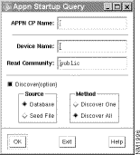
Use the APPN Startup Query window to select a topology agent in one of these ways:
After selecting the topology agent or discovery method, click OK.
To display APPN resources, you must have an APPN network node to act as a network topology agent to collect the information. You can specify a topology agent in one of these ways:
This section describes the APPN discovery process and discusses the following topics:
APPN identifies nodes on the map in the form NETID.CPNAME. To query and collect management data from nodes, however, the application must address them with an IP address. Therefore, the application must correlate APPN names with IP addresses. To build a correlation for all APPN nodes, APPN Map prompts you for an IP address (or device name) and read community string the first time you ever request a view for a particular node. The application maintains the correlation in subsequent sessions.
To avoid being prompted for IP addresses (or names) and read community strings, you can perform a one-time discovery of the entire APPN network. Discovery is the process of querying IP devices in the network to determine if they are APPN network nodes, and, if so, their APPN names.
The APPN Map application stores correlation data in a binary file named $CWBROOT/appn/bin/appnfile. This file is not accessible to the user, but you can delete it to force the application to lose all correlation data.
Another form of discovery is the search of IP devices until a single APPN node is found that can serve as the network topology agent.
You can launch the discovery process two ways, as described below:
The appninit file contains a set of startup parameters for the APPN Map application that can be used to override default values.
APPN Map command line parameters override the parameters specified in an appninit file.
Each user can have a private appninit file. If the APPN Map application cannot find $HOME/.appninit, it reverts to the $CWBROOT/etc/appninit file.
A sample appninit file follows.
# APPN Maps preferences file
# (comments start with # in column 1 and blank lines are OK)
# (keywords must start in column 1, and there must be
# blanks on each side of the = character)

# Selection of the network topology agent is done in this order:
# 1) command line parameters, if any
# 2) nettopoagent and nettopocommstr from this file, if specified.
#backupnettopoagent will be used as a backup, only if nettopoagent
# is specified and not overridden by command line parameter;
# 3) user will be prompted to run discovery or enter agent information

# network topology agent ip address or device name (NOT appn cpname)
#nettopoagentdevname =

# network topology agent read community string
#nettopordcommstr =

# network topology agent APPN control point name (NETID.CPNAME format)
# nettopoagentcpname = NETID.CPNAME

# backup network topology agent ip address or device name (NOT appn cpname)
#backupnettopoagentdevname =

# backup network topology agent read community string
#backupnettopordcommstr =

# backup network topology agent APPN control point name (NETID.CPNAME #format)
# backupnettopoagentcpname = NETID.BACKUP

# default read community string
rdcommstr = public

# automatic collection of local topology (NONE, NN_ONLY, ALL)
autolocaltopo = NN_ONLY

# network topology polling interval, in seconds (no polling = 0)
nettopopoll = 10

# backup network topology polling interval, in seconds (no polling = 0)
# (in backup mode only, when primary agent fails backup uses nettopopoll
backupnettopopoll = 600)

# local topology polling interval, in seconds (no polling = 0),
loctopopoll = 600
# end of preferences file
If you would rather not use the startup dialog box, you can use the appinit file to specify one of the following:
If you specify a network topology agent in the appninit file, you can also specify a backup network topology agent in the appninit file. Specify one of the following:
If a network topology agent is not specified in appninit or in a command line parameter, the application prompts you to identify a network topology agent. If the application is unable to collect network topology from the agent you identify, it retries at the interval specified by nettopopoll in the appninit file.
Because the overhead of network topology polling is less than the overhead of local topology polling, the APPN Map application performs network topology polling more frequently. See the nettopopoll, loctopopoll, and backupnettopopoll parameters in the appninit file.
Local topology is data collected from an APPN node and stored in the application.
The APPN Maps application usually collects local topology data on demand (when the generation of a view requires it). To speed up the generation of some views, and to assure the completeness of adjacent nodes views, set the autolocaltopo parameter to one of the following values:
The record format of the seed file is as follows:
device [ReadCommunityString]
Here is an example:
# Seed file for APPN Map application
#Comment is denoted by the # character
north.cisco.com threebears
south.cisco.com goldilocks
east.cisco.com goldilocks
172.18.7.47
west.cisco.com
172.18.7.32
172.18.7.144 threebears
172.18.7.160
If a read community string is missing, the application uses the rdcommstr parameter from the appninit file. Store an APPN seed file in $CWBROOT/appn/bin/appnseed.
View from APPN menu bar to select the network view.
Select Global from the View menu to display the APPN global map, as shown in Figure 4-3. The global map displays the APPN network topology database as viewed from the network topology agent. It shows the network nodes and virtual routing nodes, and the transmission groups (TGs) between them. TGs are aggregated so that only a single line is shown between two nodes, even if there is more than one TG between the nodes.
Resources are shown with unknown status if the application determines that the network topology agent may not be getting updates about them. This may be due to inactive links or no path of CP-CP sessions to carry the updates.
This view is updated as new information is available from the network topology agent, subject to the polling interval (nettopopoll parameter in the appninit file).
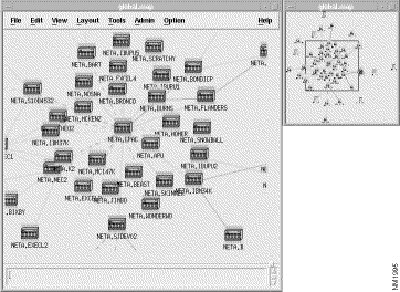
On the global map, point to a connection (a line between nodes) on the map, press the right mouse button, and select one of the following:
From the global APPN map, point to a node, press the right mouse button, and select the Show Adjacent Nodes view.
The Adjacent Nodes view is a subset of the APPN network that is one hop away from the pointed-to node. The Adjacent Nodes view also shows end nodes and LEN nodes connected to any of those neighbors from which the application has already collected topology information. To ensure the generation of complete Adjacent Nodes views, see "Using appninit to Facilitate the Generation of Views."
In the Adjacent Nodes view, note that the available views for a link are the same as for a link in global view.
In the Adjacent Nodes view, point to a node, press the right mouse button, and select the Ports and Links view.
The Ports and Links view, shown in Figure 4-4, is a view of all the logical ports on the pointed-to node, plus the links from those ports to adjacent nodes.
Adjacent nodes shown with names with ?,link=linkname as the NETID indicate that the link is inactive and the adjacent node name is not known. The link name is displayed as the second part of the name. For example, in Figure 4-4 ?,link=.C5 indicates that link C5 is inactive and the destination node name is unknown.
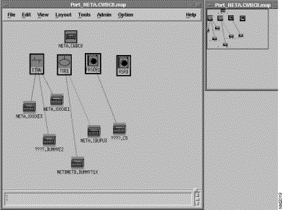
The Ports and Links view can depict the following port types:
There are two methods of locating a specific node on the map. They are as follows:
The colors and symbols on the APPN Map have these meanings:
To save a custom topology for later use, click select the Save As from the File menu and specify a name for the topology. When you re-open the topology file, you will see an exact representation of the saved map. Saving is also done automatically when you switch views or end the application normally.
If the CiscoWorks Blue SNA View product is also installed, you can use the SNA View Task Manager window, which is described in the CiscoWorks Blue SNA View Workstation Installation Guide. To start the SNA View Task Manager, select SNA View Task Mgr from the APPN Tools menu.
To terminate the APPN Map application, select Exit from the File menu.
CiscoWorks Blue Maps includes an HTML interface that you can use to access Maps from a Web browser, such as the Netscape Navigator. This interface provides functions similar to those provided by the standard Motif interface, except that actual maps are not displayed. You can access the Maps HTML interface from either the Maps Tools menu or from any web browser. This section describes these tasks:
Before you access the Maps HTML interface, ensure that the HTTP daemon is running in the workstation where the Maps applications are installed. To start the HTTP daemon, enter one of the following commands at the workstation.
On AIX, Solaris, and HP-UX:
ps -ef | grep httpd
On Sun OS:
ps -aux | grep httpd
If the daemon is not running, you can start it with this command:
$NMSROOT/etc/start_httpd
If you are using a different http server than the one provided by CiscoWorks, then do the following:
Step 1 Locate the srm.conf file for the httpd daemon that you are using. It is in the httpd/conf directory.
Step 2 Search for the DocumentRoot setting in the srm.conf file.
Step 3 Change directory to the directory listed under DocumentRoot.
Step 4 Enter the following command:
ln -s $CWBROOT/htdocs cw-blue
where $CWBROOT is where CiscoWorks Blue Maps is installed, usually /usr/cw-blue.
Step 5 Search for the ScriptAlias setting in the srm.conf file.
Step 6 Change directory to the directory listed as the ScriptAlias for /cgi-bin/.
Step 7 Enter the following command:
ln -s $CWBROOT/cgi-bin cw-blue
where $CWBROOT is where CiscoWorks Blue Maps is installed, usually /usr/cw-blue.
You can access the Maps HTML interface from any web browser in the network using the following URL:
http://workstation_host:/cw-blue/cwblue.html
Where workstation_host is the IP address or host name of the workstation where you installed CiscoWorks Blue Maps. For example, if you installed maps on a workstation with the address kerr.cisco.com, set your browser to:
http://kerr.cisco.com:/cw-blue/cwblue.html
To start the CiscoWorks Web Browser from the Maps application, select Web Browser from the Tools menu.
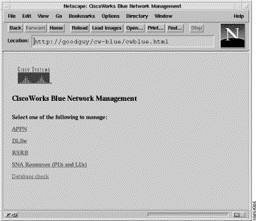
When the browser finds the Maps HTML interface, the main HTML main window is displayed, as shown in Figure 4-5.
 Management HTML Main Window
The five links shown in the window let you access various applications or information, as indicated below.
Select APPN from the HTML main window. The APPN Network Management window is displayed, as shown in Figure 4-6.
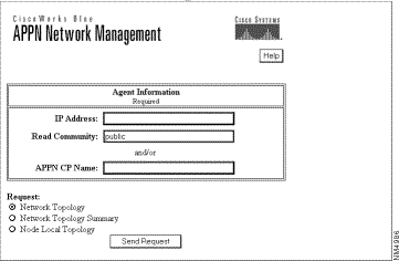
From this window, you can select one of the following:
Network Topology---To show information about the APPN network
Node Local Topology---To show information about a specific APPN router
You then enter one of these:
Then click the Send Request button.
Select DLSw from the HTML main window. The DLSw window is displayed, as shown in Figure 4-7.
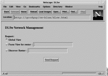
In this window, you have only this one option:
Global View, To show all DLSw routers
Then click the Send Request button.
Select RSRB from the HTML main window. The RSRB window is displayed, as shown in Figure 4-8.
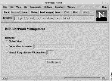
From this window, you can select one of the following:
Global View---To show all RSRB routers.
Focus View for router---To show virtual rings and token rings for a specific RSRB router. Enter the IP address or host name for the router.
Virtual Ring view for VR number---To show all RSRB routers for a specific virtual ring. Enter the virtual ring (VR) number.
Then click the Send Request button.
Select SNA Resources (PUs and LUs) from the HTML main window. The Managing SNA Resources window is displayed, as shown in Figure 4-9.
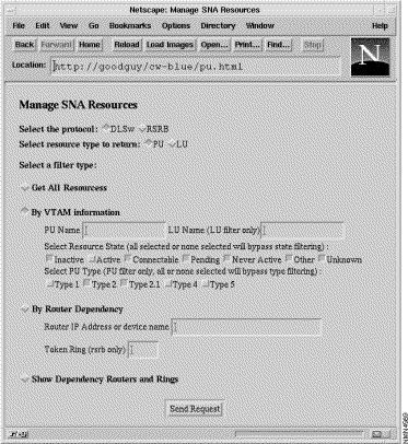
From this window, you can select any of the following:
Get all Resources---To show all LUs and PUs
By VTAM Information---To select the LUs and PUs based on VTAM information
By Router Dependency---To select the LUs and PUs based on the router
Then click the Send Request button.
Select Database Check from the HTML main window. The Database Check window is displayed, as shown in Figure 4-10.
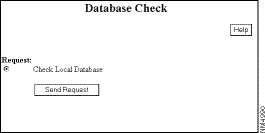
In this window, you have only this one option:
Check Local Database---To check the Sybase database on the workstation
Then select Send Request button.
![]()
![]()
![]()
![]()
![]()
![]()
![]()
![]()
Posted: Thu Aug 19 11:41:41 PDT 1999
Copyright 1989-1999©Cisco Systems Inc.