|
|

Table Of Contents
Configuring Broadband Access Center for Cable
Configuring the Class of Service
Selecting Configuration Options
Gateway (xGCP) Control Protocol Defaults
Adding and Modifying a License
Managing Regional Distribution Unit Extensions
Installing RDU Custom Extension Points
Modifying Publishing Plug-In Settings
Configuring the SRV Record in the Network Registrar DNS Server
Configuring SNMPV3 Cloning on the RDU and DPE for Secure Communication with PacketCable MTAs
Creating the Key Material and Generating the Key
Automatically Generated FQDN Format
Properties for Automatically Generated FQDNs
Sample Automatic FQDN Generation
Configuring Broadband Access Center for Cable
This chapter describes the Broadband Access Center for Cable (BACC) configuration activities that you perform using Configuration menu options:
•
Configuring the Class of Service
•
•
•
Configuring the Class of Service
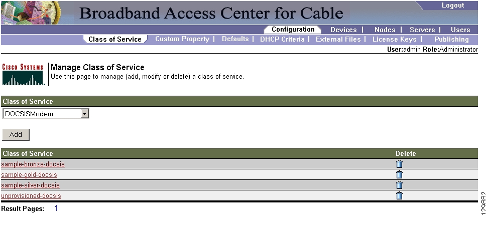
Using the BACC administrator, you can configure the classes of service offered to your customers. For example, you can associate DOCSIS options with different DOCSIS classes of service. You use the BACC administrator user interface to add, modify, view, or delete any selected class of service. Start with the Manage Class of Service page, as shown in Figure 10-1.
Figure 10-1 Manage Class of Service Page
Table 10-1 identifies the fields and buttons shown in Figure 10-1.
Table 10-1 Configure Class of Service Page
Class of Service
A drop-down list that identifies the technology classes of service that you can search for. Available selections, as they appear on screen, include:
•
•
•
•
•
•
•
Note
Add
Lets you add a new class of service.
Class of Service list
Displays the attributes of any selected class of service.
Delete
Lets you delete selected classes of service.
Adding a Class of Service
To add a specific class of service:
Step 1
Step 2
Step 3
Step 4
Step 5
Step 6
For example:
Assume that you want to create a new class of service called Gold-Classic for DOCSIS modems. You might:
a.
b.
c.
d.
Step 7
Step 8
Note
Caution
When adding a PacketCable class of service, you must specify the /cos/packetCableMTA/file property with the value being the name of a previously added external file. This file will be used when provisioning a Packetcable device that has this class of service.
When adding a CableHomeWanMan class of service, you must specify the /cos/cableHomeWanMan/file property with the value being the name of a previously added external file. This file will be used when provisioning a CableHomeWanMan device that has this class of service.
Table 10-2 identifies the fields and buttons shown in the Add Class of Service page.
Modifying a Class of Service
You modify your classes of service by selecting the various properties and assigning appropriate property values. When creating a class of service for the first time you must select all the required properties and assign values to them. If you make a mistake, or your business requirements for a certain class of service change, you can either change the property value before submitting your previous changes or delete the Property Name:Property Value pair altogether.
Note
To add, delete, or modify class of service properties:
Step 1
Step 2
Step 3
Step 4
•
–
–
•
–
–
•
–
–
Note
Step 5
Step 6
Deleting a Class of Service
You can delete any existing Class of Service but, before you attempt to do so, you must ensure that there are no devices associated with that Class of Service.
Tip
If you try to delete a Class of Service with devices associated with it, this error message is displayed:
The following error(s) occurred while processing your request.
Error: Class Of Service [sample-COS] has devices associated with it, unable to delete

Please correct the error(s) and resubmit your request.
The specific class of Service is specified within the error message. In this example this is represented by sample-COS.
To delete a class of service:
Step 1
Step 2
Step 3
Note
Step 4
Note
Configuring Custom Properties
Custom properties let you specify additional customizable device information to be stored in the RDU database. The Custom Property configuration page is found under the Configuration menu and you use this page to add or delete custom properties.
Caution
To configure custom properties:
Step 1
Step 2
•
–
–
–
–
•
–
–
–
Step 3
Configuring Defaults
The Defaults page, found under the Configuration option, lets you access the default settings for the overall system, including the regional distribution unit (RDU), Network Registration extensions, and all supported technologies.
Selecting Configuration Options
The procedure for configuring specific default types is identical. Complete this procedure to access the desired defaults page and then refer to the appropriate section within this chapter for a description of the various page components.
Step 1
Step 2
Step 3
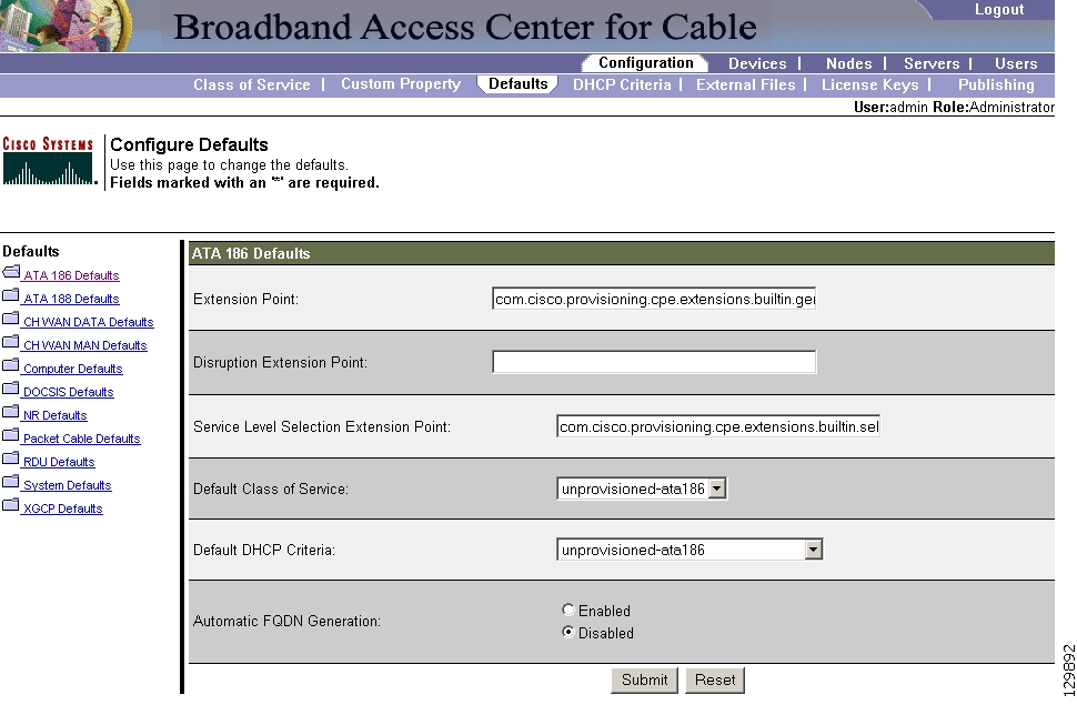
ATA 186 Defaults
The Cisco ATA 186 is a handset-to-Ethernet adaptor that turns a traditional telephone into an Ethernet IP telephone. You can take advantage of the many IP telephony applications by connecting an existing analog telephone to this device.
The Configure ATA 186 Defaults page ( Figure 10-2) displays a list of default values currently available to support the ATA 186.
Figure 10-2 Configure ATA 186 Defaults Page
Table 10-3 identifies the fields and buttons shown in Figure 10-2. In many cases, the parameters that appear on this page also appear in other default pages.
Table 10-3 Configure ATA 186 Defaults Page
Extension Point
Identifies the extension point to execute when generating a configuration for a device of this technology.
Disruption Extension Point
Identifies the extension point to be executed to disrupt a device of this technology.
Service Level Selection Extension Point
Identifies the extension used to determine the DHCP criteria and Class of Service required for a device.
Default Class of Service
Identifies the current default class of service for a specific device technology, in this example, ATA186. New, unrecognized devices of that technology type will be assigned to this class of service. Use the drop-down list to select a new default value.
Default DHCP Criteria
Identifies the current default DHCP criteria for a specific device technology, in this example, ATA186. New, unrecognized devices of that technology type will have this default DHCP criteria assigned. Use the drop-down list to select a new default value.
Automatic FQDN Generation
Automatically generates a host and domain name for the device. Two selectable options are available:
•
•
Note
Submit
Activates the changes you have made. After the administrative database has been updated the Configure Defaults page will reflect the changes you have made.
Reset
Returns all settings to their previous setting.
ATA 188 Defaults
The Cisco ATA 188 interfaces regular telephones with IP-based ethernet telephony networks. The ATA 188 provides true, next-generation voice-over-IP (VoIP) terminations to support the needs of the enterprise, small-office environments, and emerging VoIP managed voice services and local services market.
The Configure ATA 188 Defaults page displays a list of default values currently available to support the ATA 188. The default parameters displayed for the ATA 188 are identical to those displayed for the ATA 186 although the values you select could be different.
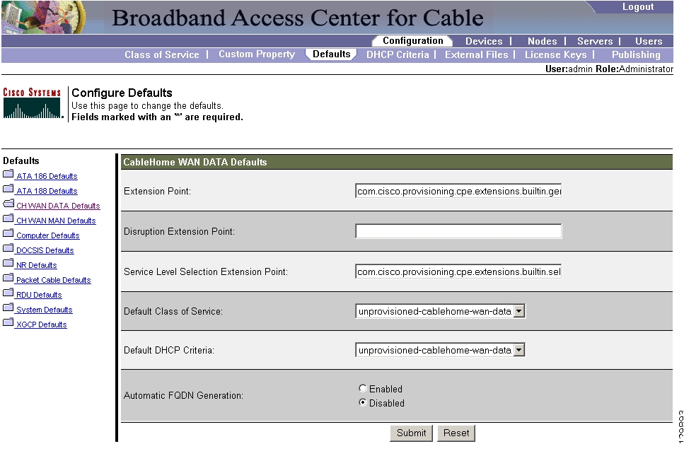
CableHome WAN Defaults
There are two distinct CableHome WAN default screens; one for WAN-Data devices and one for WAN-Man devices.
WAN-Data devices, which are entirely dependent on their corresponding WAN-Man devices, are not unlike computers operating in the promiscuous mode, relative to their cable modems. A WAN-Data device is simply a MAC address and an IP address.
In either case, select the desired default from the displayed list to display the appropriate page. Each WAN default page contains the same fields and buttons, as identified in Table 10-4.
Table 10-4 Configure WAN MAN /WAN Data Defaults Page
Extension Point
Identifies the extension point to execute when generating a configuration for a WAN device.
Disruption Extension Point
Identifies the extension point to be executed to disrupt a WAN device.
Service Level Selection Extension Point
Identifies the extension used to determine the DHCP criteria and Class of Service required for a device.
Default Class of Service
Identifies the current default class of service for a WAN-Data. New, unrecognized WAN devices are assigned to this class of service. Use the drop-down list to select a new default value.
Default DHCP Criteria
Identifies the current default DHCP criteria for a specific device technology. New, unrecognized WAN devices are assigned this default DHCP criteria. Use the drop-down list to select a new default value.
Automatic FQDN Generation
Automatically generates a host and domain name for the device. Two selectable options are available:
•
•
Note
CableHome WAN Data Defaults
When you select the CableHome wide area network (WAN) Data defaults link, the CableHome Defaults page (see Figure 10-3) appears. Use this page to configure the WAN-Data device type.
Figure 10-3 Configure CableHome WAN-Data Defaults Page
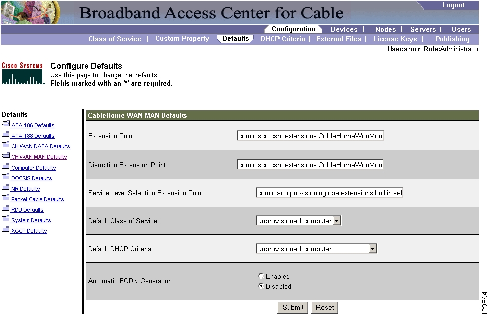
CableHome WAN-Man Defaults
When you select the CableHome WAN-Man defaults link, the CableHome WAN-Man Defaults page (see Figure 10-4) appears. Use this page to configure the WAN-Man device type.
Figure 10-4 Configure CableHome WAN-Man Defaults Page
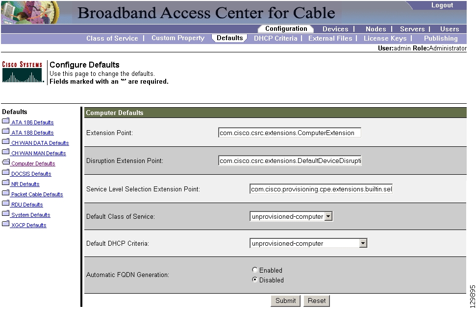
Computer Defaults
The Computer Defaults page ( Figure 10-5) displays a list of default values currently applied to the computers supported by BACC.
Figure 10-5 Configure Computer Defaults Page
Refer to Table 10-3 for the description of all fields and buttons appearing in Figure 10-5.
Note
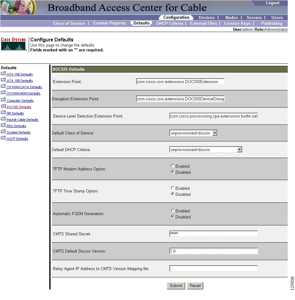
DOCSIS Defaults
When the DOCSIS Defaults option is selected, the DOCSIS Defaults page appears. This page ( Figure 10-6) displays a list of default DOCSIS values currently applied to cable modems supported by BACC.
Figure 10-6 Configure DOCSIS Defaults Page
Refer to Table 10-5 for the description of all fields and buttons appearing in Figure 10-6.
Note
Table 10-5 identifies the fields and buttons that are unique to this defaults page.
Table 10-5 Configure DOCSIS Defaults Page
Extension Point
Identifies the extension point to execute when generating a configuration for a DOCSIS device.
Disruption Extension Point
Identifies the extension point to be executed to disrupt a DOCSIS device.
Service Level Selection Extension Point
Identifies the extension used to determine the DHCP criteria and Class of Service required for a device.
Default Class of Service
Identifies the current default class of service for a device. New, unrecognized devices are assigned to this class of service. Use the drop-down list to select a new default value.
Default DHCP Criteria
Identifies the current default DHCP criteria for a specific device technology. New, unrecognized devices are assigned this default DHCP criteria. Use the drop-down list to select a new default value.
TFTP Modem Address Option
Identifies whether the TFTP modem address option is enabled.
TFTP Time Stamp
Identifies whether the TFTP server will issue a time stamp.
Automatic FQDN Generation
Automatically generates a host and domain name for the device. Two selectable options are available:
•
•
Note
CMTS Shared Secret
Identifies the character string that BACC uses in the calculation of the CMTS MIC in the configuration file. The CMTS uses it to authenticate the configuration file that a cable modem submits to the CMTS for authorization.
CMTS Default Docsis Version
Specifies the default DOCSIS version used by all CMTSs. If you do not enter a DOCSIS version in this field, it will default to version 1.0.
Relay Agent IP Address to CMTS Version Mapping file
Identifies the mapping file used by the CMTS. This file specifies the DOCSIS version that the CMTS will use.
Note
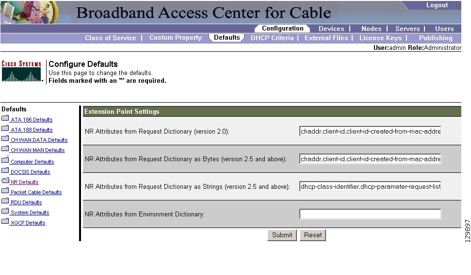
Network Registrar Defaults
BACC provides Network Registrar (NR) extension points that allow BACC to pull information from an incoming DHCP packet(s) to detect a device's technology. They also let BACC respond to device DHCP requests with options that correspond to the configuration stored at the DPE.
When the NR Defaults option is selected, the NR Defaults page (see Figure 10-7) appears.
Figure 10-7 Configure Network Registrar Defaults Page
Refer to Table 10-6 for the description of all fields and buttons appearing in Figure 10-7.
Note
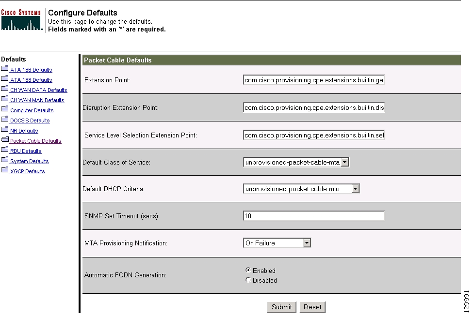
PacketCable Defaults
The PacketCable Defaults page identifies those defaults necessary to support the PacketCable voice technology. When selected the PacketCable Defaults page (see Figure 10-8) appears.
Figure 10-8 Configure PacketCable (Voice Technology) Defaults Page
Table 10-7 identifies the fields and buttons that are unique to this defaults page.
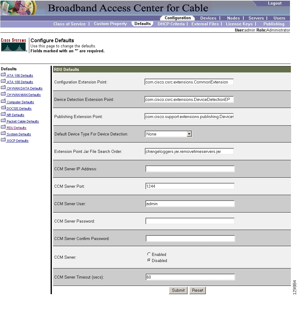
RDU Defaults
When you select the RDU defaults link, the RDU Defaults page (see Figure 10-9) appears. Use this page to configure the RDU to communicate with Network Registrar. See the Cisco CNS Network Registrar User's Guide for additional information.
Figure 10-9 Configure RDU Defaults Page
Table 10-8 describes all fields and buttons appearing in Figure 10-9.
Note
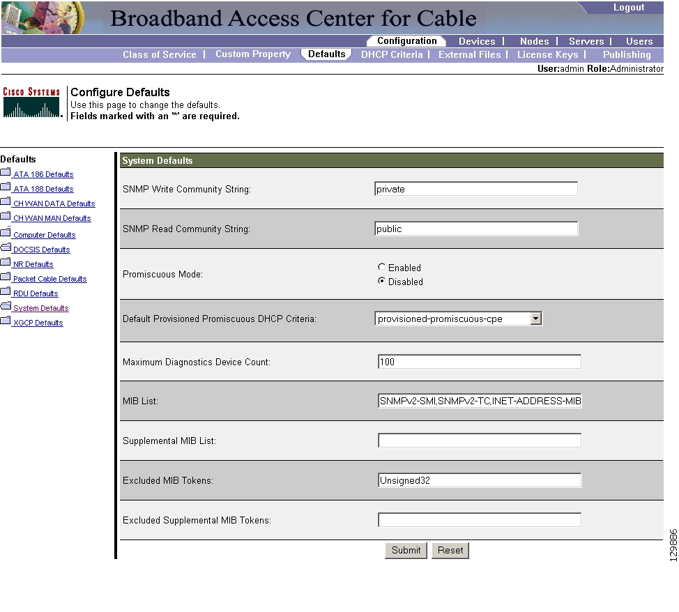
System Defaults
When you select the Systems Defaults link, the System Defaults page (see Figure 10-10) appears.
Figure 10-10 System Defaults Page
Note
Table 10-9 describes all fields and buttons appearing in Figure 10-10.
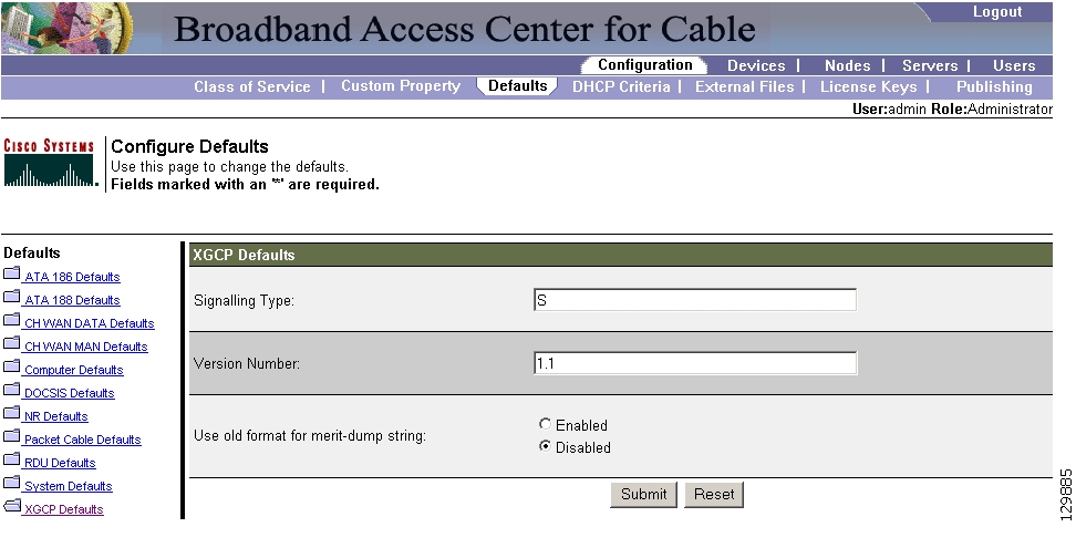
Gateway (xGCP) Control Protocol Defaults
XGCP is a gateway control protocol that lets external call agents control gateways in a Voice over IP (VoIP) environment. The Configure XGCP Defaults page ( Figure 10-11) displays a list of default values currently applied to the xGCP gateway devices supported by BACC.
Figure 10-11 Configure XGCP Page
Table 10-10 describes all fields and buttons appearing in Figure 10-11.
Note
Configuring DHCP Criteria
In BACC, DHCP criteria describe the specific criteria for a device when selecting a scope in Network Registrar. For example, a DHCP criteria called provisioned-docsis has an inclusion selection tag called tagProvisioned. The DHCP criteria is associated with a DOCSIS modem. When this modem requests an IP address from the Network Registrar, Network Registrar looks for scopes associated with the scope selection tag tagProvisioned.
To access the DHCP Criteria page:
Step 1
Step 2
Adding DHCP Criteria
To add a DHCP criteria:
Step 1
Step 2
Step 3
Step 4
Note
Step 5
Step 6
Step 7
Modifying DHCP Criteria
To modify existing DHCP criteria:
Step 1
Step 2
Step 3
Note
Deleting DHCP Criteria
Deleting DHCP criteria using the administrator application does not delete the actual DHCP server configurations from the DHCP server. You must delete the DHCP server configurations manually. To delete an existing criteria:
Step 1
Step 2
Step 3
Step 4
Note
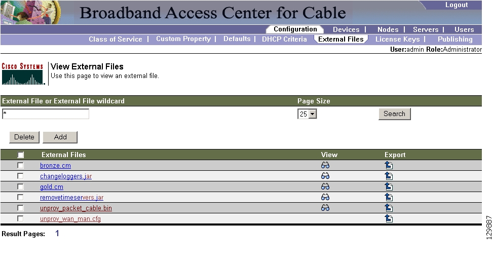
Managing External Files
Using the BACC administrative user interface, you can manage the TFTP server files or template files for dynamic generation for DOCSIS, PacketCable MTAs, and WAN-Man files, or software images for devices (see Figure 10-12). You can add, delete, replace, or export any file type, including:
•
Note
•
•
Note
Figure 10-12 Manage External Files Page
Table 10-11 identifies the fields and buttons shown in Figure 10-12.
Adding External Files
To add an existing external file:
Step 1
Step 2
Step 3
Step 4
Note
Step 5
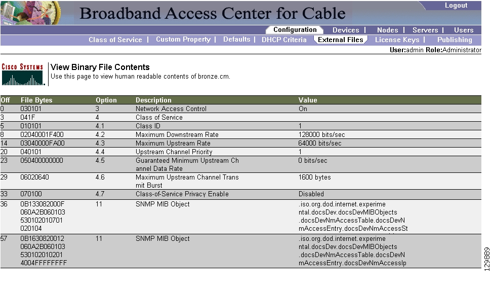
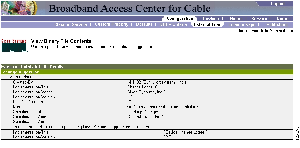
Viewing External Files
To view the contents of a DOCSIS or PacketCable voice technology external file:
Step 1
Step 2
Step 3
Step 4
Figure 10-13 Example Binary File Content
Figure 10-14 Example Jar File Content
Replacing External Files
To replace an existing external file:
Step 1
Step 2
Step 3
Step 4
Note
Step 5
Step 6
Note
Exporting External Files
You can copy external files to your local hard drive using the export function.
Note
To export a file:
Step 1
Step 2
Step 3
Step 4
Step 5
Deleting External Files
Complete this procedure to delete an existing external file:
Step 1
Step 2
Step 3
Step 4
Step 5
Step 6
Caution
Note
Managing License Keys
Software licenses are used to activate specific features or to increase the functionality of your installation. Each license is available as either a permanent license or an evaluation license.
•
•
Caution
When you upgrade from an evaluation license to a permanent license, you do not have to re-install the software. You can perform the upgrade directly from the BACC administrator user interface; you do not have to repeat the entire installation process.
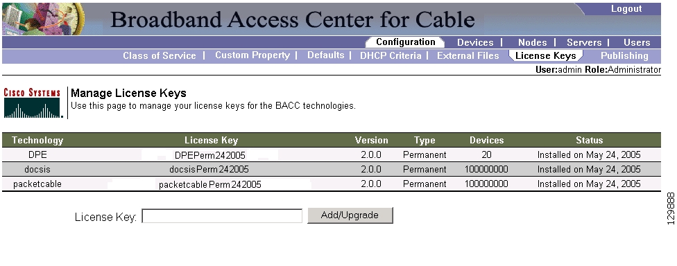
The Manage License Keys page ( Figure 10-15) displays a list of licenses that have been entered for your implementation. This BACC release supports both evaluation and permanent licenses for high-speed data (DOCSIS cable modems), PacketCable MTAs, ATAs, DPEs, CableHome WAN-Man and WAN-Data devices, and computers. The status of each available license is displayed as active, expired, not installed, or identifies the expiration date.
Note
Figure 10-15 Manage License Keys Page
Adding and Modifying a License
To add, modify, or upgrade a license:
Step 1
Step 2
Step 3
Step 4
Step 5
Managing Regional Distribution Unit Extensions
Creating a custom extension point is essentially a programming activity that can, when used in conjunction with the BACC administrator' s user interface, allow you to expand the quantity of device types and technologies supported.
Managing extensions includes:
•
Note
Writing a New Class
This procedure is included to better illustrate the entire custom extension creation process. You can create many different types of extensions; for the purposes of this procedure the a new Publishing Extension Point is used.
To write the new class:
Step 1
Step 2
Step 3
Installing RDU Custom Extension Points
After a Jar file is created, use the administrator's user interface to install it:
Step 1
Note
Step 2
Note
Step 3
Step 4
Step 5
Step 6
Viewing RDU Extensions
You can view the attributes of all RDU extensions directly from the View Regional Distribution Unit Details page. This page displays details on the installed extension Jar files and the loaded extension class files. See Viewing Regional Distribution Unit Details, page 9-24.
Publishing Provisioning Data
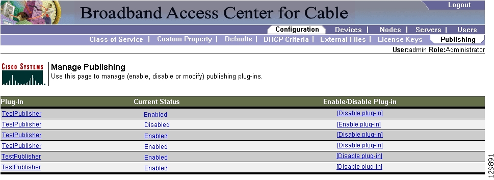
BACC has the capability to publish the provisioning data it tracks to an external datastore in real time. To do this, a publishing plug-in must be developed to write the data to the desired datastore. The Manage Publishing page, shown in Figure 10-16, identifies information such as the plug-in name, its current status (whether it is enabled or disabled), and switch to enable or disable it.
You can enable as many plug-ins as required by your implementation but care must be exercised because the use of publishing plug-ins can decrease system performance.
Note
Figure 10-16 Manage Publishing Page
Publishing Datastore Changes
To publish changes to an external datastore:
Step 1
Step 2
Step 3
Modifying Publishing Plug-In Settings
These settings are a convenient way for plug-in writers to store plug-in settings in the RDU for their respective datastore. To modify the publishing plug-in settings:
Step 1
Step 2
Step 3
Table 10-12 identifies the fields shown in the Modify Publishing Plug-Ins page.
Step 4
Step 5
Configuring the SRV Record in the Network Registrar DNS Server
You must configure the Network Registrar DNS server to operate with the KDC. Refer to your Network Registrar documentation, and these instructions, to perform this configuration.
Note
Step 1
Step 2
nrcmd> zone voice.acme.com create primary <address of nameserver> hostmasterStep 3
nrcmd> zone voice.acme.com. addRR _kerberos._udp. srv 0 0 88 <address of KDC>Step 4
nrcmd> savenrcmd> dns reload
Configuring SNMPV3 Cloning on the RDU and DPE for Secure Communication with PacketCable MTAs
BACC lets you enable an external network manager for SNMPV3 access to MTA devices. Additionally, the RDU is capable of performing SNMPV3 operations in a specific MTA.
To enable this capability, set the security key material at the DPEs and RDU. After the key material has been set, the BACC API calls that are used to create cloned SNMPV3 entries are enabled.
Note
Creating the Key Material and Generating the Key
Creating the key material is a two-step process. First, run a script command on the RDU and then run a CLI command on the DPE.
Note
To create the key material:
Step 1
generateSharedSecret.sh <password>Where the <password> is any password, 6 to 20 characters in length, that you create. This password is then used to generate a 46 byte key. This key is stored in a file, called keymaterial.txt, that is located in the <BACC_HOME>/rdu/conf directory.
Step 2
This generates the same 46 byte key on the DPE and ensures that the RDU and DPE(s) are synchronized and can communicate with the MTA securely.
Automatic FQDN Generation
When configuring the PacketCable voice technology, a fully qualified domain name (FQDN) must reside in the BACC database for each voice device, whenever the KDC queries the registration server for that FQDN. The BACC automatic FQDN generation feature is not limited to use by any single voice technology; it can be used by any BACC technology.
Automatically Generated FQDN Format
An automatically generated FQDN in BACC follows this format:
prefix<htype>-<hlen>-aa-bb-cc-dd-ee-ffsuffix.domainWhere:
•
Note
•
The entry of a prefix and suffix property is optional. If you do not specify these properties, and a host name is not specified during PacketCable MTA provisioning and, if neither the prefix nor suffix property is defined in the BACC property hierarchy, the device's MAC address followed by the domain name are used as the generated FQDN.
For example:
A device with the MAC address 1,6,aa:bb:cc:dd:ee:ff will have this FQDN generated:
aa-bb-cc-dd-ee-ff.domainSpecifically, when configuring for PacketCable and many other technologies, the domain name property must also be configured. If you do not specify a domain name while provisioning a PacketCable MTA, the BACC property hierarchy is searched and, if it is not found, the MTA is not provisioned. However, if you do specify the domain name during MTA provisioning, that domain name will be used regardless of the domain name property that is specified in the BACC property hierarchy.
Properties for Automatically Generated FQDNs
Properties can be defined at any acceptable point in the BACC property hierarchy. You can use the System Defaults, Technology Defaults, DHCP Criteria, or Class of Service to accomplish this, and you can also do this at the device level.
FQDN Validation
There are a few things to consider when entering the information that is used to generate an FQDN. These include:
•
•
•
Note
Sample Automatic FQDN Generation
This section provides an example of creating an automatically generated FQDN.
Step 1
Note
Step 2
In this example, a device with MAC address 1,6,aa:bb:cc:dd:ee:ff will yield an automatically generated FQDN of 1-6-aa-bb-cc-dd-ee-ff.pctest.com. Additionally, the Automatic FQDN Generation field should be enabled in the device's default configuration.
![]()
![]()
![]()
![]()
![]()
![]()
![]()
![]()
Posted: Thu Feb 2 13:09:52 PST 2006
All contents are Copyright © 1992--2006 Cisco Systems, Inc. All rights reserved.
Important Notices and Privacy Statement.