|
|

The BAC software provides network and service management tools that enable the provisioning of devices and subscribers in broadband aggregation environments.
BAC supports the role of the following devices as broadband aggregators:
Table 3-1 Provisioning Flows Topics
| If you want to... | Go to the... |
|---|---|
Review an example use of BAC in a PTA over Ethernet over ATM environment |
"Provisioning in a PTA over Ethernet over ATM Environment" section. |
Review an example use of BAC in offering subscribers differentiated classes of services |
Table 3-1 lists the topics discussed in this chapter.
BAC supports the ability of access routers to aggregate the broadband facilities of network access providers and enables network service providers to provide Internet access to subscribers through these broadband facilities. BAC provides device management for these routers and supports their use in the following scenarios:
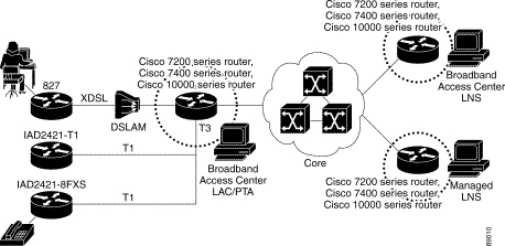
Figure 3-1 illustrates the role of BAC in a LAC/LNS architecture or a PTA architecture. The router at the center of the figure can act as both a LAC and a PTA depending on how you configure its interfaces. In a LAC/LNS scenario, an ATM permanent virtual connection (PVC) or an Ethernet packet passes through the LAC and terminates at an LNS. In the PTA scenario, the PVC or an Ethernet packet terminates at the PTA and traffic is routed onto a LAN.
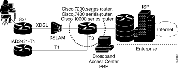
Figure 3-2 illustrates the role of BAC in an RBE scenario. In this scenario, no authentication occurs and traffic is routed directly to the Internet.
In a broadband aggregation environment, a complete provisioning flow consists of the following high-level steps:
2. Network and device configuration
3. Subscriber and service provisioning
To help you understand how and where to use the BAC application, the sections that follow present a series of example use cases.
A retail service provider, called ISP1, wants to begin using BAC to configure Cisco routers as PTAs and to provision subscribers with PTAPPPoEoA service. The network configuration requirements are as follows:
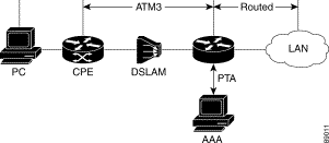
Figure 3-3 illustrates the network configuration.
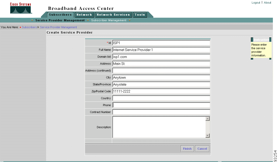
1. A BAC administrator creates ISP1, assigning to this service provider an identifier, as shown in Figure 3-4.
The identifier ensures that the BAC software partitions the network properly so that only ISP1 administrators and operators can view network device and subscriber information.
Creating the service provider also automatically creates ISP1 on the Security Policy Engine (SPE) server, the BAC user management tool. You can later use this tool to create operators for ISP1 with differing levels of authority.
2. The BAC administrator adds network services. Network services are resources that support device and subscriber provisioning. For example, in a PTAPPPoEoA environment, an administrator might add a AAA server, an access list, a class map, and a policy map. For more detailed information about this process, see "Enabling Differentiated Classes of Service" section.
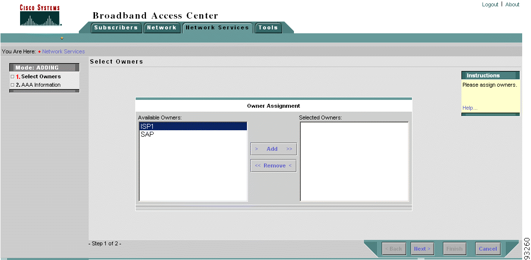
a. For each of these services, the administrator selects an owner. Figure 3-5 illustrates selecting an owner of the AAA server.
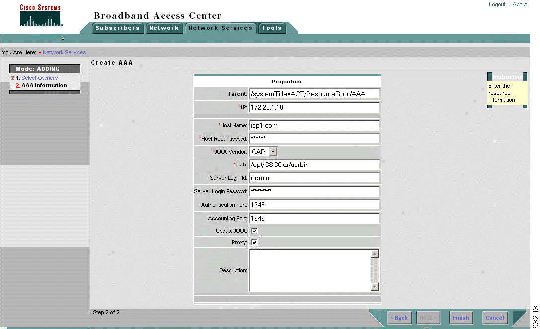
b. The administrator then defines the properties of the resource. Figure 3-6 illustrates defining the properties of AAA server. For more information, see "Managing Network Services."
3. The BAC administrator creates a logical grouping called an administrative network. To create an administrative network, the administrator does the following:
a. Provides identifying information; that is, the name of the network and the domain to which it belongs.
b. Assigns the owner of the network, using the method illustrated in Figure 3-5.
c. Adds AAA resources, selecting from among those AAA resources defined in the second task.
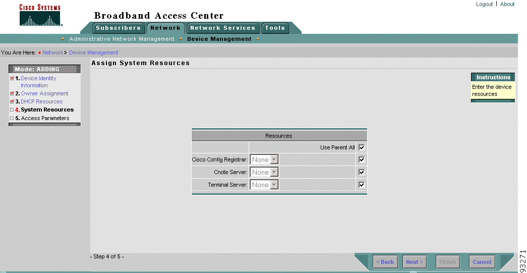
d. Adds system resources, as illustrated in Figure 3-7.
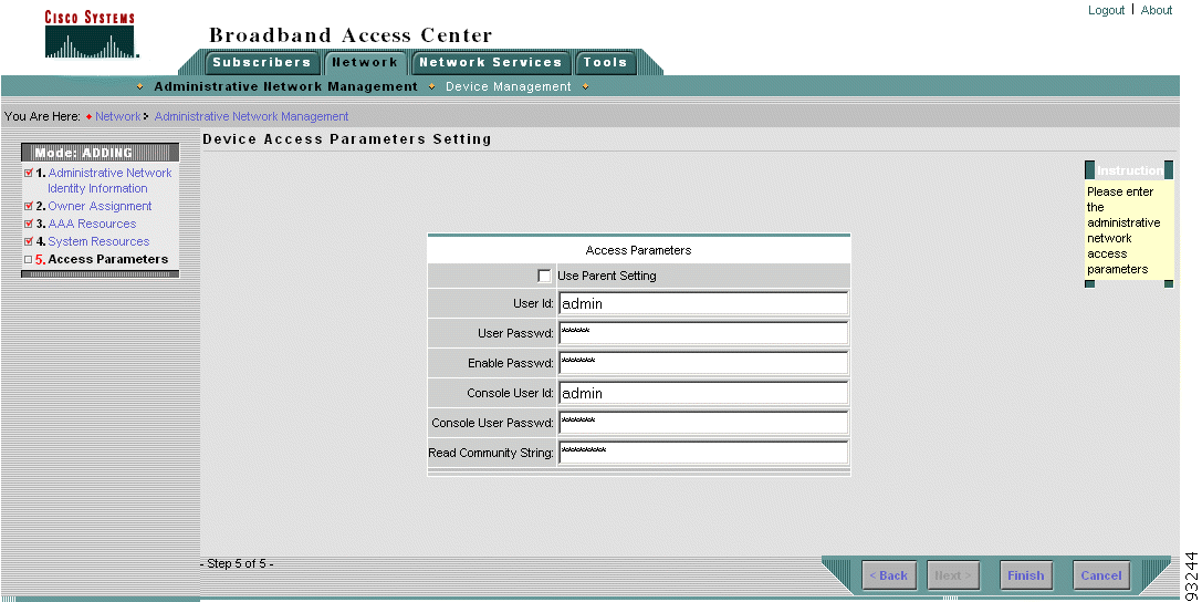
e. Defines access parameters for network devices, as illustrated in Figure 3-8.
For more information about administrative networks, see "Managing Devices."
4. The BAC administrator adds network devices and associates the devices with administrative networks and network resources. To add devices, the administrator does the following:
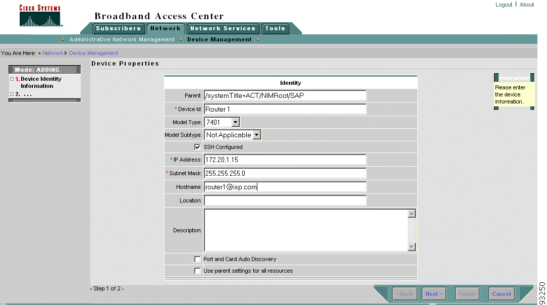
a. Defines device properties, as illustrated in Figure 3-9.
b. Assigns the owner of the device, using the method illustrated in Figure 3-5.
c. Adds AAA resources, selecting from among those AAA resources assigned to the administrative network.
d. Adds system resources, as illustrated in Figure 3-7. The administrator might choose to inherit the system resources set on the parent administrative network or choose to override the parent settings.
e. Sets the access parameters for this device, as illustrated in Figure 3-8. The administrator might choose to inherit the system resources set on the parent administrative network or choose to override the parent settings.
For more information about adding devices, see "Managing Devices."
5. The BAC administrator adds PTAPPPoEoA service to the device. To add this service, the administrator does the following:
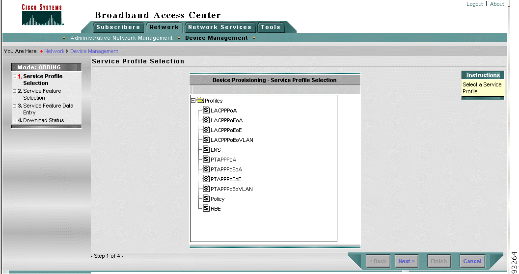
a. Selects the PTAPPPoEoA service profile, as illustrated in Figure 3-10.
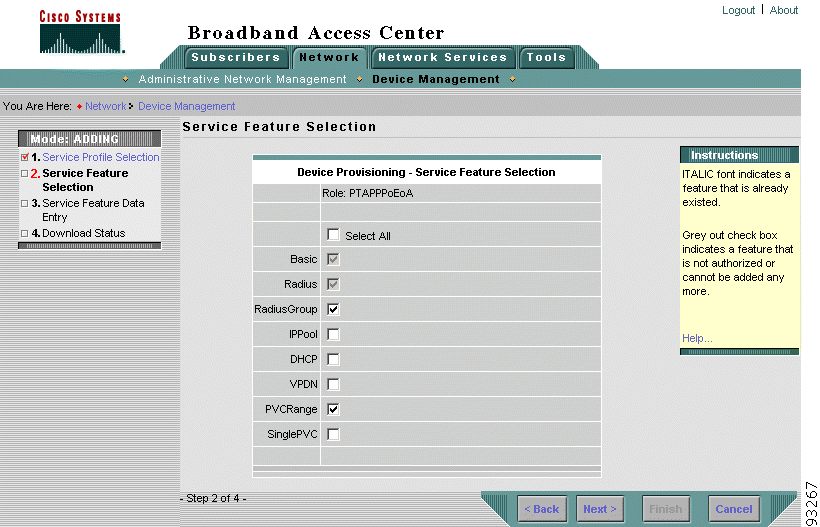
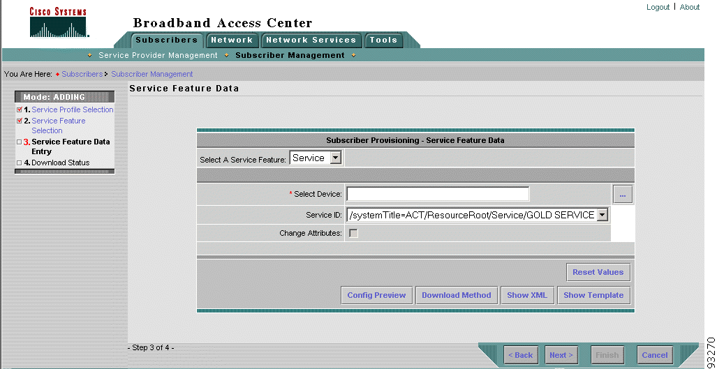
b. Selects service features to add to the device, as illustrated in Figure 3-11. The administrator must check Basic. All other service features depend on the Basic feature. In Figure 3-11, the administrator checks Basic, Radius, Radius Group, and PVC Range.
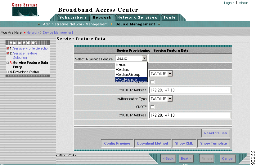
c. Selects service features to configure, as illustrated in Figure 3-12.
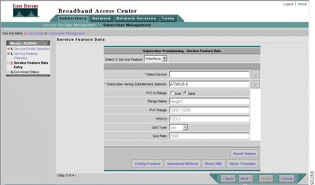
For example, for the PVC Range feature, the administrator defines:
The administrator also selects the subscriber-facing interface and a subinterface to which to apply the PVC range characteristics.
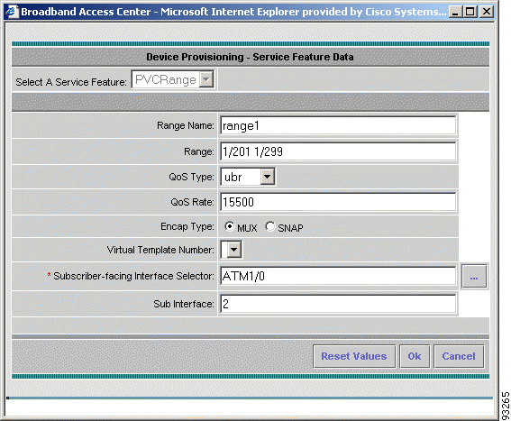
Figure 3-13 illustrates defining the PVC Range through the Device Provisioning - Service Feature Data dialog box.
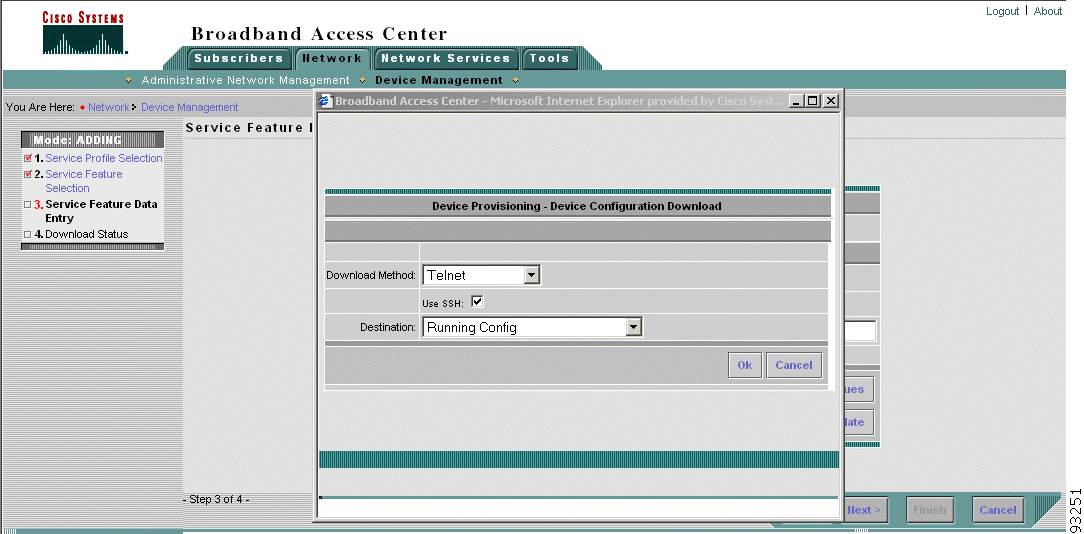
e. Chooses a method for downloading the configuration, as illustrated in Figure 3-14.
For more information, see "Provisioning Broadband Aggregators."
For more information about adding services to a device, see "Provisioning Broadband Aggregators."
6. The BAC administrator logs into the Cisco Security Policy Engine application to create an ISP1 operator account. For more information about adding operators and other users with authority to access BAC, see "Cisco Security Policy Engine Administration Server User Interface."
7. The newly created operator logs in.
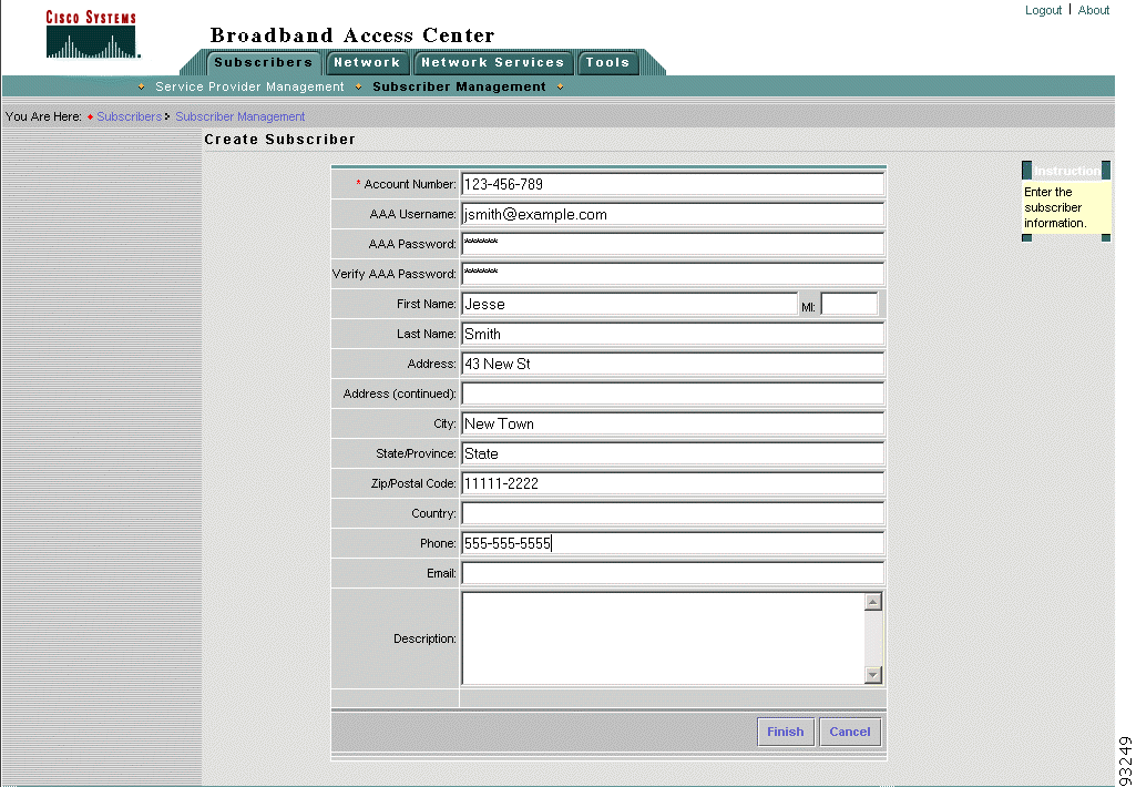
8. The operator creates a subscriber account by providing an account number, AAA server information, and other basic account data, as illustrated in Figure 3-15.
9. The operator adds PTAPPPoEoA service to the subscriber. To add this service, the administrator does the following:
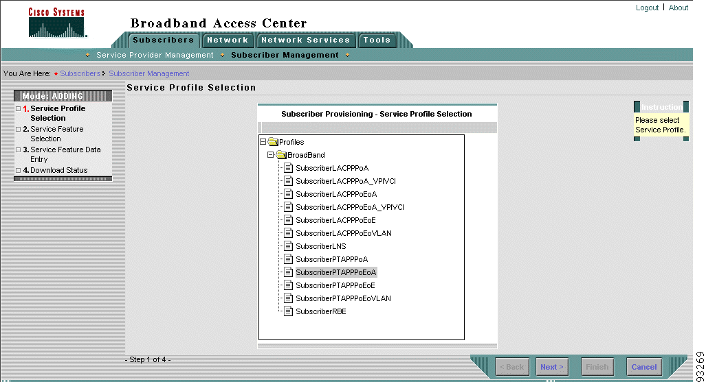
a. Selects the SubscriberPTAPPPoEoA profile, as illustrated in Figure 3-16.
b. Enters subscriber interface feature data, as illustrated in Figure 3-17.
c. Defines the subscriber's class of service, as illustrated in Figure 3-18.
For more information about adding subscribers and subscriber profiles, see "Managing Subscribers."
A retail service provider, called ISP1, currently offers its subscribers one basic class of service. Now, ISP1 wants to begin offering differentiated classes of service.
1. A technical operator with the appropriate BAC authorization logs in to the Web UI.
2. The operator clicks the Network Services tab and then goes to the QoS folder to create access lists, class maps, and policy maps.
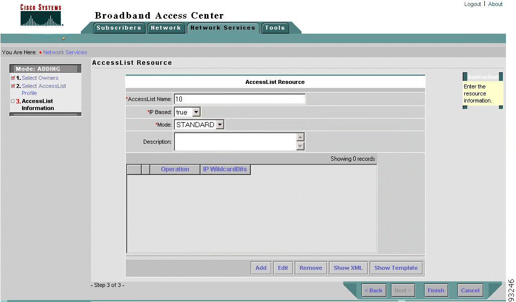
3. To create an access list, the operator does the following:
a. Selects the access list owner.
b. Selects the access list configuration profile.
c. Provides the basic access list information, as illustrated in Figure 3-19.
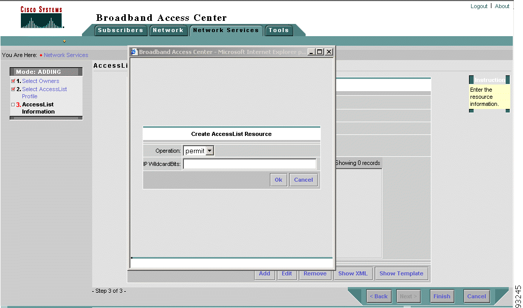
d. Sets the permit/deny operation and wildcard bits information using the Create Access List Dialog Box, as illustrated in Figure 3-20.
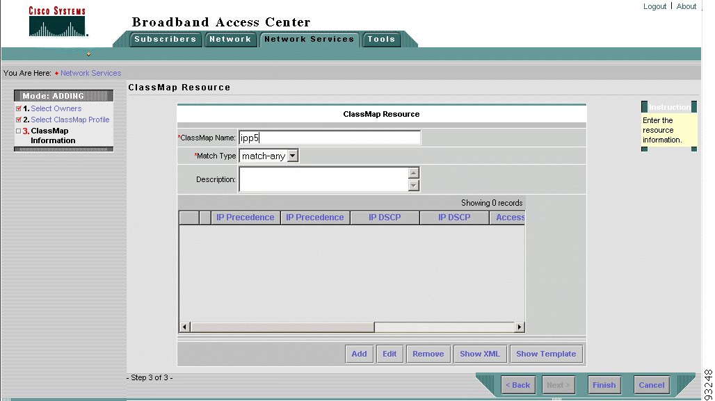
4. To enable routers to handle network traffic based on classification, the operator creates a class map. The operator does the following:
a. Selects the class map owner.
b. Selects the class map configuration profile.
c. Provides the basic class map information, as illustrated in Figure 3-21.
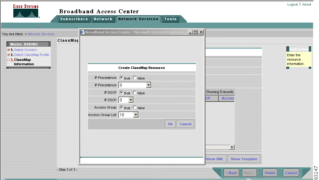
d. Provides class map details such as IP precedence values and IP differentiated services code point (DSCP) values using the Create Class Map Resource dialog box, as illustrated in Figure 3-22.
5. To create a policy map that defines Quality of Service (QoS) actions and rules and to associate these with the class map, the operator does the following:
a. Selects the policy map owner.
b. Selects the policy action configuration profile.
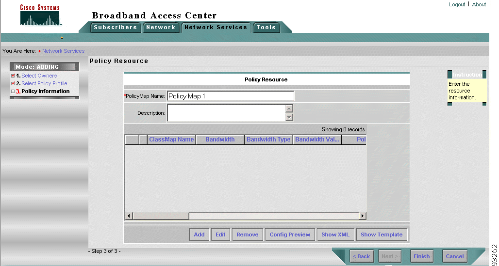
c. Provides the basic policy map information, as illustrated in Figure 3-23.
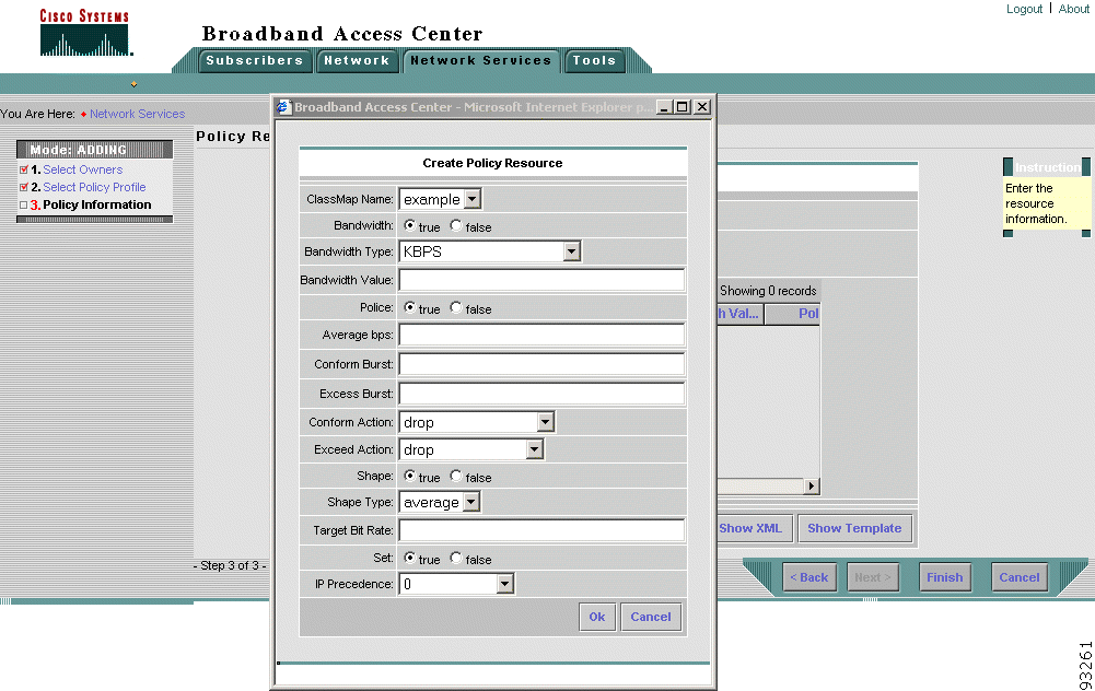
d. Associates the policy with a class map and provides bandwidth, traffic policing, and traffic shaping information using the Create Policy Resource dialog box, as illustrated in Figure 3-24.
6. The operator creates Gold service. To create Gold service, the operator does the following:
b. Selects the service configuration profile.
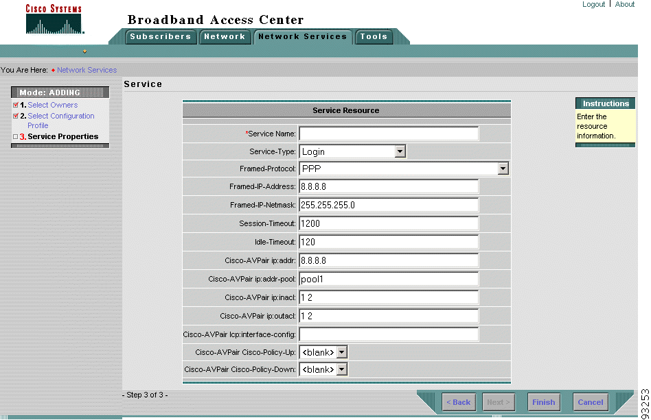
c. Provides the service information, including the policies to apply to inbound and outbound interfaces, as illustrated in Figure 3-25.
 |
Note If you are applying the policy to the interfaces of Cisco 7200 series routers and Cisco 7400 series routers, make sure you set the Cisco-AVPair Cisco-Policy-Up and Cisco-AVPair Cisco-Policy-Down fields to None. |
7. Repeats the process as necessary to provide Silver and Bronze service.
![]()
![]()
![]()
![]()
![]()
![]()
![]()
![]()
Posted: Wed May 21 08:49:30 PDT 2003
All contents are Copyright © 1992--2003 Cisco Systems, Inc. All rights reserved.
Important Notices and Privacy Statement.