|
|

Table Of Contents
Configuring Service Ports on the DPE
Provisioning Group Scalability and Failover
Adding DPE to a Provisioning Group
Configuring CWMP Service
This chapter describes how to configure the CWMP service in Broadband Access Center (BAC). Topics covered are:
–
Configuring Service Ports on the DPE
–
•
–
Note
CWMP Service Configuration
CWMP is a specification of a set of remote procedure calls (RPCs), for example, GetParameterValues, SetParameterValues, and so on. These RPCs define the generic mechanism by which BAC reads or writes parameters to customer premises equipment (CPE) in order to manage it. These parameters include:
•
•
•
You can enable or disable CWMP features on the DPE by using the DPE CLI.
Among the features that you can configure on the DPE are:
•
•
•
•
•
•
•
•
For information on how to configure these properties, refer to the Cisco Broadband Access Center DPE CLI Reference, Release 3.0.
Configuring Service Ports on the DPE
You can configure the ports on which the CWMP services communicate with a device. You can independently configure each instance of the CWMP services—the CWMP RPC service and the HTTP file service—to suit your requirements. Table 12-1 describes how you configure ports for each service.
Connection Request Service
Connection requests instruct the device to establish a CWMP session with the DPE. You can use the BAC connection request service to activate a configuration on a device, execute firmware changes to the device, or execute immediate operations upon the device.
Initiated by the DPE, connection requests are the only method available to the DPE to establish a session with a device. Once a session is established, the device or the DPE may perform any RPCs, including device operations and configuration changes.
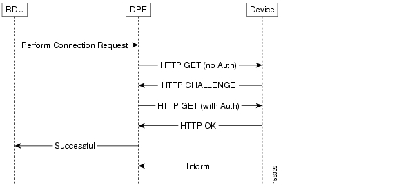
Figure 12-1 Connection Request in BAC
Figure 12-1 describes the flow of a connection request in BAC. The RDU delegates the connection request to the best available DPE in the device's provisioning group. Once the connection request ends, the DPE notifies the RDU of the result.
Configuring Connection Request Options
You can use BAC to control the behavior of connection requests by configuring your preferences for:
•
Note
Configuring Authentication
Two properties that you set on the device object in the RDU affect authentication. They are:
•
–
IPDeviceKeys.CONNECTION_REQUEST_USERNAME–
IPDeviceKeys.CONNECTION_REQUEST_PASSWORD•
–
–
You can also set the connection request username and password while adding a device on the Add Device page, and change the username and password in the Modify Device page.
Both properties control the connection request username and password that are used in DPE-CPE authentication. This username and password differ from the username and password used to authenticate CWMP sessions between the DPE and a device. These properties are for a single device; thus, they can be set only on the device object.
If you have not specified a connection request password, the CWMP session password that authenticates a device to the DPE is used. If the connection request username is also not specified, the device ID is used.
Note
Note
Configuring Connection Request Methods
You can specify the method in which BAC attempts to perform a connection request by using the provisioning API or the administrator user interface. The selected method dictates how BAC determines the connection request URL to be used to contact the device.
The API property
IPDeviceKeys.CONNECTION_REQUEST_METHODspecifies the connection request method (subsequent descriptions provide the details of each method).
Note
To configure the default connection request method by using the administrator user interface, choose Configuration > Default > CWMP Defaults, and select an option from the drop-down list.
BAC supports three methods to configure a connection request:
•
•
•
When selecting a connection request method, it is important to consider performance and manageability, as each method provides different levels of both. Refer to the recommendation for each method before choosing your method of connection requests.
Discovered Connection Request
The Discovered method, during CPE interactions with the DPE, modifies the data synchronization instruction to discover the device's connection request URL, which corresponds to the parameter InternetGatewayDevice.ManagementServer.ConnectionRequestURL, whenever the DPE interacts with the device. The RDU records any updates to this parameter value and uses it when making connection requests.
Note
Recommendation: Because this parameter value changes each time the device's WAN IP address changes and every update has to be stored at the RDU, it is not the optimal method for
connection requests.Use FQDN Connection Request
The Use FQDN method uses the fully qualified domain name (FQDN) specified for the device at the RDU to construct a connection request URL for the device. It uses the FQDN along with the values specified in the following properties on the API:
•
IPDeviceKeys.CONNECTION_REQUEST_PORT•
IPDeviceKeys.CONNECTION_REQUEST_PATHYou can also specify these properties on the administrator user interface:
Step 1
Step 2
•
•
Step 3
Note
IPDeviceKeys.CONNECTION_REQUEST_PORTandIPDeviceKeys.CONNECTION_REQUEST_PATH, respectively.Step 4
Note
Recommendation: Because the Use FQDN method relies on the DNS being updated with the device's correct IP address, you do not need to update BAC whenever the device IP address changes. Subsequently, this option is the most scalable one for connection requests.
Use IP Connection Request
The Use IP method discovers the device's WAN IP address by using the same mechanism as the Discovered method. Then, it constructs a connection request URL for the device by using the values in the following API properties:
•
IPDeviceKeys.CONNECTION_REQUEST_PORT•
IPDeviceKeys.CONNECTION_REQUEST_PATHYou can also specify these properties on the administrator user interface:
Step 1
Step 2
•
•
Step 3
Note
IPDeviceKeys.CONNECTION_REQUEST_PORTandIPDeviceKeys.CONNECTION_REQUEST_PATH, respectively.Step 4
Recommendation: Because the Use IP method relies on the RDU having the device's WAN IP address, it requires the WAN IP address to be discovered before connection requests are attempted. And because the device's WAN IP address changes, the RDU must be updated with the new IP address. Subsequently, this option is not the optimal method for connection requests.
Disabling Connection Requests
You can choose to disable the connection request service. This option is useful if a device uses NAT and connection requests are not possible.
Note
Configuring Reachability
Reachability plays an important role in configuring connection requests. BAC refuses connection requests if a device's reported IP address and its source IP address do not match because this implies that the device uses the NAT standard, and therefore, configuration requests would not normally succeed. You can change this behavior from the administrator user interface or the API.
By using the API, set the property
IPDeviceKeys.FORCE_ROUTABLE_IP_ADDRESSto true to allow connection requests regardless of a mismatch in the device source IP address.From the administrator user interface:
Step 1
Step 2
•
•
Step 3
Note
IPDeviceKeys.FORCE_ROUTABLE_IP_ADDRESS.Step 4
Note
Discovering Data from Devices
This section describes the Discovery of Data feature, which you use to retrieve a predefined set of parameters from the device, and store these parameters in the RDU for future use. You can use this discovered data to manage device firmware and device configurations by providing some key attributes of the device and its current configuration. Discovered parameters are updated at the RDU any time their values change on the device.
You can configure data discovery at the RDU. The RDU forwards discovery policy instructions and the values of parameters, discovered for each device during the previous discovery process, to the appropriate DPEs. During interactions with the device, the DPE consults the discovery policy instructions specific to the device to determine what parameters need to be discovered.
Once parameter values are discovered, existing device parameters are compared with those already stored for the device. If the values have changed or are being obtained for the first time, this data is updated at the RDU. If the RDU is not available to receive the update, the newly discovered data is dropped, and the entire process of data discovery is initiated the next time the device connects with the DPE.
Discovered parameters are stored on device records and you can view them by using the administrator user interface or obtain them via the API
IPDevice.getDetails()call. To view discovered parameters via the user interface, access the Manage Devices page under the Devices tab on the primary navigation bar. Locate the device by using the search options, and click the View Details icon () corresponding to the device. The Device Details page appears, displaying details of the discovered parameters for the device.
The following sections describe:
•
Configuring Data Discovery
Data discovery policy is configured via the RDU and includes parameters checked:
•
•
While the discovery of data process executes every time a device establishes contact with the DPE, you can configure validation of certain parameters to occur only if the device has reported a new firmware version. This check eliminates the need to validate parameters whose values change only with a firmware upgrade. For example, the device model name does not change without a firmware upgrade; thus, you do not need to check this parameter on the device unless the firmware has been upgraded.
BAC ships with a default configuration for data discovery. You can augment this default configuration in two ways:
•
•
Configuring Parameters Checked on Every Contact
You can configure the default list of parameters discovered everytime the device connects with the DPE by using the
ServerDefaultsKeys.CWMP_DISCOVER_PARAMETERSproperty. You can add more parameters to the default list by providing a comma-separated list of parameters as a value to theIPDeviceKeys.CWMP_CUSTOM_DISCOVER_PARAMETERSproperty. The default list includes:•
•
•
•
•
•
For example:
IPDeviceKeys.CWMP_CUSTOM_DISCOVER_PARAMETERS= InternetGatewayDevice.ManagementServer.URL,
InternetGatewayDevice.ManagementServer.PeriodicInformEnable
Configuring Parameters Checked on Firmware Upgrade
You can configure the default list of parameters discovered after every firmware upgrade by using the
ServerDefaultsKeys.CWMP_FIRMWARE_CHANGED_CPE_PARAMETERSproperty. This default list includes the InternetGatewayDevice.DeviceInfo.ModelName parameter.To customize this list to include more parameters, use the
IPDeviceKeys.CWMP_CUSTOM_FIRMWARE_CHANGED_PARAMETERSproperty.Troubleshooting Data Discovery
You can also troubleshoot data discovery from the DPE CLI by using any of the tasks described in Table 12-2.
Provisioning Group Scalability and Failover
This section describes the scalability and failover features provided in this release of BAC.
BAC's scalability and failover provide a high degree of availability to suit networks of virtually any size, even those with millions of devices deployed. The product also provides such critical features as DPE redundancy and failover protection.
Scalability in a BAC deployment is accomplished through provisioning groups, each of which is a cluster of redundant DPE servers that communicate with a set of CPE. Provisioning groups enhance the scalability of the BAC network by making each provisioning group responsible only for a subset of devices. This partitioning of devices can be along regional groupings or any other policy defined by the service provider.
To scale a deployment, the administrator can:
•
•
•
BAC supports explicit assignment and automatic membership of devices to provisioning groups. For more information, see CPE Management Overview.
Redundancy in BAC
Redundancy helps to ensure:
•
•
BAC supports local as well as regional server redundancy.
Local Redundancy
The BAC provisioning group is a cluster of redundant DPE servers that communicate with a set of CPE. A single URL identifies each provisioning group. All CPE requests to a provisioning group are load-balanced between available DPEs, with each DPE capable of processing any device in its provisioning group.
Regional Redundancy
Regional redundancy ensures that DPEs in a different location temporarily process CPE requests in case of regional failure. The simplest way of facilitating this deployment is to set up DPEs within a provisioning group in different geographic locations. In such a setup, CPE requests are serviced by DPEs located in different regions, providing regional failover within the confines of the provisioning group.
In some deployments, however, you may require that CPE requests be processed by servers in one location and fail over to DPEs in another location only in case of failure. In such a scenario, you can also locate DPEs for a provisioning group in different regions yet configure the network such that, under normal conditions, CPE requests are directed only to a subset of the DPEs in a particular region.
Typically, you can configure regional redundancy by using DNS techniques. To configure the network for regional redundancy, ensure that the BAC hostname of a given provisioning name normally resolves to IP address(es) representing one set of DPEs. But when none of the DPE servers in that set responds to keepalives, such as ICMP, HTTP GET, or a TCP handshake), the DNS server should resolve the BAC hostname to the IP address(es) of the DPEs from a second set. CPE requests are then directed to a different set of DPEs. Since DPEs in both sets belong to the same provisioning group, the new DPEs are ready to respond to requests. Subsequent DNS lookup requests fall back to the primary set of DPEs as soon as they become available.
You can configure regional redundancy by using any software or hardware that provide load-balancing features, such as the Cisco 11500 Content Services Switch.
DPE Load-Balancing
BAC supports the following mechanisms for DPE redundancy and load-balancing:
•
Using DNS Round Robin
In using the DNS round-robin mechanism, the DNS server shuffles the list of DPE IPs when resolving the autoconfiguration server (ACS) hostname for the device. The device then takes the first IP address in the list as the ACS hostname.
This option is not recommended if the service provider does not control DNS caching servers. Also, DNS round-robinning performs less than ideally in a power outage scenario, when a large number of devices may receive the same order IP address cached by the DNS server, thus impacting performance. To work around this issue, Cisco recommends configuring a very short TTL of 1 second on the DNS server.
Using a Hardware Load Balancer
In using a hardware load balancer, the ACS URL contains the IP address or is resolved by the DNS server to a single IP address. All DPEs for a provisioning group are hidden behind a single virtual IP address of the hardware load balancer, such as the Cisco 11500 Content Services Switch (CSS). You configure the hardware load balancer to translate its virtual IP address to a specific DPE IP address based on any number of load-balancing algorithms. A redundant pair of load balancers can improve redundancy and may service more than one provisioning group.
Adding DPE to a Provisioning Group
This section describes how to add a DPE to a new provisioning group. In adding a DPE to a provisioning group, there are three possible options:
•
•
•
To add a DPE to a provisioning group:
Step 1
•
dpe# dpe provisioning-group primary name–
•
dpe# dpe rdu-server {host | ip} port–
–
–
•
dpe# interface ethernet {intf0 | intf1} provisioning fqdn fqdn–
–
You must use the same FQDN for all DPEs in a given provisioning group. If DPEs are located behind the load balancer, use the FQDN of the load balancer as the interface FQDN, and ensure that it is the same for all DPEs which are part of the same load-balancing group.
Note
Step 2
Step 3
Step 4
DPE Load-Balancing by Using Cisco CSS
This section describes how to configure Cisco 11501 CSS for load-balancing BAC traffic. The Cisco CSS front-end server handles the incoming TCP traffic from the CWMP devices that BAC supports and load-balances the TCP sessions across the Cisco CSS back-end servers, in this case, the DPEs.
Note
Initial CSS Configuration
When you first power up a Cisco CSS, a startup configuration menu appears, in which you set a minimum configuration, which includes the IP address, subnet mask and default gateway for the Ethernet management port. Do not configure this information.
Then, you are prompted to change the default username (admin) and password (system). Optionally, you can change these credentials. The username should be between 1 and 16 characters long and the password should be between 6 and 16 characters.
You are then prompted for additional configuration information, which you must provide if the running-configuration and the startup-configuration are cleared later.
Example 12-1 shows a Cisco CSS initial configuration:
Example 12-1 Cisco CSS Initial Configuration
Checking for Existing Config...No startup-config was found, continue with the setup script [y/n]? yNote: Pressing 'q' after any prompt quits setup.Pressing <CR> after any [y/n] defaults to 'y'.Warning: All circuit VLAN IP addresses must be on a differentsubnet than the Ethernet Mgt port IP address.The existing Ethernet Mgt port IP address is: 0.0.0.0Add an IP address to VLAN1: [default = 192.168.10.1]? 10.86.147.51Add an IP subnet mask to VLAN1: [default = 255.255.255.0]? 255.255.255.224Would you like to specify a default gateway? [y/n]? yWarning: The default gateway IP address must be on the same subnetas VLAN1. VLAN1 IP address is: 10.86.147.51Add IP address for default gateway: [default = 10.86.147.2]? 10.86.147.33Pinging the default gateway: 0% Success.Which feature do you want to configure?[1] Layer3 load balancing[2] Layer5 load balancing[3] Proxy cache[4] Transparent cache[5] Exit scriptEnter the number of the feature you want to configure: 5Showing the Running ConfigCSS11501# show running-config!Generated on 07/17/2006 13:00:30!Active version: sg0750103configure!*************************** GLOBAL ***************************ip route 0.0.0.0 0.0.0.0 10.86.147.33 1!************************** CIRCUIT **************************circuit VLAN1ip address 10.86.147.51 255.255.255.224CSS11501#Since VLAN 1 is the default VLAN, all eight ports on Cisco CSS can be used as the front-end port for Cisco CSS. But for the purpose of this example, Ethernet port 0 is used as the front-end server port. The front-end router or switch is used to allow access to Cisco CSS or the DPEs from the customer network, and the IP address of the interface on this switch or router connected to Cisco CSS is the address configured on Cisco CSS for the default gateway (10.86.147.33). The FTP server (IP address 10.86.147.53) is connected to Ethernet port 8 on Cisco CSS. This FTP server is used in a later configuration.
Configuring DPE Load-balancing on Cisco CSS
You can use the configuration described in this section to perform simple load-balancing of the traffic from devices in the customer network between the back-end DPE servers. The load-balancing algorithm used is a simple round-robin. The CWMP devices use HTTP to connect to Cisco CSS, and the connections are passed through as HTTP to the DPE servers.
Note
Example 12-2 Configuring DPE Load-Balancing on Cisco CSS
The following example describes a configuration with two DPE servers on the same subnet. The DPE servers in this example have IP addresses of 11.32.0.26/12 and 11.32.0.27/12. The IP address of the back-end server Cisco CSS VLAN assigned to the Ethernet ports is 11.32.0.1/12. The VIP address and TCP port that are configured in the content rule are 10.86.147.52 and 7547. The CWMP devices use a URL to connect to Cisco CSS to load-balance between the DPEs; the URL is http://10.86.147.52:7547/acs.
Step 1
CSS11501#config t<cr>Step 2
CSS11501(config)#interface e1<cr>CSS11501(config-if[e1])#bridge vlan 2<cr>CSS11501(config-if[e1])#interface e2<cr>CSS11501(config-if[e2])#bridge vlan 2<cr>CSS11501(config-if[e2]}#exit<cr>Step 3
CSS11501(config)#circuit VLAN2<cr>CSS11501(config-circuit[VLAN2])#ip address 11.32.0.1/12<cr>Create ip interface <11.32.0.1>, [y/n]:y<cr>CSS11501(config-circuit-ip[VLAN2-11.32.0.1])#exit<cr>CSS11501(config-circuit[VLAN2])#exit<cr>Step 4
Note
CSS11501(config)# service DPE-1<cr>Create service <DPE-1>, [y/n]:yCSS11501(config-service[DPE-1])#keepalive type tcp<cr>CSS11501(config-service[DPE-1])#keepalive port tcp 7547<cr>CSS11501(config-service[DPE-1])#ip address 11.32.0.26<cr>CSS11501(config-service[DPE-1])#active<cr>CSS11501(config-service[DPE-1])# service DPE-2<cr>Create service <DPE-2>, [y/n]:yCSS11501(config-service[DPE-2])# keepalive type tcp<cr>CSS11501(config-service[DPE-2])# keepalive port 7547<cr>CSS11501(config-service[DPE-2])# ip address 11.32.0.27<cr>CSS11501(config-service[DPE-2])# active<cr>CSS11501(config-service[DPE-2])#exit<cr>Step 5
CSS11501(config)# owner User1<cr>Create owner <User1>, [y/n]:yCSS11501(config-owner[User1])#Step 6
Note
CSS11501(config-owner[User1])# content Clear-text<cr>Create content <Clear-text>, [y/n]:yCSS11501(config-owner-content[User1-Clear-text])# protocol tcp<cr>CSS11501(config-owner-content[User1-Clear-text])# port 7547<cr>CSS11501(config-owner-content[User1-Clear-text])# add service DPE-1<cr>CSS11501(config-owner-content[User1-Clear-text])# add service DPE-2<cr>CSS11501(config-owner-content[User1-Clear-text])# vip address 10.86.147.52<cr>CSS11501(config-owner-content[User1-Clear-text])#active<cr>CSS11501(config-owner-content[User1-Clear-text])#exit<cr>CSS11501(config-owner[User1])#exit<cr>CSS11501(config)#exit<cr>CSS11501#Step 7
CSS11501# copy running-config startup-config<cr>Working..(\) 100%CSS11501#Configuring Client Certificate Authentication on Cisco CSS
In the following example, the device uses SSL to connect to Cisco CSS. The connections are passed through as HTTP to the DPE servers. Cisco CSS authenticates the certificates that the devices send. Optionally, it can allow certificates to be forwarded through the HTTP headers to the DPEs.
Example 12-3 Configuring Client Certificate Authentication on Cisco CSS
The following example describes a configuration with two DPE servers on the same subnet. The DPE servers in this example have an IP address of 11.32.0.26/12 and 11.32.0.27/12. The IP address of the back-end server Cisco CSS VLAN assigned to the Ethernet ports to which the DPEs are connected is 11.32.0.1/12. The VIP address and TCP port configured in the content rule are 10.86.147.52 and 7548. The URL that the device uses to connect to Cisco CSS is https://10.86.147.52:7548/acs.
Step 1
CSS11501#config t<cr>Step 2
CSS11501(config)#interface e1<cr>CSS11501(config-if[e1])#bridge vlan 2<cr>CSS11501(config-if[e1])#interface e2<cr>CSS11501(config-if[e2])#bridge vlan 2<cr>CSS11501(config-if[e2]}#exit<cr>Step 3
CSS11501(config)#circuit VLAN2<cr>CSS11501(config-circuit[VLAN2])#ip address 11.32.0.1/12<cr>Create ip interface <11.32.0.1>, [y/n]:y<cr>CSS11501(config-circuit-ip[VLAN2-11.32.0.1])#exit<cr>CSS11501(config-circuit[VLAN2])#exit<cr>Step 4
Note
CSS11501(config)# service DPE-1<cr>Create service <DPE-1>, [y/n]:yCSS11501(config-service[DPE-1])#keepalive type tcp<cr>CSS11501(config-service[DPE-1])#keepalive port tcp 7547<cr>CSS11501(config-service[DPE-1])#ip address 11.32.0.26<cr>CSS11501(config-service[DPE-1])#active<cr>CSS11501(config-service[DPE-1])# service DPE-2<cr>Create service <DPE-2>, [y/n]:yCSS11501(config-service[DPE-2])# keepalive type tcp<cr>CSS11501(config-service[DPE-2])# keepalive port 7547<cr>CSS11501(config-service[DPE-2])# ip address 11.32.0.27<cr>CSS11501(config-service[DPE-2])# active<cr>CSS11501(config-service[DPE-2])#exit<cr>Step 5
CSS11501(config)# owner User1<cr>Create owner <User1>, [y/n]:yCSS11501(config-owner[User1])#Step 6
Note
ssl-machinein this example, is a user-defined name and is used only as a reference to the FTP server when the certificates are loaded on Cisco CSS.For the purpose of this example, the username and password used to make an FTP connection are
rootandcisco, respectively. The directory on the FTP server in which the certificates and keys are stored is /var/tmp/ftp.CSS11501(config)#ftp-record ssl-machine 10.86.147.53 root "cisco" /var/tmp/ftp<cr>CSS11501(config)#exit<cr>CSS11501#Step 7
For this example, the CWMP root certificate is called
cwmp_root.cer, the Cisco CSS server certificate is calledcss.cer, and the Cisco CSS private key is calledcss.key.CSS11501#copy ssl ftp ssl-machine import cwmp_root.cer PEM "password"<cr>CSS11501#copy ssl ftp ssl-machine import css.cer PEM "password"<cr>CSS11501#copy ssl ftp ssl-mcahine import css.key PKCS12 "password"<cr>
Note
Step 8
CSS11501#config t<cr?CSS11501(config)#ssl associate cert ca-root-cert cwmp_root.cer <cr>CSS11501(config)#ssl associate cert css-server-cert css.cer <cr>CSS11501(config)#ssl associate rsakey css-server-key css.key <cr>CSS11501(config)#Step 9
–
–
–
Note
CSS11501(config)#ssl-proxy-list SSL<cr>Create Ssl-list <SSL>, [y/n]:yCSS11501(config-ssl-proxy-list[SSL]}#ssl-server 1<cr>CSS11501(config-ssl-proxy-list[SSL])#ssl-server 1 port 7548<cr>CSS11501(config-ssl-proxy-list[SSL])#ssl-server 1 rsakey css-server-key<cr>CSS11501(config-ssl-proxy-list[SSL])#ssl-server 1 rsacert css-server-cert<cr>CSS11501(config-ssl-proxy-list[SSL])#ssl-server 1 cacert ca-root-cert<cr>CSS11501(config-ssl-proxy-list[SSL]}#ssl-server 1 cipher rsa-with-rc4-128-md5 10.86.147.60 7547CSS11501(config-ssl-proxy-list[SSL])#ssl-server 1 authentication enable<cr>CSS11501(config-ssl-proxy-list[SSL])#ssl-server 1 vip address 10.86.147.52<cr>Step 10
CSS11501(config-ssl-proxy-list[SSL])#ssl-server 1 http-header client-cert<cr>Step 11
CSS11501(config-ssl-proxy-list[SSL])#active<cr>CSS11501(config-ssl-proxy-list[SSL])#exit<cr>CSS11501(config)#Step 12
CSS11501(config)# service SSL<cr>Create service <SSL>, [y/n]:yCSS11501(config-service[SSL])#type ssl-accel<cr>CSS11501(config-service[SSL])#add ssl-proxy-list SSL <cr>CSS11501(config-service[SSL])#keepalive type none<cr>CSS11501(config-service[SSL])#slot 2<cr>CSS11501(config-service[SSL])#active<cr>CSS11501(config-service[SSL])#exit<cr>CSS11501(config)#Step 13
CSS11501(config)#owner User1<cr>CSS11501(config-owner[User1])#content Clear-text<cr>CSS11501(config-owner[User1])#protocol tcp<cr>CSS11501(config-owner[User1])#port 7547<cr>CSS11501(config-owner[User1])# vip address 10.86.147.60<cr>CSS11501(config-owner[User1])#add service DPE-1<cr>CSS11501(config-owner[User1])#add service DPE-2<cr>CSS11501(config-owner[User1])#active<cr>CSS11501(config-owner[User1])#exit<cr>Step 14
CSS11501(config)#owner User1<cr>CSS11501(config-owner[User1])#content SSLCreate content <SSL>, [y/n]:yCSS11501(config-owner-content[User1-SSL])#protocol tcp<cr>CSS11501(config-owner-content[User1-SSL])#port 7548<cr>CSS11501(config-owner-content[User1-SSL])#add service SSL<cr>CSS11501(config-owner-content[User1-SSL])#vip address 10.86.147.52<cr>CSS11501(config-owner-content[User1-SSL])#active<cr>CSS11501(config-owner-content[User1-SSL])#exit<cr>CSS11501(config-owner[User1])#exit<cr>CSS11501(config)#exit<cr>CSS11501#Step 15
CSS11501#copy running-config startup-config<cr>Working..(\) 100%CSS11501#
![]()
![]()
![]()
![]()
![]()
![]()
![]()
![]()
Posted: Thu Aug 31 23:35:24 PDT 2006
All contents are Copyright © 1992--2006 Cisco Systems, Inc. All rights reserved.
Important Notices and Privacy Statement.