|
|

Table Of Contents
Third-Party DWDM Wavelength Interface Model
Single-Interfering Cross-Talk Penalty Measurement
Gaussian Cross-Talk Penalty Measurement
Third-Party DWDM Wavelength Interface Model
Cisco TransportPlanner allows you to define a third-party dense wavelength division multiplexing interface to be used in project creation. After you define third-party DWDM interfaces, you can choose them when creating traffic demands. This appendix provides background information for calculating third-party client wavelength interfaces.
Interface Operative Area
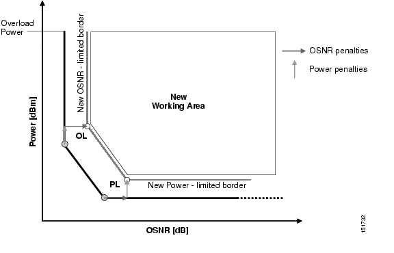
In the Cisco TransportPlanner interface model, the operative area of an interface is defined on a two-dimensional Cartesian plane where the x-axis is the optical signal-to-noise ratio (OSNR) value (dB) and y-axis is the receiver (Rx) power value (dBm). Three lines border the operative area. These lines are an approximation of the ISO-Bit Error Rate (BER) curve corresponding to the maximum BER tolerable by the interface:
•
On the original ISO-BER curve there are two points, OL and PL, that define the two main borders: OSNR limited (OL) and power limited (PL).
•
Figure D-1 shows the working area in an interface.
Figure D-1 Interface Operative Area
Signal impairments reduce the operative area of the interface. Because of signal distortion, higher OSNR and/or power on the Rx are required to get the same BER. When the power and OSNR margins are increased, OL and PL identify a new working area ( Figure D-2).
Figure D-2 Interface Margin Application
To define a third-party client interface, you enter parameters in Cisco TransportPlanner that build the working area and model its robustness to signal impairments such as dispersion, single interfering, Gaussian cross talk (Xt), etc. The input parameters follow:
•
–
–
–
–
–
–
•
•
•
–
–
–
–
–
•
•
•
•
Transmitter characteristics, bit rate, and back-to-back sensitivity parameters are required to create a third-party interface; the other parameters are optional. Cisco TransportPlanner checks your input to determine if the third-party interface could be modeled on a card type already present in the software. If the interface is not supported, TransportPlanner displays an error message. For the procedure to define third-party interfaces, see "2.2.4 Defining Third-Party DWDM Interfaces" section on page 2-25.
Scale Factors
The slope of the Q-factor (BER error function) curve versus OSNR or Rx power determines how a BER increase could be recovered with an increase of OSNR, power, or both depending in which OSNR/power working point the card is. In general, the scale factors are two values (one in OSNR and one in power) for each working point (OL and PL) of the interface model. If one is zero, it means that for that working point the BER is not sensitive to an increase. At least one factor must be different from zero.
The scale factors reflect the optical signal after it has passed through the maximum dispersion it can tolerate, because when the signal is more distorted the slope is higher and the factors are applied on impairments other than dispersion. As a result, the slope should be calculated at the OSNR and power of the OL and PL points with the dispersion margins added. Q-factor variation is 2 dB.
F-P(PL), F-P(OL), F-OSNR(PL), and F-OSNR(OL) values entered in Cisco TransportPlanner translate a Q-penalty (that is, a BER increase) into power and OSNR penalties. F-P(PL) and F-OSNR(PL) are evaluated in the PL working region, while F-P(OL) and F-OSNR(OL) are evaluated in the OL working region of the curve with the dispersion margins added.
The formulas follow:
•
•
•
•
Figure D-3 illustrates the increase in OSNR corresponding to a variation of the Q-factor equal to 2 dB.
Figure D-3 Q-Factor Curve
Single-Interfering Cross-Talk Penalty Measurement
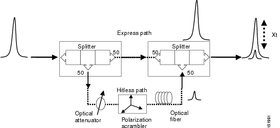
The single interfering cross-talk (Xt) measurement is shown in Figure D-4. The signal is split into two parts and recombined after one part has passed through attenuation, polarization scrambling, and linear transmission. The cross-talk calculation is the ratio between the two recombined signals. The attenuation allows different levels of cross-talk. The polarization scrambling measures the worst case of reciprocal polarization between the signal and its attenuated replica and the fiber to avoid phase coherence between signal and replica.
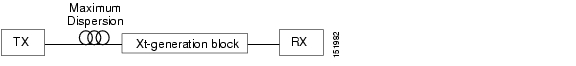
Because the penalty depends on the OSNR and power level, the measurement is calculated in the two working points OL and PL with the dispersion margin added. Consequently, a fiber with the maximum dispersion the interface can tolerate is placed between the transmitter and the splitter, as shown in Figure D-5. Transmission into the fiber should be linear (with channel power less than -10 dBm).
To calculate single-interfering cross-talk, you can input the coefficients for the exponential curves that estimate P-penalty(PL), P-penalty(OL), OSNR-penalty(PL), and OSNR-penalty(OL) for in the OL and PL regions of the interface model with dispersion margins added. The formula is Penalty(IXt) = A_SIXt* exp(B_SIXt* IXt).
Figure D-4 Generation Block for Single-Interfering Cross-Talk Measurement
Figure D-5 Block Diagram for Crosstalk Measure
Gaussian Cross-Talk Penalty Measurement
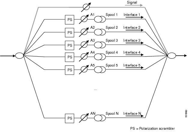
Cross-talk with Gaussian statistics can be simulated by recombining a high number of interfering signals. The interfering branch shown in Figure D-4 set up has to be replicated in order to obtain more interfering signals, as shown in Figure D-6. The signal is split into N parts and each part but one passes through an attenuator (from A1 to AN in Figure D-6), a polarization scrambler, and a spool of fiber. Ten interfering signals are enough to guarantee a good approximation of the Gaussian statistics. In case of the single interfering cross-talk, the penalty depends on the working point, OSNR/power, in which the card is working. The measurement should be done in the OL and PL with dispersion margin added with the maximum dispersion tolerable by the card, as shown in the block diagram of Figure D-5.
To calculate Gaussion cross-talk levels, you can enter the coefficients for the exponential curves that estimate P-penalty(PL), P-penalty(OL), OSNR-penalty(PL), and OSNR-penalty(OL) in the OL and PL regions of the interface model with dispersion margins added. The formula is Penalty(GXt) = A_GXt * exp(B_GXt *GXt).
Figure D-6 Generation Block for Gaussian Cross-Talk Measurement
![]()
![]()
![]()
![]()
![]()
![]()
![]()
![]()
Posted: Thu Oct 18 09:03:12 PDT 2007
All contents are Copyright © 1992--2007 Cisco Systems, Inc. All rights reserved.
Important Notices and Privacy Statement.