cc/td/doc/product/ong/600_sdh/sdh60014
hometocprevnextglossaryfeedbacksearchhelp
PDF

Table Of Contents

General Troubleshooting

Network Troubleshooting Tests

Identify Points of Failure on a Circuit Path

Perform a Facility/Payload Loopback on a Source STM-N Port

Perform an XC Loopback on a Source STM-N Port

Perform a Facility/Payload Loopback on a Destination STM-N Port

Restoring the Database to a Previous or Original Configuration

Node is Functioning Improperly or Has Incorrect Data

PC Connectivity Troubleshooting

Retrieve the Node Information

Unable to Ping Your PC

Browser Login Does Not Launch Java

Unable to Verify the NIC Connection on Your PC

TCP/IP Connection is Lost

CTC Operation Troubleshooting

Cisco Transport Controller Installation Wizard Hangs

Browser Stalls When Downloading JAR Files from TSC

Cisco Transport Controller Does Not Launch

Sluggish Cisco Transport Controller Operation or Login Problems

Node Icon is Gray on Cisco Transport Controller Network View

Unable to Launch Due to Applet Security Restrictions

Cisco Transport Controller Does Not Recognize the Node

Username or Password Mismatch

No IP Connectivity Exists Between Nodes

DCC Connection Lost

Loss of IP Communication Between Nodes on an OSPF LAN

Circuits and Timing

ONS 15600 SDH Switches Timing Reference

Holdover Synchronization Alarm

Free-Running Synchronization Mode

Daisy-Chained BITS Not Functioning

Fiber and Cabling

Bit Errors Appear for an Optical Traffic Card

Faulty Fiber-Optic Connections

Optical Traffic Card Transmit and Receive Levels

Power and LED Tests

Power Supply Problems

Lamp Test for Card LEDs

General Troubleshooting


This chapter provides procedures for troubleshooting the most common problems encountered when operating a CiscoONS15600SDH. To troubleshoot specific ONS15600SDH alarms, see Chapter2, "Alarm Troubleshooting." If you cannot find what you are looking for; contact the Cisco Technical Assistance Center (TAC). See the "Obtaining Technical Assistance" section .

This chapter begins with the following sections on network problems:

Network Troubleshooting Tests1.1—Describes loopbacks and hairpin circuits, which you can use to test circuit paths through the network or logically isolate faults.


Note For network acceptance tests, refer to the Cisco ONS 15600 SDH Procedure Guide.


Identify Points of Failure on a Circuit Path1.2—Explains how to perform the tests described in the "Network Troubleshooting Tests" section.

The remaining sections describe symptoms, problems, and solutions that are categorized according to the following topics:

Restoring the Database to a Previous or Original Configuration1.3—Provides troubleshooting for node operation errors that might require procedures to restore software data or to restore the node to the default setup.

PC Connectivity Troubleshooting1.4—Provides troubleshooting procedures for PC and network connectivity to the ONS15600SDH.

CTC Operation Troubleshooting1.5—Provides troubleshooting procedures for Cisco Transport Controller (CTC) login or operation problems.

Circuits and Timing1.6—Provides troubleshooting procedures for circuit creation, error reporting, and timing reference errors and alarms.

Fiber and Cabling1.7—Provides troubleshooting procedures for fiber and cabling connectivity errors.

1.1  Network Troubleshooting Tests

Use loopbacks to test newly created circuits before running live traffic or to logically locate the source of a network failure. All ONS15600SDH optical (STM-N) cards allow loopbacks.


Caution On optical cards, a loopback can only be applied to a port that is out of service to avoid traffic disruption.


A facility/payload loopback tests the line interface unit (LIU) of an STM-N port. After applying a facility/payload loopback on an STM-N port, use a test set to run traffic over the loopback. A successful facility/payload loopback isolates the LIU of the port as the potential cause of a network problem. Figure1-1 shows a facility/payload loopback on an STM-N port.

Figure 1-1 Facility/Payload Loopback Process on an STM-N Port

The payload loopback is similar to a facility loopback.The difference is that a payload loopback will terminate/regenerate section and line overhead and a facility loopback will pass through section and line overhead untouched. The STM16 card accomplishes a facility loopback by looping back the signal just before the framer chip. The STM64 card cannot do this, because of the differences in the design. To accomplish a loopback on the STM64 card, the loopback signal has to pass through the framer chip and will terminate/regenerate line and section overhead. Since line and section overhead on the STM64 card is terminated/regenerated, this is called a payload loopback.

A cross-connect loopback tests a circuit path as it passes through the Core Cross Connect (CXC) card and loops back to the port being tested. Figure1-2 shows a cross-connect loopback on an STM-N port. The test-set traffic comes in on the STM-N port, goes through the CXC card, and loops back to the STM-N port. This test verifies that the CXC card and circuit paths are valid, but does not test the LIU on the STM-N port.

Figure 1-2 Cross-Connect Loopback Process on an STM-N Port


Note When testing STM-64 signals with jitter analyzers, be sure to verify with the manufacturer that you are using the most current test equipment. Some test equipment has demonstrated false high jitter readings caused by accumulated jitter dependencies within the test equipment.


1.2  Identify Points of Failure on a Circuit Path

Facility/payload loopbacks and cross-connect loopback circuits are often used together to test the circuit path through the network or to logically isolate a fault. Performing a network test at each point along the circuit path systematically isolates possible points of failure. Using a series of facility/payload loopbacks and cross-connect loopbacks, the path of a circuit is traced and the possible points of failure are isolated.


Note Software Release 1.4 of the CiscoONS15600SDH supports only facility/payloadand cross-connect loopbacks. Terminal loopbacks are not supported.


A logical progression of network test procedures apply to this scenario:

1. A facility/payload loopback on the source STM-N port

2. A cross-connect (XC) loopback on the source STM-N port

3. A facility/payload loopback on the destination STM-N port


Note The test sequence for your circuits will differ according to the type of circuit and network topology.


Note All loopback tests require on-site personnel.


1.2.1  Perform a Facility/Payload Loopback on a Source STM-N Port

The facility/payload loopback test is performed on a port in a network circuit, in this example the circuit source STM-N port. Completing a successful facility/payload loopback on this port isolates the STM-N port as a possible failure point. Figure1-3 shows an example of a facility/payload loopback on a source STM-N port.

Figure 1-3 Facility/Payload Loopback on a Circuit Source STM-N Port

1.2.1.1  Create the Facility/Payload Loopback on the Source STM-N Port


Step1 Connect an optical test set to the port you are testing.


Note Refer to the manufacturer instructions for detailed information about connection and setup of the optical test set.


a. Use appropriate cabling to attach the transmit (Tx) and receive (Rx) terminals of the optical test set to the connectors for the port you are testing. The Tx and Rx terminals connect to the same port.

b. Adjust the test set accordingly.

Step2 Use CTC to create the facility/payload loopback on the port you are testing:

a. In card view, click the Maintenance > Loopback tabs.

b. Choose the appropriate loopback in the Loopback Type column for the port you are testing:

For an STM-16 card, select Facility (Line) in the Loopback Type column.

For an STM-64 card, select Payload in the Loopback Type column.

c. Click Apply .

d. Click Yes in the confirmation dialog box.

Step3 Continue with the "1.2.1.2Test the Facility/Payload Loopback Circuit" procedure.


1.2.1.2  Test the Facility/Payload Loopback Circuit


Step1 If the test set is not already sending traffic, send test traffic on the loopback circuit.

Step2 Examine the traffic received by the test set. Look for errors or any other signal information that the test set is capable of indicating.

Step3 If the test set indicates a good circuit, no further testing is necessary with the facility/payload loopback.

Clear the facility/payload loopback:

a. In card view, click the Maintenance > Loopback tabs.

b. Choose None in the Loopback Type column for the port you are testing.

c. Click Apply .

d. Click Yes in the confirmation dialog box.

Proceed to the "1.2.2  Perform an XC Loopback on a Source STM-N Port" procedure .

Step4 If the test set indicates:

a. A faulty circuit, the problem might be a faulty optical (STM-N) card.

b. A signal quality problem, check the optical power transmitted (OPT) parameter for an indication of a signal quality issue at the physical layer on the port.

Proceed to the "1.2.1.3  Test the Optical Card" procedure .


1.2.1.3  Test the Optical Card


Step1 Replace the suspect card with a known-good card. See the "Replace an STM-16 Card or STM-64 Card" procedure on page3-2 for details.

Step2 Reconnect the optical test set to the port you are testing.

Step3 Resend test traffic on the loopback circuit with a known-good card installed.

Step4 If the test set indicates a good circuit, the problem is probably a defective card.

Return the defective card to Cisco through the returned materials authorization (RMA) process. See the "Obtaining Technical Assistance" section   to contact the Cisco Technical Assistance Center (TAC).

Step5 Replace the faulty card. See the "Replace an STM-16 Card or STM-64 Card" procedure on page3-2 for details.

Step6 Clear the facility/payload loopback:

a. In card view, click the Maintenance > Loopback tabs.

b. Choose None in the Loopback Type column for the port you are testing.

c. Click Apply .

d. Click Yes in the confirmation dialog box.

Step7 Complete the "1.2.2Perform an XC Loopback on a Source STM-N Port" procedure.


1.2.2  Perform an XC Loopback on a Source STM-N Port

The XC loopback test is performed on the CXC card in a network circuit. An XC loopback circuit uses the same port for both source and destination. Completing a successful XC loopback through the CXC card isolates the possibility that the CXC card is the cause of the faulty circuit. Figure1-4 shows an example of an XC loopback on a source STM-N port.

Figure 1-4 XC Loopback on a Source STM-N Port

1.2.2.1  Create the XC Loopback on the Source STM-N Port


Step1 Connect an optical test set to the port you are testing.


Note Refer to the manufacturer instructions for detailed information on connection and setup of the optical test set.


a. If you just completed the "1.2.1  Perform a Facility/Payload Loopback on a Source STM-N Port" procedure , leave the optical test set hooked up to the STM-N port in the source node.

b. If you are starting the current procedure without the optical test set hooked up to the STM-N port, use appropriate cabling to attach the Tx and Rx terminals of the optical test set to the port you are testing. The Tx and Rx terminals connect to the same port.

c. Adjust the test set accordingly.

Step2 Use CTC to put the port you are testing out of service:

a. In node view, double-click the card where the test set is connected. The card view appears.

b. In card view, click the Provisioning > Line tabs.

c. Choose OOS_MT from the State column for the port you are testing.

d. Click Apply .

e. Click Yes in the confirmation dialog box.

Step3 Use CTC to set up the XC loopback on the circuit you are testing:

a. In card view, click the Provisioning > AU4 tabs.

b. Click the check box in the XC LoopBack column for the port you are testing.

c. Click Apply .

d. Click Yes in the confirmation dialog box.

Step4 Continue with the "1.2.2.2Test the XC Loopback Circuit" procedure


1.2.2.2  Test the XC Loopback Circuit


Step1 If the test set is not already sending traffic, send test traffic on the loopback circuit.

Step2 Examine the test traffic received by the test set. Look for errors or any other signal information that the test set is capable of indicating.

Step3 If the test set indicates a good circuit, no further testing is necessary with the cross-connect.

Clear the XC loopback:

a. In card view, click the Provisioning > AU4 tabs.

b. Uncheck the check box in the XC LoopBack column for the circuit you are testing.

c. Click Apply .

d. Click Yes in the confirmation dialog box.

Continue with the "1.2.3  Perform a Facility/Payload Loopback on a Destination STM-N Port" procedure .

Step4 If the test set indicates a faulty circuit, there might be a problem with the CXC card.

Step5 Continue with the "1.2.2.3Test the Alternate CXC Card" procedure.


1.2.2.3  Test the Alternate CXC Card


Step1 Do a manual data copy switch of the CXC cards before retesting the XC loopback circuit:

a. In node view, select the Maintenance > Preferred Copy tabs.

b. In the Set Preferred drop-down menu, select the alternate copy. (For example, if Copy B is preferred and in use, select Copy A.)


Note CTC CopyA refers to the CXC card in Slot 6. CopyB refers to the CXC card in Slot 8. Either copy can be chosen as the preferred copy CXC. The other CXC is called the alternate CXC in this chapter.


c. Click Apply .

d. Click Yes in the confirmation dialog box.


Note If you attempt a preferred copy switch and the switch is unsuccessful, a problem is present with the alternate CXC.


e. Click Refresh until the tab shows that the alternate copy you selected is now the preferred copy. The Currently Used field will show the newly selected preferred copy.

Step2 Resend test traffic on the XC loopback circuit.

The test traffic data now comes from the alternate CXC card.

Step3 If the test set indicates a faulty circuit, assume the CXC card is not causing the problem.

Clear the XC loopback:

a. In node view, double-click the card where the test set is connected. The card view appears.

b. In card view, click the Provisioning > AU4 tabs.

c. Uncheck the check box in the XC Loopback column for the circuit you are testing.

d. Click Apply .

e. Click Yes in the confirmation dialog box.

Continue with the "1.2.3  Perform a Facility/Payload Loopback on a Destination STM-N Port" procedure .

Step4 If the test set indicates a good circuit, the problem might be a defective card.

Step5 To confirm a defective preferred CXC card, continue with the "1.2.2.4Retest the Preferred CXC Card" procedure.


1.2.2.4  Retest the Preferred CXC Card


Step1 Do a manual data copy switch of the CXC cards before retesting the loopback circuit:

a. In node view, select the Maintenance > Preferred Copy tabs.

b. In the Set Preferred drop-down menu, select the alternate copy. (For example, if Copy B is preferred and in use, select Copy A.)

c. Click Apply .

d. Click Yes in the confirmation dialog box.


Note If you attempt a preferred copy switch and the switch is unsuccessful, a problem is present with the alternate CXC.


e. Click Refresh until the tab shows that the alternate copy you selected is now the preferred copy. The Currently Used field will show the newly selected preferred copy.

Step2 Resend test traffic on the loopback circuit.

Step3 If the test set indicates a faulty circuit, the problem is probably the defective card.

Return the defective card to Cisco through the RMA process. See the "Obtaining Technical Assistance" section   to contact the Cisco TAC.

Replace the defective CXC card. See the "Replace a CXC Card" procedure on page 3-1  for details.

Step4 If the test set indicates a good circuit, the CXC card might have had a temporary problem that was cleared by the data copy switch.

Step5 Clear the XC loopback:

a. In node view, double-click the card where the test set is connected. The card view appears.

b. In card view, click the Provisioning > AU4 tabs.

c. Uncheck the check box in the XC Loopback column for the circuit you are testing.

d. Click Apply .

e. Click Yes in the confirmation dialog box.

Step6 Continue with the "1.2.3Perform a Facility/Payload Loopback on a Destination STM-N Port" procedure.


1.2.3  Perform a Facility/Payload Loopback on a Destination STM-N Port

The facility/payload loopback test is performed on a port in a network circuit; in this example, the loopback is initiated on a circuit destination STM-N port. Completing a successful facility/payload loopback on this port isolates the possibility that the destination STM-N port is responsible for a faulty circuit. Figure1-5 shows an example of a facility/payload loopback on a destination STM-N port.

Figure 1-5 A Facility/Payload Loopback on a Destination STM-N Port

1.2.3.1  Create a Facility/Payload Loopback Circuit on a Destination STM-N Port


Step1 Connect an optical test set to the port you are testing:


Note Refer to the manufacturer instructions for detailed information on connection and setup of the optical test set.


a. If you just completed the "1.2.2  Perform an XC Loopback on a Source STM-N Port" procedure , move the optical test set to the destination STM-N port.

b. If you are starting the current procedure without the optical test set hooked up to the STM-N port, use appropriate cabling to attach the Tx and Rx terminals of the optical test set to the port you are testing. The Tx and Rx terminals connect to the same port.

c. Adjust the test set accordingly.

Step2 Use CTC to put the port you are testing out of service:

a. In node view, double-click the card where the test set is connected. The card view appears.

b. In card view, click the Provisioning > MS tabs.

c. Choose OOS_MT from the State column for the port you are testing.

d. Click Apply .

e. Click Yes in the confirmation dialog box.

Step3 Use CTC to create the facility/payload loopback on the port you are testing:

a. In card view, click the Maintenance > Loopback tabs.

b. Choose the appropriate loopback in the Loopback Type column for the port you are testing.

For an STM-16 card, select Facility (Line) in the Loopback Type column.

For an STM-64 card, select Payload in the Loopback Type column.

c. Click Apply .

d. Click Yes in the confirmation dialog box.

Step4 Continue with the "1.2.3.2Test the Facility/Payload Loopback Circuit" procedure.


1.2.3.2  Test the Facility/Payload Loopback Circuit


Step1 If the test set is not already sending traffic, send test traffic on the loopback circuit.

Step2 Examine the traffic received by the test set. Look for errors or any other signal information that the test set is capable of indicating.

Step3 If the test set indicates a good circuit, no further testing is necessary with the facility/payload loopback.

Clear the facility/payload loopback.

a. In card view, click the Maintenance > Loopback tabs.

b. Choose None in the Loopback Type column for the port you are testing:

c. Click Apply .

d. Click Yes in the confirmation dialog box.

Step4 If the test set indicates:

a. A faulty circuit, the problem might be a faulty optical (STM-N) card.

b. A signal quality problem, check the OPT parameter for an indication of a signal quality issue at the physical layer on the port.

Continue with the "1.2.3.3  Test the Optical Card" procedure .


1.2.3.3  Test the Optical Card


Step1 Replace the suspect card with a known-good card. See the "Replace an STM-16 Card or STM-64 Card" procedure on page3-2 for details.


Note Replacing a card disrupts traffic on all other ports on that card. Be sure all other traffic has been switched to a protect port on another card before replacing the card.


Step2 Reconnect the optical test set to the port you are testing.

Step3 Resend test traffic on the loopback circuit with a known-good card installed.

Step4 If the test set indicates a good circuit, the problem was probably the defective card.

Return the defective card to Cisco through the RMA process. See the "Obtaining Technical Assistance" section   to contact the Cisco TAC.

Replace the faulty card. See the "Replace an STM-16 Card or STM-64 Card" procedure on page 3-2  for details.

Step5 Clear the facility/payload loopback:

a. In card view, click the Maintenance > Loopback tabs.

b. Choose None in the Loopback Type column for the port you are testing.

c. Click Apply .

d. Click Yes in the confirmation dialog box.

The entire circuit path has now passed its comprehensive series of loopback tests. This circuit qualifies to carry live traffic.


1.3  Restoring the Database to a Previous or Original Configuration

This section contains troubleshooting for node operation errors that might require restoring software data or restoring the node to the default setup.

1.3.1  Node is Functioning Improperly or Has Incorrect Data

Symptom    One or more nodes are not functioning properly or have incorrect data.

Table1-1 describes the potential cause of the symptom and the solution.

Table 1-1 Node is Functioning Improperly or Has Incorrect Data 

Possible Problem
Solution

The node has an incorrect or corrupted database.

Complete the "1.3.1.1Restore the Database" procedure.


1.3.1.1  Restore the Database

The ONS15600SDH does not allow a database from one node to be restored to another node; however, a database from one node can be installed on another node in the network. A Configure Node option allows a database from one node to be installed on a different node.


Caution If you are restoring the database on multiple nodes, wait until the Timing and Shelf Controller (TSC) reboot has completed on each node before proceeding to the next node.


Note The following parameters are not backed up and restored: node name, IP address, mask and gateway, and Internet Inter-ORB Protocol (IIOP) port. If you change the node name and then restore a backed up database with a different node name, the circuits will map to the new renamed node. Cisco recommends keeping a record of the old and new node names.


Step1 In CTC, log into the node where you will restore the database.

a. On the PC connected to the ONS 15600 SDH, start Netscape or Internet Explorer.

b. In the Netscape or Internet Explorer Web address (URL) field, enter the ONS 15600 SDH IP address.

A Java Console window displays the CTC file download status. The web browser displays information about your Java and system environments. If this is the first login, CTC caching messages display while CTC files are downloaded to your computer. The first time you connect to an ONS 15600 SDH, this process can take several minutes. After the download, the CTC Login dialog box appears.

c. In the Login dialog box, type a user name and password (both are case sensitive) and click Login . The CTC node view window will appear.

Step2 Ensure that there are no ring switch events; for example, ring-switch east or west, and span-switch east or west. In network view, click the Conditions tab and click Retrieve to view a list of conditions.

Step3 If there are switch events that need to be cleared, in node (default) view, click the Maintenance > MS-SPRing tabs and view the West Switch and East Switch columns.

a. If there is a switch event (not caused by a line failure), clear the switch by choosing CLEAR from the drop-down menu and click Apply .

b. If there is a switch event caused by the Wait to Restore (WTR) condition, choose LOCKOUT SPAN from the drop-down menu and click Apply . When the LOCKOUT SPAN is applied, choose CLEAR from the drop-down menu and click Apply .

Step4 In node view, click the Maintenance > Database tabs.

Step5 Click Restore .

Step6 Locate the database file stored on the workstation's hard drive or on network storage.

Step7 Click the database file to highlight it.

Step8 Click Open . The Database Restore dialog box appears.


Caution Opening a restore file from another node or from an earlier backup might affect traffic on the login node.


Step9 Click Yes .

The Database Restore window monitors the file transfer.

Step10 Wait for the file to complete the transfer to the TSC card.

Step11 Click OK in the "Lost connection to node, changing to Network View" dialog box. Wait for the node to reconnect.

Step12 If you cleared a switch in Step3, reapply the switch as needed.


1.4  PC Connectivity Troubleshooting

This section contains troubleshooting procedures for PC and network connectivity to the ONS15600SDH.

1.4.1  Retrieve the Node Information

If you do not know the IP address of your ONS15600SDH network element (NE), you can obtain and view the NE information using a TL1 session.


Step1 Connect a three-pair swapping null modem adapter to the EIA/TIA-232 port on the customer access panel (CAP).

Step2 Connect a serial cable to the null modem adapter and to the serial port on your PC.

Step3 Configure the terminal emulation software (HyperTerminal):

a. Terminal emulation = vt100

b. Bits per second = 9600

c. Parity = None

d. Stop BITS = 1

e. Flow control = None

Step4 Press Enter . A prompt appears.

Step5 At the prompt, type the Activate User command to open a TL1 session:

ACT-USER::CISCO15:CTAG::PID;

Note When the semicolon is typed, the TL1 command is executed immediately.


Step6 At the prompt, type the Retrieve Network Element General command to retrieve the NE information:

RTRV-NE-GEN:::CTAG;

Step7 The response message will provide the following NE information.

IPADDR indicates the node IP address; IPADDR is a string.

IPMASK indicates the node IP mask; IPMASK is a string.

DEFRTR indicates the node default router; DEFRTR is a string.

NAME is the node name. The maximum name size is 20 characters; NAME is a string.

SWVER is the software version; SWVER is a string.

LOAD is the load version; LOAD is a string.

SELCLK is the system-wide selected clock/sync copy; SELCLK is of type DATA_CLK_COPY.

PREFCLK is the preferred clock/sync copy; PREFCLK is of type DATA_CLK_COPY.

SELDATA is the system-wide selected data copy; SELDATA is of type DATA_CLK_COPY.

PREFDATA is the preferred data copy; SELDATA is of type DATA_CLK_COPY.

Step8 At the prompt, type the Cancel User command to close the TL1 session:

CANC-USER::CISCO15:CTAG;

Step9 Remove the serial cable from the null modem adapter on the CAP and the serial port on your PC.

Step10 Remove the null modem adapter from the EIA/TIA-232 port on the CAP.


1.4.2  Unable to Ping Your PC

Symptom    When connecting your PC to the ONS 15600 SDH, you are unable to ping the IP address of your PC to verify the IP configuration.

Table1-2 describes the potential causes of the symptom and the solutions.

Table 1-2 Unable to Ping Your PC 

Possible Problem
Solution

The IP address was typed incorrectly.

Verify that the IP address used to ping the PC matches the IP address displayed in the Windows IP Configuration information retrieved from the system. See the "1.4.2.1Verify the IP Configuration of Your PC" procedure.

The IP configuration of your PC is not properly set.

To verify the IP configuration of your PC, refer to the "1.4.2.1Verify the IP Configuration of Your PC" procedure. If this procedure is unsuccessful, contact your network administrator for instructions to correct the IP configuration of your PC.


1.4.2.1  Verify the IP Configuration of Your PC


Step1 Open a DOS command window by selecting Start > Run from the Start menu on your PC.

Step2 In the Run window Open field, type command and then click OK . The DOS command window appears.

Step3 At the prompt in the DOS window, type one of the following commands:

For Windows 98, NT, or 2000, type ipconfig and press the Enter key.

For Windows 95, type winipcfg and press the Enter key.

The Windows IP configuration information appears, including the IP address, subnet mask, and default gateway.

Step4 At the prompt in the DOS window, type ping followed by the IP address you verified in Step3.

Step5 Press the Enter key to execute the command.

If the DOS window displays multiple (usually four) replies, the IP configuration is working properly.

If you do not receive a reply, your IP configuration might not be properly set. Contact your network administrator for instructions to correct the IP configuration of your PC.


1.4.3  Browser Login Does Not Launch Java

Symptom    The message "Loading Java Applet" does not appear and the JRE does not launch during the initial login.

Table1-3 describes the potential cause of the symptom and the solution.

Table 1-3 Browser Login Does Not Launch Java 

Possible Problem
Solution

The PC operating system and browser are not properly configured.

Reconfigure the PC operating system and the browser.

See the "1.4.3.1Reconfigure the PC Operating System and the Browser" procedure.


1.4.3.1  Reconfigure the PC Operating System and the Browser


Step1 From the Windows start menu, click Settings > Control Panel .

Step2 If Java Plug-in Control Panel does not appear, the JRE might not be installed on your PC.

a. Run the Cisco ONS 15600 SDH software CD.

b. Open the CD-drive:\Windows\JRE folder.

c. Double-click the j2re-1_3_1_02-win icon to run the JRE installation wizard.

d. Follow the JRE installation wizard steps.

Step3 From the Windows start menu, click Settings > Control Panel .

Step4 Double-click the Java Plug-in 1.3.1_02 icon.

Step5 Click Advanced on the Java Plug-in Control Panel.

Step6 From the Java Run Time Environment menu, choose JRE1.3inC:\ProgramFiles\JavaSoft\JRE\1.3.1_02 .

Step7 Click Apply .

Step8 In Communicator, click Edit > Preferences .

Step9 Click Advanced > Proxies > Direct connection to the Internet > OK .

Step10 Again on Communicator, click Edit > Preferences .

Step11 Click Advanced > Cache .

Step12 Confirm that the Disk Cache Folder field shows the following:

For Windows 95/98: C:\ProgramFiles\Netscape\Users\username\cache

For Windows NT/2000: C:\ProgramFiles\Netscape\username\Communicator\cache

Step13 If the Disk Cache Folder field is not correct, click Choose Folder .

Step14 Navigate to the file listed in Step12 and click OK .

Step15 Click OK in the Preferences window and exit the browser.

Step16 Temporarily disable any virus-scanning software on the computer. See the "1.5.2Browser Stalls When Downloading JAR Files from TSC" procedure.

Step17 Verify that the computer does not have two network interface cards (NICs) installed. If the computer does have two NICs, remove one.

Step18 Restart the browser and log into the ONS15600SDH.


1.4.4  Unable to Verify the NIC Connection on Your PC

Symptom    When connecting your PC to the ONS 15600 SDH, you are unable to verify that the NIC connection is working properly because the link LED is not illuminated or flashing.

Table1-4 describes the potential causes of the symptom and the solutions.

Table 1-4 Unable to Verify the NIC Connection on Your PC 

Possible Problem
Solution

The Category5 (CAT-5) cable is not plugged in properly.

Confirm that both ends of the cable are properly inserted. If the cable is not fully inserted because of a broken locking clip, replace the cable.

The Category5 cable is damaged.

Ensure that the cable is in good condition. If in doubt, use a known-good cable. Often, cabling is damaged due to pulling or bending.

Incorrect type of CAT-5 cable is being used.

CAP connection: To connect an ONS15600SDH directly to your laptop/PC or a router, use a cross-over CAT-5 cable. To connect the ONS15600SDH to a hub or a LAN switch, use a straight-through CAT-5 cable.

TSC connection: To connect an ONS15600SDH active TSC card directly to your laptop/PC, you can use either a straight-through or cross-over CAT-5 cable, because the RJ-45 port on the faceplate is autosensing.

For details on the types of CAT-5 cables, see the "1.7.2.2Crimp Replacement CAT-5 Cables" procedure.

The NIC is improperly inserted or installed.

If you are using a Personal Computer Memory Card International Association (PCMCIA) based NIC, remove and reinsert the NIC to make sure the NIC is fully inserted.

If the NIC is built into the laptop/PC, verify that the NIC is not faulty.

The NIC is faulty.

Confirm that the NIC is working properly. If you have no issues connecting to the network (or any other node), the NIC should be working correctly.

If you have difficulty connecting to the network (or any other node), the NIC might be faulty and needs to be replaced.


1.4.5  TCP/IP Connection is Lost

Symptom    The TCP/IP connection was established and then lost, and a DISCONNECTED alarm appears on CTC.

Table1-5 describes the potential cause of the symptom and the solution.

Table 1-5 TCP/IP Connection is Lost

Possible Problem
Solution

Your PC lost TCP/IP connection with the ONS15600SDH.

Use a standard ping command to verify the TCP/IP connection between the PC and the ONS15600SDH TSC card. A ping command will work if the PC connects directly to the TSC card or uses a LAN to access the TSC card. A ping command will also work if the CTC is connected via a gateway network element (GNE) and data communications channel (DCC) if the node and CTC are in the same subnet or the required static routes are configured.

See the "Ping the ONS15600SDH" procedure.


Ping the ONS 15600 SDH


Step1 Display the command prompt:

a. If you are using a Microsoft Windows operating system, from the Start Menu choose Run , type command in the Open field of the Run dialog box, and click OK .

b. If you are using a Sun Solaris operating system, from the Common Desktop Environment (CDE) click the Personal Application tab and click Terminal .

Step2 For both the Microsoft and Sun operating systems, type the following at the prompt:

ping ONS-15600-SDH-IP-address

For example:

ping 192.1.0.2.

If the workstation has connectivity to the ONS 15600 SDH, the ping is successful and displays a reply from the IP address. If the workstation does not have connectivity, a "Request timed out" message appears.

Step3 If the ping is successful, an active TCP/IP connection exists. Restart CTC.

Step4 If the ping is not successful, and the workstation connects to the ONS15600SDH through a LAN, verify that the workstation's IP address is on the same subnet as the ONS node.

If the ping is not successful and the workstation connects directly to the ONS 15600 SDH, verify that the link light on the workstation NIC is illuminated.


1.5  CTC Operation Troubleshooting

This section contains troubleshooting procedures for CTC login or operation problems.

1.5.1  Cisco Transport Controller Installation Wizard Hangs

Symptom    The Cisco Transport Controller Installation Wizard hangs or stalls during Netscape Communicator installation when installing the RealPlayer G2 plug-in application from the Cisco ONS 15600 SDH software or documentation CD-ROM.

Table1-6 describes the potential cause of the symptom and the solutions.

Table 1-6 Cisco Transport Controller Installation Wizard Hangs

Possible Problem
Solution

RealPlayer G2 is incompatible with the CTC Installation Wizard when it is installed with the Netscape Communicator software from the CD.

Abort the installation. See the "Abort the Stalled Installation Wizard" procedure.

Restart the CTC Installation Wizard and perform a custom Netscape Communicator installation that excludes RealPlayer G2 from the items being installed. Refer to the Cisco ONS 15600 SDH Procedure Guide to perform a custom installation that excludes RealPlayer G2.

Note The RealPlayer G2 software can be installed separately at a later time without affecting the other Cisco Transport Controller software.


Abort the Stalled Installation Wizard


Step1 Abort the stalled CTC Installation Wizard by pressing Ctrl+Alt+Del . The Windows Security dialog box appears.

Step2 In the Windows Security dialog box, click Task Manager .

Step3 In the Windows Task Manager dialog box, highlight the Cisco Transport Controller Installation Wizard and click the End Task button.

Step4 Click Yes in the confirmation dialog box.

Step5 Navigate to the drive containing the CTC CD-ROM and double-click setup.exe to restart the CiscoTransport Controller Installation Wizard.

Step6 Refer to the Cisco ONS 15600 SDH Procedure Guide to perform a custom Netscape Communicator installation that excludes RealPlayer G2 from the items to be installed.


1.5.2  Browser Stalls When Downloading JAR Files from TSC

Symptom    The browser stalls or hangs when downloading a Cisco Transport Controller JAR files from the TSC card.

Table1-7 describes the potential cause of the symptom and the solution.

Table 1-7 Browser Stalls When Downloading JAR Files from TSC 

Possible Problem
Solution

McAfee VirusScan software might be interfering with the operation. The problem occurs when the VirusScan Download Scan is enabled on McAfee VirusScan 4.5 or later.

Disable the VirusScan Download Scan feature. See the "1.5.2.1Disable the VirusScan Download Scanning" procedure.


1.5.2.1  Disable the VirusScan Download Scanning


Step1 From the Windows start menu, choose Programs > Network Associates > VirusScan Console .

Step2 Double-click the VShield icon listed in the VirusScan Console dialog box.

Step3 Click the Configure button on the lower part of the Task Properties window.

Step4 Click the Download Scan icon next to the System Scan Properties dialog box.

Step5 Uncheck the Enable Internet download scanning check box.

Step6 Click Yes when the warning message appears.

Step7 Click OK in the System Scan Properties dialog box.

Step8 Click OK in the Task Properties window.

Step9 Close the McAfee VirusScan window.


1.5.3  Cisco Transport Controller Does Not Launch

Symptom    CTC does not launch and usually an error message appears before the login screen appears.

Table1-8 describes the potential causes of the symptom and the solutions.

Table 1-8 Cisco Transport Controller Does Not Launch 

Possible Problem
Solution

The Communicator browser cache points to an invalid directory.

Redirect the Communicator cache to a valid directory. See the "1.5.3.1Redirect the Communicator Cache to a Valid Directory" procedure.

The user is connected to the standby TSC module.

Connect the login PC to the port on the front of the active TSC card; the active TSC has a green ACT LED illuminated.


1.5.3.1  Redirect the Communicator Cache to a Valid Directory


Step1 Launch Netscape Communicator.

Step2 Display the Edit menu.

Step3 Choose Preferences .

Step4 In the Category column on the left side, go to Advanced and choose the Cache tab.

Step5 Change your disk cache folder to point to the cache file location.

The cache file location is usually C:\ProgramFiles\Netscape\Users\yourname\cache. The yourname segment of the file location is often the same as the user name.


1.5.4  Sluggish Cisco Transport Controller Operation or Login Problems

Symptom    You experience sluggish CTC operation or have problems logging into CTC.

Table1-9 describes the potential cause of the symptom and the solution.

Table 1-9 Sluggish Cisco Transport Controller Operation or Login Problems 

Possible Problem
Solution

The CTC cache file is corrupted.

Delete the CTC cache file. This operation forces the ONS15600SDH to download a new set of JAR files to your computer hard drive. See the "1.5.4.1Delete the CTC Cache File Automatically" procedure or the "1.5.4.2Delete the CTC Cache File Manually" procedure.


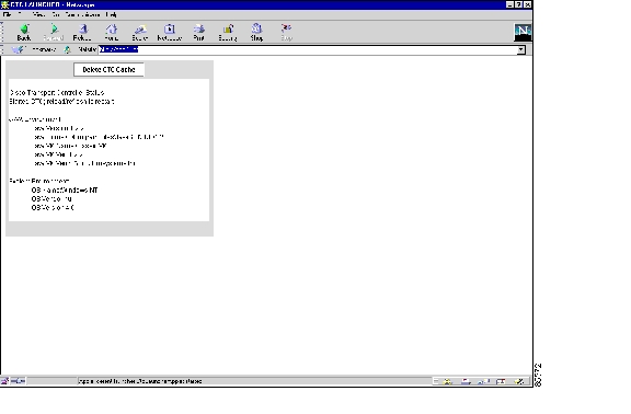
1.5.4.1  Delete the CTC Cache File Automatically


Step1 Enter an ONS15600SDH IP address into the browser URL field. The initial browser window shows a Delete CTC Cache button.

Step2 Close all open CTC sessions and browser windows. The PC operating system will not allow you to delete files that are in use.

Step3 Click the Delete CTC Cache button on the initial browser window to clear the CTC cache. Figure1-6 shows the Delete CTC Cache window.

Figure 1-6 The Delete the CTC Cache Window


1.5.4.2  Delete the CTC Cache File Manually


Step1 To delete the JAR files manually, from the Windows Start menu choose Search > For Files or Folders .

Step2 Enter *.jar in the Search for files or folders named field on the Search Results dialog box and click Search Now .

Step3 Click the Modified column on the Search Results dialog box to find the JAR files that match the date when you downloaded the files from the TSC. These files might include CTC*.jar, CMS*.jar, and jar_cache*.tmp.

Step4 Highlight the files and press the keyboard Delete key.

Step5 Click Yes in the confirmation dialog box.


1.5.5  Node Icon is Gray on Cisco Transport Controller Network View

Symptom    The CTC network view shows one or more node icons as gray in color and without a node name.

Table1-10 describes the potential causes of the symptom and the solutions.

Table 1-10 Node Icon is Gray on Cisco Transport Controller Network View 

Possible Problem
Solution

Different CTC releases do not recognize each other.

Usually accompanied by an INCOMPATIBLE-SW alarm. Incompatibility occurs on login nodes with compatible software that encounter other nodes in the network that have a newer software version.

Note In mixed platform networks (ONS 15600 SDH, and ONS 15454 SDH), you must log into CTC on an ONS 15600 SDH node to enable Operation, Administration, Maintenance, and Provisioning (OAM&P) of all nodes. ONS 15454 SDH Software Release 3.3 and earlier does not recognize ONS 15600 SDH nodes.

A username/password mismatch.

Usually accompanied by a NOT-AUTHENTICATED alarm. Correct the username and password as described in the "1.5.8Username or Password Mismatch" procedure.

No IP connectivity between nodes.

Usually accompanied by Ethernet-specific alarms. Verify the Ethernet connections between nodes.

A lost DCC connection.

Usually accompanied by an Embedded Operations Channels (EOC) alarm. Clear the EOC alarm and verify the DCC connection as described in the "EOC" alarm on page2-28.

Open Shortest Path First (OSPF) not properly configured

Usually accompanied by a HELLO failure. Reconfigure the OSPF on the system to proper settings.

CTC launched from ONS15454 SDH

You can manage an ONS15600SDH from an ONS15454SDH node if the CTC session is launched on the same CTC release or later. The ONS15600SDH CTC is compatible with ONS15454 SDH and CTC Software Release 3.3 CTC. Restart CTC and log into an ONS15600SDH node to enable node management.


1.5.6  Unable to Launch Due to Applet Security Restrictions

Symptom    The error message "Unable to launch CTC due to applet security restrictions" appears after you enter the IP address in the browser window.

Table1-11 describes the potential cause of the symptom and the solution.

Table 1-11 Unable to Launch Due to Applet Security Restrictions 

Possible Problem
Solution

You did not execute the javapolicyinstall.bat file, or the java.policy file might be incomplete.

1. Verify that you have executed the javapolicyinstall.bat file on the ONS15600SDH software CD. This file is installed when you run the CTC Setup Wizard. Refer to the CTC installation information in the Cisco ONS 15600 SDH Procedure Guide for instructions.

2. If you ran the javapolicyinstall.bat file but still receive the error message, you must manually edit the .java.policy file on your PC. See the "1.5.6.1Manually Edit the .java.policy File" procedure.


1.5.6.1  Manually Edit the .java.policy File


Step1 Search your computer for the .java.policy file and open it with a text editor (Notepad or Wordpad).

Step2 Verify that the end of this file has the following lines:

// Insert this into the system-wide or a per-user java.policy file. // DO NOT OVERWRITE THE SYSTEM-WIDE POLICY FILE--ADD THESE LINES!
grant codeBase "http://*/fs/LAUNCHER.jar" { permission java.security.AllPermission; };

Step3 If these five lines are not in the file, enter them manually.

Step4 Save the file and restart Communicator.

CTC should now start correctly.

Step5 If the error message is still reported, save the java.policy file as .java.policy. On Windows 95/98/2000 PCs, save the file to the C:\Windows folder. On Windows NT 4.0 PCs, save the file to all of the user folders on that PC, for example, C:\Winnt\profiles\joeuser.


1.5.7  Cisco Transport Controller Does Not Recognize the Node

Symptom    This situation is often accompanied by the INCOMPATIBLE-SW alarm.

Table1-12 describes the potential cause of the symptom and the solution.

Table 1-12 Cisco Transport Controller Does Not Recognize the Node 

Possible Problem
Solution

The software loaded on the connecting workstation and the software on the TSC card are incompatible.

Incompatibility occurs when the TSC software is upgraded but the PC has not yet upgraded to the compatible CTC JAR file. It also occurs on login nodes with compatible software that encounter other nodes in the network that have a later software version.

In mixed platform networks (ONS15600SDH and ONS15454SDH), you must log into the same or later CTC software release as the one loaded on the ONS15600SDH node to enable OAM&P of all nodes.

Note ONS 15454 SDH Software Releases 3.3 and earlier do not recognize ONS 15600 SDH nodes.


1.5.8  Username or Password Mismatch

Symptom    A mismatch often occurs concurrently with a NOT-AUTHENTICATED alarm.

Table1-13 describes the potential cause of the symptom and the solution.

Table 1-13 Username or Password Mismatch 

Possible Problem
Solution

The username or password entered do not match the information stored in the TSC.

All ONS SDH nodes must have the same username and password created to display every ONS SDH node in the network. You can also be locked out of certain ONS SDH nodes on a network if your username and password were not created on those specific ONS SDH nodes.

For initial login to the ONS15600SDH, type the CISCO15 user name in capital letters, type the otbu+1 password, and click Login .

See the "1.5.8.1Verify Correct User Name and Password" procedure.


1.5.8.1  Verify Correct User Name and Password


Step1 Ensure that your keyboard Caps Lock key is not turned on and affecting the case-sensitive entry of the user name and password.

Step2 Contact your system administrator to verify the user name and password.

Step3 Contact the Cisco TAC to create a new user name and password. See the "Obtaining Technical Assistance" section .


1.5.9  No IP Connectivity Exists Between Nodes

Symptom    The nodes have a gray icon, which is usually accompanied by alarms.

Table1-14 describes the potential causes of the symptom and the solutions.

Table 1-14 No IP Connectivity Exists Between Nodes 

Possible Problem
Solution

The node has lost DCC connection.

Usually accompanied by DCC termination alarms, such as EOC. Clear the EOC alarm and verify the DCC connection as described in the "EOC" alarm on page2-28.

The nodes are in different subnetworks and required static routes that are not provisioned.

Usually accompanied by DCC termination alarms. Properly provision required static routes and nodes in the same subnets. Refer to the procedure for setting up CTC access in the Cisco ONS 15600 SDH Procedure Guide.

OSPF is not properly configured.

Usually accompanied by OSPF Hello Fail alarms. Configure the OSPF to the proper settings. See the "HELLO" alarm on page2-43.


1.5.10  DCC Connection Lost

Symptom    A span between nodes on the network view is gray and/or the node is reporting DCC termination alarms, such as EOC.

Table1-15 describes the potential cause of the symptom and the solution.

Table 1-15 DCC Connection Lost 

Possible Problem
Solution

The DCC connection is lost.

Clear the EOC alarm and verify the DCC connection as described in the "EOC" alarm on page2-28.


1.5.11  Loss of IP Communication Between Nodes on an OSPF LAN

Symptom    The CTC session on an ONS 15600 SDH connected to router 1 loses communication with the ONS 15600 SDH connected to router 2 on the same LAN in OSPF backbone area 0.

Table1-16 describes the potential causes of the symptom and the solution.

Table 1-16 Loss of IP Communication in Segmented OSPF Area 

Possible Problem
Solution

The OSPF backbone area 0 has segmented into multiple GNEs.

If multiple ONS15600SDH nodes and routers are connected to the same LAN in OSPF backbone area 0 and a link between two routers breaks, the backbone OSPF area 0 could divide into multiple GNEs. If this occurs, the CTC session on the ONS node connected to router 1 will not be able to communicate with the ONS15600SDH connected to router 2. This is standard behavior for an OSPF network.

To resolve this problem, you must repair the link between the routers or provide another form of redundancy in the network. Refer to the Cisco ONS 15600 SDH Procedure Guide for procedures to repair the link between the routers.

A broken link between two routers on the LAN in OSPF backbone area0.


1.6  Circuits and Timing

This section provides solutions to circuit creation and reporting errors, as well as common timing reference errors and alarms.

1.6.1  ONS 15600 SDH Switches Timing Reference

Symptom    Timing references switch when one or more problems occur.

Table1-17 describes the potential causes of the symptom and the solutions.

Table 1-17 ONS 15600 SDH Switches Timing Reference 

Possible Problem
Solution

The optical or building integrated timing supply (BITS) input is receiving loss of signal (LOS), loss of frame (LOF), or alarm indication signal (AIS) from its timing source.

Clear the alarm and set up the timing source to a reliable source.

To clear an LOS (BITS) alarm, see the "LOS (BITS)" alarm on page2-54.

To clear an LOF (BITS) alarm, see the "LOF (BITS)" alarm on page2-52.

To clear an AIS (BITS) alarm, see the "AIS (BITS)" condition on page2-10.

Refer to the procedure for setting up timing in the Cisco ONS 15600 SDH Procedure Guide.

The following are the values:

0000—Quality Unknown

0010—G.811

0100—G.812 Transit

1000—G.812 Local

1011—Synchronous equipment timing source (SETS) ---> Internal Timing in the CTC

1111—Do not use for synchronization

The optical or BITS input is not functioning.

SSM message is set to DUS.

The Synchronization Status Message (SSM) Changed to Do Not Use for Synchronization (DUS) condition occurs when the synchronization status message quality level is changed to DUS.

The port that reports the condition is not at fault. The condition applies to the timing source. SSM-DUS prevents timing loops by providing a termination point for the signal usage.

To clear the SSM-DUS alarm, see the "SSM-DUS" condition on page2-76.

The input frequency is off by more than 15ppm.

Set up the timing input to a reliable timing source. Refer to the procedure for setting up timing in the Cisco ONS 15600 SDH Procedure Guide.

The input clock wanders and has more than three slips in 30seconds.

SSM_FAIL

External timing configuration:

Step Ext.1 Check the BITS configuration. If the T1 signal has been provisioned it is possible that the SSM quality message is not a legal value in OptionI synchronization network.

Step Ext.2 If the T1 has not been provisioned then check if there is some other alarm on the BITS. Check if the configuration is coherent with the input signal.

Line timing configuration:

Step Lin.1 Check if one of the ONS 15600 SDH is externally synchronized then perform the Step Ext.1

Step Lin.2 If ONS 15600 SDH node does not exist with the external configuration and T1 signal, check if the board and port has any problem as signal degraded or fibre error.

BPV Alarm

This alarm occurrs only when the 64kHz signal has been provisioned. Check if the input signal is correct (using a Test set) and that the externally synchronized node is correctly provisioned with the 64kHz signal.


1.6.2  Holdover Synchronization Alarm

Symptom    The clock is running at a different frequency than normal and the HLDOVRSYNC alarm appears. Holdover occurs when the node is provisioned for external or line timing and both of the provisioned references fail. The timing switches to the internal Stratum 3E clock on the TSC card.

Table1-18 describes the potential cause of the symptom and the solution.

Table 1-18 Holdover Synchronization Alarm 

Possible Problem
Solution

The primary and secondary reference inputs have failed.

This alarm is raised when the primary and secondary reference inputs fail. See the "HLDOVRSYNC" condition on page2-44 for a detailed description.

Note The ONS 15600 SDH supports holdover timing per Telcordia GR-436-CORE when provisioned for external timing.


1.6.3  Free-Running Synchronization Mode

Symptom    The clock is running at a different frequency than normal and the FRNGSYNC alarm appears. Free-running is reported when the node is running on the internal clock after a failure of the primary and secondary clock references.

Table1-19 describes the potential cause of the symptom and the solution.

Table 1-19 Free-Running Synchronization Mode 

Possible Problem
Solution

No reliable reference input is available.

The clock is using the internal oscillator as its only frequency reference. This occurs when no reliable, prior timing reference is available. See the "FRNGSYNC" condition on page2-42 for a detailed description.


1.6.4  Daisy-Chained BITS Not Functioning

Symptom    You are unable to daisy-chain the BITS.

Table1-20 describes the potential cause of the symptom and the solution.

Table 1-20 Daisy-Chained BITS Not Functioning 

Possible Problem
Solution

Daisy-chaining of the BITS is not supported on the ONS15600SDH.

Daisy-chaining BITS causes additional wander buildup in the network and is therefore not supported. Instead, use a timing signal generator to create multiple copies of the BITS clock and separately link them to each ONS15600SDH.

You cannot use BITSA and/or BITSB outputs when providing a clock source from BITSA and/or BITSB inputs. To provide BITSA and/or BITSB external outputs, the clock source must be derived from an optical input.


1.7  Fiber and Cabling

This section explains problems typically caused by cabling connectivity errors. It also includes instructions for crimping CAT-5 cable and lists the optical fiber connectivity levels.

1.7.1  Bit Errors Appear for an Optical Traffic Card

Symptom    An optical traffic card has multiple bit errors.

Table1-21 describes the potential causes of the symptom and the solutions.

Table 1-21 Bit Errors Appear for a Traffic Card 

Possible Problem
Solution

Faulty cabling

Bit errors on line (traffic) ports usually originate from cabling problems or low or high optical-line power levels. The errors can be caused by synchronization problems, especially if PJ (pointer justification) errors are reported. Moving cards into different error-free slots will isolate the cause. Use a test set whenever possible because the cause of the errors can be external cabling, fiber, or external equipment connecting to the ONS15600SDH. Troubleshoot cabling problems using the "Network Troubleshooting Tests" section . Troubleshoot low or high optical-line power levels using the "1.7.2Faulty Fiber-Optic Connections" procedure.

Low optical-line power

High optical-line power


1.7.2  Faulty Fiber-Optic Connections

Symptom    An optical (STM-N) card has multiple SDH alarms and/or signal errors.

Table1-22 describes the potential cause of the symptom and the solution.

Table 1-22 Faulty Fiber-Optic Connections 

Possible Problem
Solution

Faulty fiber-optic connections to the optical (STM-N) card.

Faulty fiber-optic connections can be the source of SDH alarms and signal errors. See the "1.7.2.1Verify Fiber-Optic Connections" procedure.


Warning Because invisible laser radiation may be emitted from the aperture of the port when no cable is connected, avoid exposure to laser radiation and do not stare into open apertures.


1.7.2.1  Verify Fiber-Optic Connections


Step1 Ensure that a single-mode fiber connects the ONS15600SDH optical (STM-N) port(s).

SM or SM Fiber should be printed on the fiber span cable. ONS 15600 SDH optical (STM-N) cards do not use multimode fiber.

Step2 Ensure that the Optical Gateway Interface (OGI) fiber connector is properly aligned and locked.

Step3 Verify that the single-mode fiber optical-line power level coming into the breakout panel is within the specified range:

a. Remove the Rx end of the suspect fiber.

b. Connect the Rx end of the suspect fiber to a fiber-optic power meter, such as a GN Nettest LP-5000.

c. Determine the power level of the fiber with the fiber-optic power meter.

d. Verify that the power meter is set to the appropriate wavelength for the optical (STM-N) card you are testing (either 1310 nm or 1550 nm depending on the specific card).

e. Verify that the power level falls within the range specified for the card; see the "Optical Traffic Card Transmit and Receive Levels" section  .

If the power level is within tolerance, the problem is with the fan-out cables or the optical (STM-N) card.

If the power level is too high, add the appropriate attenuation.

Step4 If the power level falls below the specified range:

a. Clean or replace the OGI fiber fan-out cables. If possible, do this for the optical (STM-N) card you are working on and the far-end card. Refer to the Cisco ONS 15600 SDH Procedure Guide for fiber cleaning procedures.

b. Clean the optical connectors on the card. If possible, do this for the optical (STM-N) card you are working on and the far-end card. Refer to the Cisco ONS 15600 SDH Procedure Guide for fiber cleaning procedures.

c. Replace the far-end transmitting optical (STM-N) card to eliminate the possibility of a degrading transmitter on the far-end optical (STM-N) card.

d. If the power level still falls below the specified range with the replacement fibers and replacement card, check for one of these three factors that attenuate the power level and affect link loss (LL):

Excessive fiber distance; single-mode fiber attenuates at approximately 0.5 dB/km.

Excessive number of fiber connectors; connectors take approximately 0.5 dB each.

Excessive number of fiber splices; splices take approximately 0.5 dB each.


Note These are typical attenuation values. Refer to the specific product documentation for the actual values or use an optical time domain reflectometer (OTDR) to establish precise link loss and budget requirements.


Step5 If no power level shows on the fiber, the fiber is bad or the transmitter on the STM-N port failed.

a. Check that the Tx and Rx fibers are not reversed. LOS and EOC alarms normally accompany reversed Tx and Rx fibers. Fixing reversed Tx and Rx fibers clears the alarms and restores the signal.

b. Clean or replace the OGI fiber fan-out cables. If possible, do this for both the STM-N port you are working on and the far-end STM-N port. Refer to the Cisco ONS 15600 SDH Procedure Guide for fiber cleaning procedures.

c. Retest the fiber power level.

d. If the replacement fiber still shows no power, replace the optical (STM-N) card.


Tip To prevent overloading the receiver, use an attenuator on the fiber between the STM-N port transmitter and the receiver. Place the attenuator on the receive transmitter of the STM-N ports. Refer to the attenuator documentation for specific instructions.


1.7.2.2  Crimp Replacement CAT-5 Cables

You can crimp your own CAT-5 cables for use with the ONS15600SDH. To connect the CAP of an ONS15600SDH directly to your laptop/PC or a router, use a straight-through CAT-5 cable. To connect the CAP of an ONS15600SDH to a hub or a LAN switch, use a cross-over CAT-5 cable. To connect an ONS15600SDH active TSC card directly to your laptop/PC, you can use either a straight-through or cross-over CAT-5 cable because the RJ-45 port on the faceplate is auto sensing.

Use a straight-through or cross-over cable to connect to the backplane Ethernet connections of an ONS15600SDH. Use a straight-through cable to connect to the faceplate connector of the ONS15600SDH TSC card. Use CAT-5 cable RJ-45 T-568B, Color Code (100Mbps), and a crimping tool. Figure1-7 shows the layout of an RJ-45 connector.

Figure 1-7 RJ-45 Pin Numbers

Figure1-8 shows the layout of a straight-through cable.

Figure 1-8 A Straight-Through Cable Layout

Table1-23 shows the straight-through cable pinout.

Table 1-23 Straight-Through Cable Pinout 

Pin
Color
Pair
Name
Pin

1

white/orange

2

Transmit Data +

1

2

orange

2

Transmit Data -

2

3

white/green

3

Receive Data +

3

4

blue

1

4

5

white/blue

1

5

6

green

3

Receive Data -

6

7

white/brown

4

7

8

brown

4

8


Figure1-9 shows the layout of a cross-over cable.

Figure 1-9 A Cross-Over Cable Layout

Table1-24 shows the cross-over cable pinout.

Table 1-24 Cross-Over Cable Pinout 

Pin
Color
Pair
Name
Pin

1

white/orange

2

Transmit Data +

3

2

orange

2

Transmit Data -

6

3

white/green

3

Receive Data +

1

4

blue

1

4

5

white/blue

1

5

6

green

3

Receive Data -

2

7

white/brown

4

7

8

brown

4

8


Note Odd-numbered pins always connect to a white wire with a colored stripe.


1.7.3  Optical Traffic Card Transmit and Receive Levels

Each optical traffic card has connectors on its faceplate that contain both transmit and receive ports. Table1-25 shows the optical power levels for the transmit and receive ports of the optical traffic cards.

Table 1-25 Optical Traffic Card Transmit and Receive Power Levels 

Optical (STM-N) Card
Rx (Min. to Max.)
Tx (Min. to Max.)

STM16 SR 1310

-18 to -3 dBm

-10 to -3 dBm

STM16 LR 1550

-28 to -9 dBm

-2 to +3 dBm

STM64 SR 1310

-11 to -1 dBm

-6 to -1 dBm

STM64 LR 1550

-22 to -9 dBm

+4 to +7 dBm


The CTC Maintenance > Transceiver tab shows the OPT and optical power received (OPR) levels.


Note CTC might show OPT levels at 1 dBm more or less than the actual card OPT level.


1.8  Power and LED Tests

This section provides the "Power Supply Problems" section and the "Lamp Test for Card LEDs" section .


Note For information about power consumption for nodes and cards, refer to the Cisco ONS 15600 SDH Reference Guide.


1.8.1  Power Supply Problems

Symptom    Loss of power or low voltage, resulting in a loss of traffic.

Table1-26 describes the potential causes of the symptom and the solution.

Table 1-26 Power Supply Problems

Possible Problem
Solution

A loss of power or low voltage reading.

The ONS15600SDH requires a constant source of DC power to properly function. Input power is -48 VDC. Power requirements range from -40.5VDC to -72VDC.

A newly installed ONS15600SDH that is not properly connected to its power supply will not operate. Power problems can be confined to a specific ONS15600SDH or affect several pieces of equipment on the site.

A loss of power or low voltage can result in a loss of traffic.

See the "1.8.1.1Isolate the Cause of Power Supply Problems" procedure.

An improperly connected power supply.


Caution Operations that interrupt power supply or short the power connections to the ONS15600SDH are service-affecting.


Warning The power supply circuitry for the equipment can constitute an energy hazard. Before you install or replace the equipment, remove all jewelry (including rings, necklaces, and watches). Metal objects can come into contact with exposed power supply wiring or circuitry inside the equipment. This could cause the metal objects to heat up and cause serious burns or weld the metal object to the equipment.


Warning Static electricity can damage electro-optical modules. While handling electro-optical module, wear a grounding wrist strap to discharge the static buildup. Wrist straps are designed to prevent static electricity damage to equipment.


1.8.1.1  Isolate the Cause of Power Supply Problems


Step1 If a single ONS15600SDH show signs of fluctuating power or power loss:

a. Verify that the -48 VDC power terminals are properly connected to the power distribution unit (PDU).

b. Verify that the power cable is in good condition.

c. Verify that the power cable connections are properly crimped.

d. Verify that 50A circuit breakers are used in the PDU.

e. Verify that the circuit breakers are not blown or tripped.

f. Verify that a rack-ground cable attaches to the frame-ground terminal (FGND) on the ONS 15600 SDH. Connect this cable to the ground terminal according to local site practice.

g. Verify that the DC power source has enough capacity to carry the power load.

h. If the DC power source is battery-based:

Check that the output power is high enough. Power requirements range from -40.5 VDC to -72 VDC.

Check the age of the batteries. Battery performance decreases with age.

Check for opens and shorts in batteries, which might affect power output.

If brownouts occur, the power load and fuses might be too high for the battery plant.

Step2 If multiple pieces of site equipment show signs of fluctuating power or power loss:

a. Check the uninterruptible power supply (UPS) or rectifiers that supply the equipment. Refer to the UPS manufacturer documentation for specific instructions.

b. Check for excessive power drains caused by other equipment, such as generators.

c. Check for excessive power demand on backup power systems or batteries when alternate power sources are used.


1.8.2  Lamp Test for Card LEDs

Symptom    The card LED will not light or you are unsure if the LEDs are working properly.

Table1-27 describes the potential cause of the symptom and the solution.

Table 1-27 Lamp Test for Card LEDs 

Possible Problem
Solution

An LED on the card has failed.

A lamp test verifies that all the card LEDs work. Run this diagnostic test as part of the initial ONS15600SDH turn-up, a periodic maintenance routine, or any time you question whether an LED is in working order.

See the "1.8.2.1Verify Card LED Operation" procedure.


1.8.2.1  Verify Card LED Operation


Step1 Determine which TSC card is active by checking the green ACT LED on the face of the card.

Step2 Press the LAMP button on the face of the active TSC card.

Step3 Ensure that all the LEDs on the cards in the shelf illuminate for several seconds.

Step4 If an LED does not illuminate, the LED might be faulty.

Return the defective card to Cisco through the RMA process. See the "Obtaining Technical Assistance" section   to contact Cisco TAC.


hometocprevnextglossaryfeedbacksearchhelp

Posted: Sat Feb 28 08:15:31 PST 2004
All contents are Copyright © 1992--2004 Cisco Systems, Inc. All rights reserved.
Important Notices and Privacy Statement.