cc/td/doc/product/ong/600_sdh/sdh60014
hometocprevnextglossaryfeedbacksearchhelp
PDF

Table Of Contents

Replace Hardware

Replace a CXC Card

Replace an STM-16 Card or STM-64 Card

Initiate a Force Switch on a 1+1 Port

Switch all SNCP Circuits on a Span

Initiate a Force Switch on an MS-SPRing Span

Clear a Force Switch on a 1+1 Port

Clear a Force Switch on a SNCP Span

Clear a Force Switch on a MS-SPRing Span

Replace a TSC Card

Replace the Air Filter

Replace a Fan Tray

Replace the Customer Access Panel

Remove a Power Distribution Unit

Replace the Power Distribution Unit

Replace Hardware


This chapter provides procedures for replacing CiscoONS15600SDH hardware.

Replace a CXC Card

Replace an STM-16 Card or STM-64 Card

Replace a TSC Card

Replace the Air Filter

Replace a Fan Tray

Replace the Customer Access Panel

Remove a Power Distribution Unit

Replace the Power Distribution Unit

3.1  Replace a CXC Card


Warning Do not reach into a vacant slot or chassis while you install or remove a module or a fan. Exposed circuitry could constitute an energy hazard.


Note The ONS15600SDH system dynamically changes the preferred copy status from one Core Cross Connect (CXC) to the redundant copy if an error is detected on a card port. You can see this change in the Cisco Transport Controller (CTC) node view Maintenance>PreferredCopy window Currently Used field. If errors are detected on both CXC copies, the CurrentlyUsed field says Both.


Note You do not need to make any changes to the database if you are replacing it with a card of exactly the same type.


Note Card removal raises an improper removal (IMPROPRMVL) alarm, but this clears after the card replacement is complete.


Step 1 Log into the node where you will replace the CXC card. If necessary, refer to the CiscoONS15600SDH Procedure Guide for a login procedure.

Step 2 Physically remove the card to be replaced from the ONS15600SDH shelf:

a. Open the card ejectors.

b. Slide the card out of the slot.

Step 3 Physically replace the CXC card in the shelf:

a. Open the ejectors on the replacement card.

b. Slide the replacement card into the slot along the guide rails until it contacts the backplane.

c. Close the ejectors.


Note When you replace a card with an identical type of card, you do not need to make any changes to the database.


3.2  Replace an STM-16 Card or STM-64 Card


Warning Do not reach into a vacant slot or chassis while you install or remove a module or a fan. Exposed circuitry could constitute an energy hazard.


Note Card removal raises an improper removal (IMPROPRMVL) alarm, but this clears after the card replacement is completed.


Step 1 Log into the node where you will replace the STM-16 or STM-64 card. If necessary, refer to the CiscoONS15600SDH Procedure Guide for a login procedure.

Step 2 Ensure that the card you are replacing does not carry traffic in a 1+1 protection group:

a. In node view, click the Maintenance > Protection tabs.

b. Choose the first group listed under Protection Groups.

c. Verify that the slot number for the card you are replacing does not appear in the Selected Groups list. For example, if you are replacing the STM-16 card in Slot 3, make sure that Selected Groups does not contain any entries that start with s3, regardless of the port.

d. Repeat Steps b  and c  for each protection group.

e. If any of the groups contain a port on the card you want to replace, complete the "3.2.1  Initiate a Force Switch on a 1+1 Port" procedure .

Step 3 Ensure that the card you are replacing does not carry subnetwork connection protection (SNCP) circuit traffic.


Note A port can be part of a 1+1 protection group or part of a SNCP, but it cannot be configured for both. However, different ports on one card can be configured in different ways. If you move all of the traffic off some 1+1 ports, you still need to check whether the remaining ports are carrying SNCP traffic.


a. From the View menu, choose Go to Parent View .

b. Click the Circuits tab.

c. View the circuit source and destination ports and slots. If any circuits originate or terminate in the slot containing the card you are replacing, perform the "3.2.2  Switch all SNCP Circuits on a Span" procedure .


Note If the card you are replacing is not configured for any port or circuit protection, but does carry traffic, bridge and roll this traffic onto another card. Follow the "Bridge and Roll Traffic" procedure in the CiscoONS15600SDH Procedure Guide.


Step 4 Ensure that the card you are replacing does not carry multiplex section-shared protection ring (MS-SPRing) circuit traffic.

a. In the CTC node view, click View > Go to Parent View .

b. Click the Circuits tab.

c. View the circuit source and destination ports and slots. If any circuits originate or terminate in the slot containing the card you are replacing, perform the "3.2.3  Initiate a Force Switch on an MS-SPRing Span" procedure .


Note If the card you are replacing is not configured for any port or circuit protection, but does carry traffic, bridge and roll this traffic onto another card. Follow the "Bridge and Roll Traffic" procedure in the CiscoONS15600SDH Procedure Guide.


Step 5 Remove any fiber optic cables from the ports.

Step 6 Physically remove the card that you want to replace from the ONS15600SDH shelf:

a. Open the card ejectors.

b. Slide the card out of the slot.

Step 7 Physically replace the STM-16 or STM-64 card in the shelf:

a. Open the ejectors on the replacement card.

b. Slide the replacement card into the slot along the guide rails until it contacts the backplane.

c. Close the ejectors.


Note When you replace a card with an identical type of card, you do not need to make any changes to the database.


Step 8 Clear the Force switches:

To clear 1+1 Force switches, complete the "3.2.4  Clear a Force Switch on a 1+1 Port" procedure .

To clear SNCP Force switches, complete the "3.2.5  Clear a Force Switch on a SNCP Span" procedure .

To clear MS-SPRing Force switches, complete the "3.2.6  Clear a Force Switch on a MS-SPRing Span" procedure .

Step 9 When the card is in service and receiving traffic, reset the card's physical receive power level threshold in CTC:

a. Double-click the newly installed card in CTC node view.

b. Click the Provisioning > Threshold tabs.

c. Click the Physical radio button.

d. Click Set OPR for each port on the card.


3.2.1  Initiate a Force Switch on a 1+1 Port

This procedure switches 1+1 protection group traffic from one port in the group to the other using a Force switch.


Caution The Force command overrides normal protective switching mechanisms. Applying this command incorrectly can cause traffic outages.


Caution Traffic is not protected during a Force protection switch.


Note A Force switch will switch traffic even if the path has signal degrade (SD) or signal fail (SF) conditions; a Manual switch will switch traffic if the path has an error rate less than the signal degrade. A Force switch has a higher priority than a Manual switch.


Step 1 In node view, click the Maintenance > Protection tabs.

Step 2 In the Protection Groups area, select the protection group with the port you want to switch.

Step 3 In the Selected Groups area, select the port belonging to the card you are replacing. For example, if the card you are replacing contains the protect/standby port, click this port.

Step 4 Click Force .

Step 5 If the switch is successful, the group will say either FORCE TO WORKING or FORCE TO PROTECT.

Step 6 Return to the "3.2Replace an STM-16 Card or STM-64 Card" procedure.


3.2.2  Switch all SNCP Circuits on a Span

This procedure switches all circuits in an SNCP from the working span to the protect. It is used to remove traffic from a card that originates or terminates SNCP circuits.


Caution The Force command overrides normal protective switching mechanisms. Applying this command incorrectly can cause traffic outages.


Caution Traffic is not protected during a Force protection switch.


Step 1 In network view, click the Circuits tab.


Note To move from the node view to the network view, choose Go to Network View from the View menu.


Step 2 Record, print, or export the list of circuits from this tab, and mark the circuits that originate or terminate at the slot containing the card you are replacing.

For information about doing this from CTC, refer to the procedures in the Cisco ONS 15600 SDH Procedures Guide.

Step 3 In the network map, right-click a circuit connected to the node where you are performing the Force switch. Choose Circuits from the shortcut menu.

The Circuits window appears.

Step 4 Verify that this list contains the same circuits that you marked in the list.

Step 5 Choose Force from the drop-down menu at the bottom of the window.

If the switch was successful, all circuits will show FORCE in the Switch State column.

Step 6 Return to the "3.2Replace an STM-16 Card or STM-64 Card" procedure.


3.2.3  Initiate a Force Switch on an MS-SPRing Span

This procedure switches all circuits in a MS-SPRing to another span. It is used to remove traffic from a card that originates or terminates MS-SPRing circuits.


Caution The Force command overrides normal protective switching mechanisms. Applying this command incorrectly can cause traffic outages.


Caution Traffic is not protected during a Force protection switch.


Step 1 In the network view, click the Provisioning > MS-SPRing tabs.


Note To move from node view to network view, choose Go to Network View from the View menu.


Step 2 Click Edit .

Step 3 To apply a Force switch to the west line:

a. Right-click the west MS-SPRing port where you want to switch the MS-SPRing traffic and choose Set West Protection Operation .


Note If node icons overlap, drag and drop the icons to a new location. You can also return to network view and change the positions of the network node icons (MS-SPRing node icons are based on the network view node icon positions).


Note For two-fiber MS-SPRings, the squares on the node icons represent the MS-SPRing working and protect channels. You can right-click either channel.


b. In the Set West Protection Operation dialog box, choose FORCE RING from the drop-down menu. Click OK .

c. Click Yes in the two Confirm MS-SPRing Operation dialog boxes that appear.

On the network graphic, an F appears on the working MS-SPRing channel where you invoked the protection switch. The span lines change color to reflect the switched traffic. Green span lines indicate the new MS-SPRing path, and the lines between the protection switch are purple.

Performing a Force switch generates several conditions including FORCED-REQ-RING and WKSWPR.

Step 4 To apply a Force switch to the east line:

a. Right-click the east MS-SPRing port and choose Set East Protection Operation .


Note If node icons overlap, drag and drop the icons to a new location. You can also return to network view and change the positions of the network node icons. (MS-SPRing node icons are based on the network view node icon positions.)


Note For two-fiber MS-SPRings, the squares on the node icons represent the MS-SPRing working and protect channels. You can right-click either channel.


b. In the Set East Protection Operation dialog box, choose FORCE RING from the drop-down menu. Click OK .

c. Click Yes in the two Confirm MS-SPRing Operation dialog boxes that appear.

On the network graphic, an F appears on the working MS-SPRing channel where you invoked the protection switch. The span lines change color to reflect the switched traffic. Green span lines indicate the new MS-SPRing path, and the lines between the protection switch are purple.

Performing a Force switch generates several conditions including FORCED-REQ-RING and WKSWPR.

Step 5 From the File menu, choose Close .

Step 6 Return to the "3.2Replace an STM-16 Card or STM-64 Card" procedure.


3.2.4  Clear a Force Switch on a 1+1 Port

This procedure clears a Force switch on a 1+1 protection group port.


Note If the ports terminating a span are configured as revertive, clearing a Force switch to protect (or working) moves traffic back to the working (or protect) port. If ports are not configured as revertive, clearing a Force switch to protect does not move traffic back.


Step 1 In node view, click the Maintenance > Protection tabs.

Step 2 In the Protection Groups area, choose the protection group containing the port you want to clear.

Step 3 In the Selected Group area, choose the port you want to clear.

Step 4 In the Inhibit Switching area, click Clear .

Step 5 Click Yes in the confirmation dialog box.

The Force switch is cleared. Traffic will revert to the original port if the group was configured for revertive switching.

Step 6 Return to the "3.2Replace an STM-16 Card or STM-64 Card" procedure.


3.2.5  Clear a Force Switch on a SNCP Span

This procedure clears a SNCP Force switch. It reverts traffic to the original circuits after the card has been serviced.


Note If the ports terminating a span are configured as revertive, clearing a Force switch to protect (or working) moves traffic back to the working (or protect) port. If ports are not configured as revertive, clearing a Force switch to protect does not move traffic back.


Step 1 In network view, right-click the span that you switched. Choose Circuits from the shortcut menu.

The Circuits window appears.


Note To move from node view to network view, choose Go to Network View from the View menu.


Step 2 Choose Clear from the drop-down menu at the bottom of the window.

The Force switch is cleared.


Note Active circuits appear green in the Circuits window; standby circuits appear purple.


Note If these circuits are configured for revertive switching, they will revert to their original paths after the revertive time expires. If they are not revertive, they will not revert unless you switch them back. If the switch state is clear, you can complete the "3.2.2Switch all SNCP Circuits on a Span" procedure again to switch traffic back to the original path.


Step 3 Return to the "3.2Replace an STM-16 Card or STM-64 Card" procedure.


3.2.6  Clear a Force Switch on a MS-SPRing Span

This procedure clears a MS-SPRing Force switch. It reverts traffic to the original circuits after the card has been serviced.


Step 1 In network view, click the Provisioning > MS-SPRing tabs.


Note To move from node view to network view, choose Go to Network View from the View menu.


Step 2 Click Edit .

Step 3 To clear a Force switch on the west line:

a. Right-click the MS-SPRing west port where you want to clear the protection switch and choose Set West Protection Operation . Ports with a Force switch applied are marked with an F.

b. In the Set West Protection Operation dialog box, choose CLEAR from the drop-down menu. Click OK .

c. In the Confirm MS-SPRing Operation dialog box, click Yes .

Step 4 To clear a Force switch on the east line:

a. Right-click the MS-SPRing east port where you want to clear the protection switch and choose Set East Protection Operation . Ports with a Force switch applied are marked with an F.

b. In the Set East Protection Operation dialog box, choose CLEAR from the drop-down menu. Click OK .

c. In the Confirm MS-SPRing Operation dialog box, click Yes .

On the MS-SPRing network graphic, a green and a purple span line connects each node. This is the normal display for MS-SPRings when protection operations are not invoked.

Step 5 From the File menu, choose Close .

Step 6 Return to the "3.2Replace an STM-16 Card or STM-64 Card" procedure.


3.3  Replace a TSC Card


Warning Do not reach into a vacant slot or chassis while you install or remove a module or a fan. Exposed circuitry could constitute an energy hazard.


Note When an error is detected on a TSC card, the ONS15600SDH system switches control to the second TSC card; therefore, it should not be necessary to change control when you replace the card.


Note You do not need to make any changes to the database if you are replacing it with a card of exactly the same type.


Note Card removal raises an improper removal (IMPROPRMVL) alarm, but this clears after the card replacement is completed.


Step 1 Log into the node where you will replace the TSC card. If necessary, refer to the CiscoONS15600SDH Procedure Guide for a login procedure.

Step 2 To ensure that the card you are replacing is not the active TSC card, run the mouse over the card in CTC. If the popup for the card says Active, switch it to Standby:

a. Right-click the active TSC card to reveal the shortcut menu.

b. Click Soft-reset Card .

c. Click Yes when the confirmation dialog box appears.

d. Click OK when the "Lost connection to node, changing to Network View" dialog box appears.


Note The TSC card takes several minutes to reboot. Refer to the CiscoONS15600SDH Procedure Guide for more information about LED behavior during TSC card reboots.


Note Whenever TSC cards are changed from active to standby, it takes approximately 12 minutes to completely synchronize to the new system clock source due to the more accurate Stratum3E timing module being adopted.


Step 3 Confirm that the TSC card you reset is in standby mode after the reset.

A TSC card that is ready for service has a green SRV LED illuminated. An active TSC card has a green ACT STBY LED illuminated, but a standby card does not have this LED illuminated.


Tip If you run the cursor over the TSC card in CTC, a popup displays the card's status (whether active or standby).


Step 4 Physically remove the card you want to replace from the ONS15600SDH:

a. Open the card ejectors.

b. Slide the card out of the slot.

Step 5 Insert the replacement TSC card into the empty slot:

a. Open the ejectors on the replacement card.

b. Slide the replacement card into the slot along the guide rails until it contacts the backplane.

c. Close the ejectors.

Step 6 If you want to make the replaced TSC card active, complete Steps b through d again.


3.4  Replace the Air Filter


Warning Do not reach into a vacant slot or chassis while you install or remove a module or a fan. Exposed circuitry could constitute an energy hazard.


Caution Do not begin this procedure until you have a replacement filter at hand, ready for insertion.


Note The filter should be replaced approximately every 30 days with a new, clean filter.


Step 1 If the ONS15600SDH has a front door installed, open the front door:

a. Lift the latch and pull.

b. Swing the door open.

Step 2 Lift the door off its hinge pins and remove it. Set the door aside so you can reinstall it after you complete this procedure.

If the shelf does not have a front door installed, proceed to Step 3 .

Step 3 Locate the air filter. It is in the top of the shelf, above the three fan trays. Figure3-1 illustrates a shelf with one fan unit pulled out. The air filter is located in the internal filter bracket above the fans.

Figure 3-1 Air Filter With One Fan Unit Pulled Out

Step 4 Grasp the D-ring handle of the filter and pull it upward about 1/4 inch, being careful not dislodge any dust that might have collected on the filter.

Step 5 Slide the old filter past the indentations inside each side of the shelf that secure it in place.

Step 6 Continue pulling the filter straight up and then use both hands to gently slide the filter out of the shelf. Be careful not to dislodge any dust that might have collected on the filter.

Step 7 Position the new filter correctly. The D-ring handle should be on top and facing toward you. The foam should be facing upward, and the metal mesh should be facing downward.

Step 8 Slide the new air filter over the diagonal tracks in the compartment above the fan trays. Push it all the way back.

Step 9 Push the filter downward inside the tray, past the indentations inside each side of the shelf that secure the filter in place. The filter clicks into place.


3.5  Replace a Fan Tray


Caution Do not force a fan tray into place. Forcing a fan tray can damage the connectors on the fan tray or the connectors on the back panel of the shelf assembly.


Caution The center fan tray (Tray 2) in the ONS15600SDH shelf is the most critical tray because it cools the common control cards. If both fans in this tray are inoperative, CTC initiates a five-minute countdown to shut down one of the CXC cards. You should swap a working fan tray (Tray 1 or 3) with Tray 2 as soon as possible to prevent equipment damage.


The ONS15600SDH system requires at least one working fan in each of the three fan trays. When a single fan in a tray fails, Cisco recommends replacing the tray with a fully working tray as soon as practicable. To replace a fan tray, it is not necessary to move any of the cable management facilities.


Note Each fan tray contains two fans. The FAN LED indicates if one or both fans fail in a fan tray.


Step 1 Lift the latch on the fan tray that you want to replace, and pull the fan tray away from the shelf assembly.


Caution When a fan tray is removed from a shelf assembly, it momentarily creates the same situation that occurs if two fans in a single tray fail. In this situation (that is, the system is running on two fans), CTC software begins a five-minute countdown before shutting down CXC card operation in order to protect the cards. Replace the fan tray into the shelf assembly as quickly as possible to avoid CXC card shutdown.


Step 2 Insert the new fan tray in the shelf assembly.

Step 3 Press the latch down to secure the fan tray.


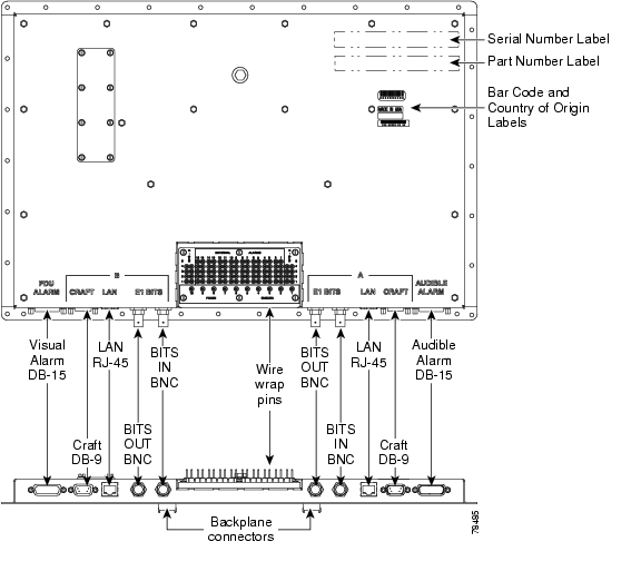
3.6  Replace the Customer Access Panel

To maintain network connectivity when changing the customer access panel (CAP_, move the Ethernet cable from the CAP LAN port to the LAN port on the active TSC card.


Step 1 Remove any tie wraps and cables attached to the CAP ( Figure3-2).

Figure 3-2 CAP Faceplate and Connections

Step 2 Label and remove the wire-wrap pin field wires from the CAP and move the wires aside.

Step 3 To remove the CAP:

a. Remove the 14 screws on the left and right sides of the CAP using a 3/16-in. socket.

b. Remove the 17 nuts on the top and bottom of the CAP using a 1/4-in. socket.

c. Loosen the center bolt using a 7/16-in. socket. This creates an extraction force on the connectors to successfully unmate them.

d. Pull the CAP off of the alignment pins.

Step 4 Place the replacement CAP over the alignment pins on the backplane and tighten the center bolt using a 7/16-in. socket. This creates an insertion force that successfully mates the connectors.

Step 5 Verify that the CAP cover is contacting the rear cover around the CAP perimeter.

Step 6 Replace the CAP screws and tighten to the specified torque (6 to 7 ft-lb).

Step 7 Replace the wire-wrap wires on the pin field according to their labeled positions.

Step 8 Replace the tie wraps and cables.


3.7  Remove a Power Distribution Unit

This procedure removes the ONS15600SDH power distribution unit (PDU).


Note The PDU can be ordered in entirety (including PDU-A, PDU-B, and alarm panel) or by part.


Step 1 Remove a PDU from a donor unit:

a. Secure an ESD-safe area to place dismounted equipment.

b. Working on the front of the donor unit, remove the donor PDU alarm unit from the center of the PDU:

Use a slot screwdriver to loosen the front two screws on the PDU alarm unit until they click.

Remove the alarm unit from the cabinet by pulling it straight out. Place it in an ESD-safe area.

c. Remove the donor PDU:

Remove the 1/4-in. nut and washer from frame ground lug on back side.

Use a slot screwdriver to loosen the front two screws on the PDU until they click.

Remove the PDU from the cabinet by pulling it straight out. Place it in an ESD-safe area.

Step 2 Disconnect the faulty PDU:


Note Wiring positions are mirrored for PDU-A and PDU-B (with the exception of the frame ground wire) and are marked on the top face of the PDU.


a. Disconnect DC power to the PDU to be replaced. For more information about bay power connections, refer to the Cisco ONS 15600 SDH Procedure Guide.

b. Working on the side of the PDU, use a voltage meter to verify that there is no DC power present at the terminals, using the procedure in the Cisco ONS 15600 SDH Procedure Guide.

c. Secure an ESD-safe area to place dismounted equipment.

d. Working on the side of the bay, use the 9/64-in. Allen wrench to loosen the two socket-head screws holding the plastic safety cover over the power terminals.

e. Remove the side plastic safety cover and screw down the socket-head screws by hand far enough for the PDU to clear the chassis when removed.


Note If socket-head screws are left partially screwed outward, the PDU cannot be removed from the chassis.


f. Working on the side of the bay, remove the electrical wiring of the faulty PDU:


Note In this procedure, all wiring screw post positions are referenced from right to left, starting with screw post 1 being the closest to the rear.


Use a 3/8-in. socket and wrench or socket driver to remove the green ground wire from the first vertical pair of screw posts.

Remove the jumper cable from the frame to logic ground terminals.

Remove the red 48-VDC power return wire from the third pair of screw posts.

Remove the black 48-VDC power supply wire from the fourth pair of screw posts.


Note Looking at the back of the power unit from the rear of the bay, there are three areas of screw posts on the rear of the unit: (1) the top 12 screw posts hold the busbars; (2) the right-bottom (PDU-A) or left-bottom (PDU-B) three screw posts hold the black frame ground, and (3) the bottom-left (PDU-A) or bottom-right (PDU-B) six screw posts hold the green frame and logic grounds.


g. Working on the rear of the bay, remove the two thumbnuts holding the plastic safety cover. Remove the plastic safety cover.

h. Working on the rear of the power unit with the six bottom-left (PDU-A) or bottom-right (PDU-B) screw posts, remove the nuts, washers, frame and logic ground wires. Use a 7/16-in. socket on the nuts, and needle-nose pliers to remove the star washers.


Note Wiring positions are mirrored for PDU-A and PDU-B with the exception of the green frame ground wire to the rear of the bay.


i. Working on the rear of the bay with the top 12 screw posts, use a 7/16-in. socket and socket driver to remove the last four nuts holding PDU-B to the top-bay busbar. Use needle-nose pliers to remove the star washers.

j. Remove the 1/4-in. nut and washer from the frame ground lug.

Step 3 Working on the front of the bay, remove the faulty PDU:

a. Use a slot screwdriver to unscrew the two PDU slot screws until they click.

b. Pull the PDU straight out and place the PDU in the ESD-safe area.

Step 4 Continue with the "3.8Replace the Power Distribution Unit" procedure.


3.8  Replace the Power Distribution Unit

This procedure replaces the B-side PDU. To replace the PDU A-side, use the same procedure but reverse the wiring screw post positions.


Note The PDU can be ordered in entirety (including PDU-A, PDU-B, and alarm panel) or by part.


Step 1 Working on the front of the bay:

a. Push the new PDU straight into the cabinet in the shelf.

b. Replace 1/4-in. nut and washer on rear frame ground lug.

c. Use a slot screwdriver to tighten the two slot screws on the front of the PDU.

Step 2 Working on the front of the bay, reinsert the alarm unit in the middle of the PDU:

a. Push the alarm unit straight into the cabinet in the bay.

b. Use a slot screwdriver to tighten the two slot screws on the front of the alarm unit.

Step 3 Working on the rear of the bay with the six bottom-right (PDU-A) or bottom-left (PDU-B) screw posts, replace the wires and the star washers. Use a 7/16-inch socket and wrench to replace the second and third nuts on the screw posts.


Note Wiring positions are mirrored for PDU-A and PDU-B with the exception of the green frame ground wire to the rear of the bay.


Step 4 Working on the rear of the bay with the top 12 screw posts, replace the busbars, the star washers, and the nuts holding the busbars to the PDU.

Step 5 Working on the rear of the bay, replace the PDU receive output cover over the top 12 screw posts.

Step 6 Working on the rear of the bay, replace the two thumbnuts that secure the PDU receive output cover.

Step 7 Working on the side of the bay, replace the electrical wiring:

a. Place the green jumper cable on the frame ground and logic ground screw posts.

b. Use a 7/16-inch socket and wrench or socket driver to replace the green ground wire on the rear-most vertical pair of screw posts. Torque all PDU side screw post nuts to 36 in-lb.

c. Replace the red 48-VDC power return wire on the third pair of screw posts.

d. Replace the black 48-VDC power supply wire on the fourth pair of screw posts.

Step 8 Working on the side of the bay, replace the plastic safety cover over the power leads.

Step 9 Use the 9/64-in. Allen wrench to replace the two nuts that secure the plastic safety cover.

Step 10 Restore power to the bay.

Step 11 Check the voltage at the PDU input, output, and backplane busbar connections with a voltage meter using the procedure in the CiscoONS15600SDH Procedure Guide.


hometocprevnextglossaryfeedbacksearchhelp

Posted: Fri Feb 27 18:03:45 PST 2004
All contents are Copyright © 1992--2004 Cisco Systems, Inc. All rights reserved.
Important Notices and Privacy Statement.