|
|

Table Of Contents
Alarm, Timing, LAN, and Craft Pin Connections
External Alarm and Control Contact Installation
TL1 Craft Interface Installation
Shelf and Backplane Hardware
This chapter provides a description of CiscoONS15600SDH shelf and backplane hardware. Card and cable descriptions are provided in Chapter2, "Cards Features and Functions."
To install equipment, refer to the Cisco ONS 15600 SDH Procedure Guide.
Chapter topics include:
•
Alarm, Timing, LAN, and Craft Pin Connections
•
Note
Warning
Warning
Warning
Warning
Note
1.1 Installation Overview
The ONS15600SDH is a Network Equipment Building System III (NEBS III)-compliant, environmentally hardened shelf assembly that ships as a single shelf in a bay assembly for Release 1.4. The ONS15600SDH comes with the power distribution unit (PDU), shelf, fans, and backplane already installed. The front door of the ONS15600SDH allows access to the shelf assembly, fan-tray assembly, and cable-management area. The customer access panel (CAP) on the back of the shelf provides access to alarm contacts, external interface contacts, and timing contacts. Power and ground terminals are located on the top left and right sides of the bay.
Caution
Warning
Warning
The ONS15600SDH comes mounted in a custom, certified-NEBS-2000 rack. The bay assembly, including the rack, fan trays, and PDU, weighs approximately 500 pounds (226.8 kg) with no cards installed.
ONS15600SDH STM-N cards have OGI (Optical Gateway Interface) connectors on the card faceplate; available connector termination types are SC, ST, and FC. Fiber optic cables are routed to the front of the STM-N cards.
The ONS15600SDH is powered using -48 VDC power but might range from -40.5 to -72 VDC. Input power is accessible from the sides of the bay, and output power is accessible at the rear of the bay. Cisco supports dual office-power feeds only.
Install the ONS15600SDH in compliance with your local and national electrical codes:
•
•
•
Warning
1.2 Bay Installation
Warning
Note
To install the ONS15600SDH, you must first unpack the bay assembly. Two custom ramps and two dollies are available to assist you with the removal of the bay from the shipping pallet and transportation to the installation location. Figure1-1 shows the bay assembly with the dollies installed.
Figure 1-1 ONS 15600 SDH with Dollies Installed
The ONS15600SDH shelf measures 25 in. high, 19-9/16 in. wide, and 23 in. deep (63.5 cm by 49.7cm by 58.3 cm). A maximum of three ONS15600SDHs can fit in a custom 7-ft (2.1336-m) equipment rack. The ONS15600SDH that ships within a rack is 83-7/8 in. high, 23-5/8 in. wide, and 23-5/8 in. deep (213 cm by 60 cm by 60 cm).
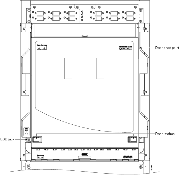
1.3 Front Door
The ONS15600SDH features a door to the front compartment that you can open by releasing the latches on the bottom left and right sides of the door. The front door provides access to the shelf, cable-management tray, and fans ( Figure1-2).
Figure 1-2 ONS 15600 SDH Front Door
You can remove the front door of the ONS15600SDH to provide unrestricted access to the front of the shelf. A label is pasted in a box in the center of the swing-down door that covers the fiber routers ( Figure1-3). This label designates the position of the rack and shelf in a lineup.
Figure 1-3 Bay Label
The front door also has a Class I laser warning ( Figure1-4).
Figure 1-4 Laser Warning Label
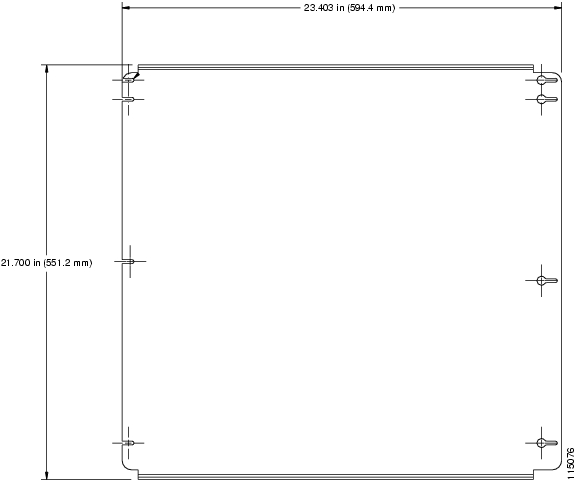
1.4 Rear Covers
The ONS15600SDH has an optional plastic rear cover that is held in place with six 6-32 x 3/8 inch Phillips screws. This plastic cover provides additional protection for the cables and connectors on the backplane ( Figure1-5).
Figure 1-5 Plastic Rear Cover
Figure1-6 shows the bus bar covers.
Figure 1-6 PDU Bus Bar Cover
1.5 Cable Routing
The narrow and wide cable routing modules (CRMs) can be installed on the sides of the bay to manage and contain the optical cables as they are routed away from the bay. You can use both types of fiber routing systems with overhead or under-floor cabling.
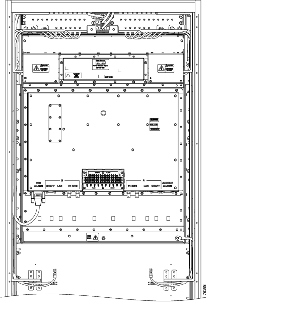
1.6 Customer Access Panel
The customer access panel (CAP) is located in the middle of the rear of the shelf. The CAP provides an alarm pin field, timing, and LAN connections. The CAP plugs into the backplane using 2-mm Hard Metric connectors with 752 pins and is held in place with one large captive bolt and multiple screws. Figure1-7 shows the location of the CAP on the back of the shelf.
Note
Figure 1-7 Rear of the ONS 15600 SDH, Including the CAP
The ONSONS15600SDH CAP provides the following:
•
•
•
•
•
•
The isolation and termination meet the intrabuilding lightning surge specified in Telcordia GR-1089 and ETS 300 386-1 and 60950. The CAP has -48VDC monitoring with I2C interface and nonvolatile memory to store the CAP revision information.
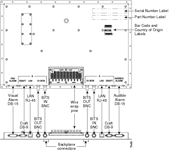
Figure1-8 shows the CAP faceplate.
Figure 1-8 CAP Faceplate and Connections
If the CAP fails, the node raises an EQPT alarm. You can replace the CAP on an in-service system without affecting traffic. To replace a CAP, refer to the CiscoONS15600SDH Troubleshooting Guide. Always replace the CAP during a maintenance window.
1.7 Alarm, Timing, LAN, and Craft Pin Connections
Caution
Warning
The ONS15600SDH has a backplane pin field located at the bottom rear of the shelf that is part of the CAP. The CAP provides 0.045 square inch (0.290 square centimeter) wire-wrap pins for enabling alarm inputs and outputs and timing input and output. This section describes the backplane pin field and pin assignments, as well as timing and LAN connections. See the "Customer Access Panel" section for more information.
1.7.1 External Alarm and Control Contact Installation
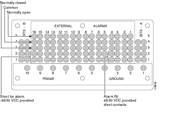
The external (environmental) alarm contacts consist of the wire-wrap pin field and two D-Sub 15s. The alarm pin field supports up to 16 alarm inputs (external alarms) and 16 alarm outputs (external controls). The two D-Sub 15s support four audible alarms, four visual alarms, one alarm cutoff (ACO), a PDU Fail A, and a PDU Fail B.
By connecting to different wire-wrap pins on the CAP, the alarm outputs can be configured for either NO or NC operation (see Figure1-9). The alarm inputs consist of two wire-wrap pins on the CAP and the alarm outputs consist of three wire-wrap pins.
1.7.1.1 Visual and Audible Alarms
Visual and audible alarm contacts are provisioned as Critical, Major, Minor, and Remote. Figure1-9 shows alarm pin assignments.
Figure 1-9 Alarm Pin Assignments on the CAP
Visual and audible alarms can be wired to trigger an alarm light at a central alarm collection point when the corresponding contacts are closed.
1.7.1.2 Alarm Cutoff (ACO) and PDU Alarms
The PDU Alarm connection controls the visual alarm indicators on the front of the PDU. You can also activate the alarm cutoff (ACO) function by pressing the ACO button on the TSC card faceplate. The ACO function extinguishes all audible alarm indications, but the alarm is still raised in Cisco Transport Controller (CTC).
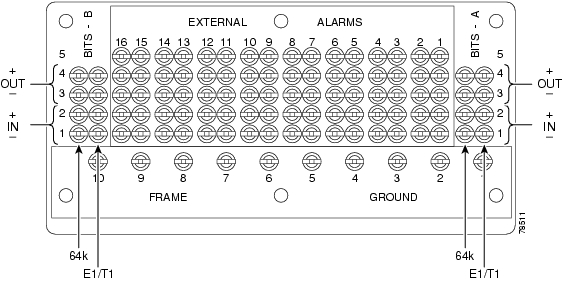
1.7.2 Timing Installation
The ONS15600SDH backplane supports two 100-ohm BITS clock pin fields. Figure1-10 shows the pin assignments for the BITS timing pin fields.
Note
Figure 1-10 BITS Timing Connections on the CAP
1.7.3 LAN Installation
Use a straight-through LAN cable with the LAN port on the ONS15600SDH CAP to connect the ONS15600SDH to a hub, switch, or a LAN modem for remote access to the node. Use a crossover cable when connecting the CAP to a workstation. You can also use a straight-through or crossover LAN cable with the LAN port on the active TSC faceplate to connect a workstation or to connect the ONS15600SDH to the network.
Note
1.7.4 TL1 Craft Interface Installation
To open a TL1 session using the craft interface on a PC, use the RJ-45 port on the active TSC card to access the system using a standard web browser. If a browser is not available, you can access the system using one of the two EIA/TIA-232 ports on the CAP. Each EIA/TIA-232 port supports VT100 emulation so that you can enter TL1 commands directly without using a web browser. Because the CAP EIA/TIA-232 port is set up as a data terminal equipment (DTE) interface, you must use a 3-pair swapping null modem adapter when you are working in a UNIX or PC environment so that the TXD/RXC, DSR/DTR, and CTS/RTS pins are swapped. Use a standard pin D-sub cable when connecting to a PC. Refer to the CiscoONS15600SDH TL1 Command Guide for more information.
Note
1.8 Power Distribution Unit
The power distribution unit (PDU) consists of a mounting chassis, A- and B-side power modules, an alarm module, and a rear input/output (I/O) unit. The ONS15600SDH PDU has LEDs that alert you to critical, major, minor, and remote alarms on the node. Each module can support three 100 A input power feeds, 48 VDC power load (based on a fully loaded ONS15600SDH shelf). The PDU supplies six 50 A power feeds to the shelves. (The PDU provided with the ONS15600SDH is capable of supplying power to up to three shelves.)
A three-shelf bay at the minimum operational voltage of -36 VDC requires 69 A per feed (207 A total). A three-shelf bay at the nominal operational voltage of -48 VDC requires 52 A per feed (156 A total). Each of the three feeds should be protected by its own 100 A breaker. A bus bar system, rather than wiring, provides a reliable, low resistance path to the ONS15600SDH shelf. Figure1-6 shows the PDU output covers found at the top rear of the bay.
1.9 Power and Ground Description
Warning
Ground the equipment according to Telcordia and ITU standards or local practices. The ground connection is located on the front of the bay's top horizontal rails. The ONS15600SDH provides two #12 tapped holes to accommodate the grounding lug. The lug must be a dual-hole type and rated for at least 125 A capacity. Figure1-11 shows the front and rear bay ground holes.
Figure 1-11 Front and Rear Bay Ground Holes
The main power connections are made at the PDU side terminals at the top of the bay. To install redundant power feeds, use four power cables and ground cables. For a single power feed, only two power cables and one ground cable (all rated for at least 125 A capacity) are required. Use a conductor with low impedance to ensure circuit overcurrent protection. The ground conductor must have the capability to safely conduct any faulty current that might be imposed.
Cisco recommends the following wiring conventions, but customer conventions prevail:
•
•
The ONS15600SDH shelf has redundant -48 VDC power terminals on its backplane. The terminals are labeled A FEEDS and B FEEDS and are located at the top left and right sides of the shelf behind clear plastic covers.
Refer to the Cisco ONS 15600 SDH Procedure Guide for installation procedures to install 600-mm and 900-mm kick plates when used with narrow cable routing modules (CRMs) and CRMs respectively.
Warning
Warning
1.10 Fan-Tray Assembly
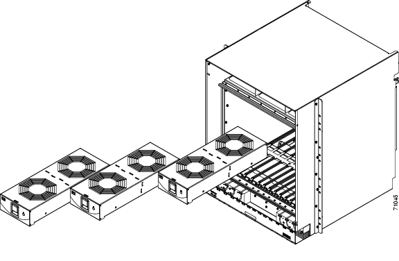
The fan-tray assembly is located at the top of the ONS15600SDH shelf front compartment. The fan-tray assembly has three removable drawers that hold two fans each and fan-control circuitry for the ONS15600SDH ( Figure1-12). You should only need to access the fans if a fan fails.
Figure 1-12 Fan-Tray Assembly
1.10.1 Air Filter
The ONS15600SDH contains a disposable air filter that is made of an open-cell polyurethane foam that is flame retardant and fungi resistant. The air filter is located above the three fan trays ( Figure1-13). This disposable filter is not designed to be cleaned. You can order air filter replacements from Cisco (Cisco P/N: 700-13116-xx). Replace this filter at least every 6 months and keep spare filters in stock. Refer to the Cisco ONS 15600 SDH Troubleshooting Guide for information about replacing the fan-tray air filter.
Warning
Caution
Figure 1-13 Air Filter with One Fan Tray Pulled Out
1.10.2 Fan Speed and Failure
If one or more fans fail on the fan-tray assembly, replace the fan tray where that fan resides. You cannot replace individual fans. The red FAN LED on the front of the fan tray turns on when one or more fans fail. For fan-tray replacement instructions, refer to the CiscoONS15600SDH Troubleshooting Guide. The red FAN LED clears after you install a working fan tray.
Caution
Caution
Note
Fan speed is determined by card temperature sensors that report temperature data to the active TSC card. The sensors measure the input and output air temperature for each card. Fan speed options are low, medium, and high. For example, if a card exceeds permissible operational temperature, the fan speed increases appropriately. At initial turn-up, the default fan speed is high until the node initializes. If both TSC cards fail, the fans automatically shift to high speed. If a single TSC fails, the active TSC still controls the fan speed. Table1-1 shows the power requirements for an individual fan in a fan tray.
1.11 Cards and Slots
When a card is inserted in a card slot it will contact the shelf backplane but is not fully installed until the ejectors are fully closed.
1.11.1 Card Slot Requirements
The ONS15600SDH shelf has 14 card slots numbered sequentially from left to right. Slots 1 to 4 and 11 to 14 are reserved for optical (STM-N) traffic cards. These slots can host any of the ONS15600SDH optical cards. Slots 6/7 and 8/9 are dedicated to CXC cards, and Slots 5 and 10 house the TSC cards. Each card is keyed to fit only in an appropriate slot for that card. Unused card slots should be occupied by a filler card (blank faceplate).
Warning
Caution
Shelf assembly slots have symbols indicating the type of cards that you can install in them. Each ONSONS15600SDH card has a corresponding symbol. The symbol on the card must match the symbol on the slot.
Table1-2 shows the slot and card symbol definitions.
See Chapter2, "Cards Features and Functions," for more information about ONS15600SDH cards.
All physical connections to the optical cards are made through OGI (Optical Gateway Interface) connectors on the card faceplate. Table1-3 lists the number of ports and the line rates for ONS15600SDH optical cards.
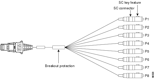
1.11.2 OGI Cables
The ONS15600SDH faceplate has OGI connectors that terminate in either SC, ST, or FC connectors. Figure1-14 shows the OGI to SC cable breakout for the STM-16 card.
Figure 1-14 OGI Cable Breakout
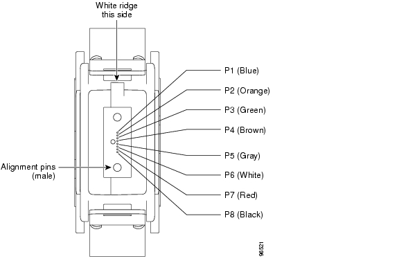
Figure1-15 show the OGI pin breakout for the STM-16 card.
Figure 1-15 OGI Pin Breakout
1.11.3 Optical Card Cable Routing
The ONS15600SDH has a cable-management tray with discrete fiber routing paths for each optical card's cables. Each fiber routing path has a plastic cable latch for securing the cables in the fiber routing path. You can rotate the cable latch into two positions, open or closed; make sure that the cable latch is always completely open before you insert or remove the optical cables. Make sure all fiber-optic cables are disconnected from a card before you remove it.
1.11.4 Card Replacement
To replace an ONS15600SDH card with another card of the same type, you do not need to make any changes to the database; remove the old card and replace it with a new card. You can use the CTC ChangeCard feature to replace a card with a new card while maintaining all existing provisioning. To replace a card with a card of a different type, delete the original card from CTC, physically remove the card, and replace it with the new card.
Caution
Note
Warning
![]()
![]()
![]()
![]()
![]()
![]()
![]()
![]()
Posted: Fri Feb 27 18:31:56 PST 2004
All contents are Copyright © 1992--2004 Cisco Systems, Inc. All rights reserved.
Important Notices and Privacy Statement.