cc/td/doc/product/ong/600_sdh/sdh60014
hometocprevnextglossaryfeedbacksearchhelp
PDF

Table Of Contents

Cards Features and Functions

Common Control Cards

Timing and Shelf Controller Card

Core Cross Connect Card

Optical Traffic Cards

OC48/STM16 LR/LH 16 Port 1550 Card

OC48/STM16 SR/SH 16 Port 1310 Card

OC192/STM64 LR/LH 4 Port 1550 Card

OC192/STM64 SR/SH 4 Port 1310 Card

Filler Card

Cards Features and Functions


This chapter describes Cisco ONS15600SDH card features and functions.

Chapter topics include:

Common Control Cards

Optical Traffic Cards

Filler Card

2.1  Common Control Cards

Follow all warnings listed on the equipment or in the documentation.


Warning Voltage is present on the backplane when the system is operating. To reduce risk of an electric shock, keep hands and fingers out of the power supply bays and backplane areas.


Caution When working with cards, wear the supplied ESD wristband to avoid ESD damage to the card. Plug the wristband cable into the ESD jack located on the lower-left outside edge of the shelf assembly.


Caution Do not operate the ONS15600SDH with a single TSC card or a single CXC card installed. Always operate the shelf with one active card and one protect card.


2.1.1  Timing and Shelf Controller Card

The Timing and Shelf Controller (TSC) card performs all system timing functions for each ONS15600SDH. The TSC card monitors the recovered clocks from each traffic card and two building integrated timing supply (BITS) interfaces for frequency accuracy. The TSC card is provisionable, allowing timing from any optical interface source, a BITS input source, or internal clock source as the system-timing reference. You can provision any of the clock inputs as primary or secondary timing sources, but the ONS15600SDH does not support mixed timing references. If you specify external timing references, your options are BITS1, BITS2, and the internal clock sources. If you select line timing, you can specify up to two line ports from which to derive timing, as well as the internal clock sources. You cannot specify BITS as the primary reference and a line source as the secondary reference. A slow-reference tracking loop allows the TSC to synchronize with the recovered clock and enables holdover if the reference is lost.

The TSC card also provides shelf control related functions. The TSC card has a 100-Mbps Ethernet link to each card on the shelf and monitors the presence of these cards. The TSC provides bulk memory for nonvolatile storage of system software and data and provides EIA/TIA-232 and Ethernet customer interfaces. The TSC card processes and routes line and section data communications channel (DCC) traffic as well as routing the K1, K2, and K3 overhead bytes between traffic (line) cards and Core Cross Connect (CXC) cards. The TSC card controls and monitors the shelf fans and all of the alarm interfaces.

2.1.1.1  TSC Slots and Connectors

Install TSC cards in Slots 5 and 10 for redundancy. If the active TSC card fails, timing reference and control function switches to the protect TSC card. All TSC card protection switches conform to the Telcordia protection switching standard of equal to or less than 50ms.

The TSC card features an RJ-45 10/100BaseT LAN port on the faceplate. Two additional RJ-45 10/100BaseT LAN ports and two EIA/TIA-232 DB-9 type craft user interfaces are available via the customer access panel (CAP) on the backplane.

2.1.1.2  TSC Faceplate and Block Diagram

Figure2-1 shows the TSC card faceplate and a block diagram of the card.

Figure 2-1 TSC Card Faceplate and Block Diagram

2.1.1.3  TSC Card-Level Indicators

Table2-1 describes the functions of the card-level LEDs on the TSC card faceplate.

Table 2-1 TSC Card-Level Indicators 

Indicator LED
Color
Definition
STAT

Red

Indicates a hardware fault; this LED is off during normal operation. Replace the card if the STAT LED persists. During diagnostics, the LED will flash quickly during initialization and slowly during configuration synchronization.

SRV

Green

The service mode of the card; green indicates that the card is in use and off indicates that the card can be removed for service.

ACT/STBY

Green

The ACT/STBY (Active/Standby) LED indicates that the TSC is active (green) or standby (off).


2.1.1.4  TSC Network-Level Indicators

Table2-2 describes the functions of the network-level LEDs on the TSC card faceplate.

.

Table 2-2 TSC Network-Level Indicators 

Indicator LED
Color
Definition
LINE

Green

Node timing is synchronized to a line timing reference.

EXTERNAL

Green

Node timing is synchronized to an external timing reference.

FREE RUN

Green

Node is not using an external timing reference. Indicated when the timing mode is set to an internal reference or after all external references are lost.

HOLDOVER

Amber

External/line timing references have failed. The TSC has switched to internal timing and the 24-hour holdover period has not elapsed.

ACO

Amber

The alarm cutoff (ACO) push button has been activated. After pressing the ACO button, the amber ACO LED turns on. The ACO button opens the audible closure on the backplane. The ACO state is stopped if a new alarm occurs. After the originating alarm is cleared, the ACO LED and audible alarm control are reset.


2.1.1.5  TSC Push-Button Switches

Table2-3 describes the functions of the push-button switches on the TSC card faceplate.

Table 2-3 TSC Card Push-Button Switches 

Push-Button
Function
ACO

Extinguishes external audible (environmental) alarms. When this button is activated, the amber-colored ACO LED turns on.

LAMP TEST

Verifies that all the LEDs in the shelf are functioning properly. When this button is activated, all of the front-panel LEDs in the shelf turn on temporarily to verify operation.

RESET

Activates a soft reset of all of the main processor memory on the card.

Note The RESET button is recessed to prevent accidental activation.


2.1.1.6  TSC Card Specifications

Table2-4 shows the TSC card specifications.

Table 2-4 TSC Card Specifications 

Specification Type
Description
CTC Software

Interface: 10/100BaseT LAN

Backplane (CAP) access: RJ-45

TL1 Craft Interface

Speed: 10/100BaseT LAN

Front panel access: RJ-45 type connector

Backplane access: RJ-45 and EIA/TIA-232 DB-9 type connector

Synchronization

Free running access: Accuracy 4.6 ppm

Holdover stability: 3.7 x10⁻⁷ ppm/day including temperature (< 255 slips in first 24 hours)

Reference: External BITS, line, internal

Operating Temperature

23 to 122 degrees Fahrenheit (-5 to +50 degrees Celsius)

Operating Humidity

5 to 95 percent, noncondensing

Dimensions

Height: 16.50 in. (419 mm)

Width: 1.07 in. (27 mm)

Depth: 18.31 in. (465 mm)

Card weight: 4.0 lb (1.81 kg)

Compliance

When installed in a system, ONS15600SDH cards comply with these safety standards: UL 60950, CSA C22.2 No. 950, EN 60950, IEC 60950


2.1.2  Core Cross Connect Card

The Core Cross Connect card (CXC) is the central element for ONS15600SDH switching. The CXC card establishes connections and performs time division switching (TDS) at VC-4 and VC4-Nc levels between ONS15600SDH traffic cards.

The CXC card works with the TSC card to maintain connections and set up cross-connects within the ONS15600SDH. You establish cross-connect and provisioning information using TL1 or Cisco Transport Controller (CTC). The TSC card stores the proper internal cross-connect information and relays the setup information to the CXC card.

2.1.2.1  CXC Switch Matrix

The switch matrix on each CXC card consists of 2,048 VC4 ports. When creating bidirectional VC4 cross-connects, each cross-connect uses two VC4 ports. This results in 1,024 bidirectional VC4 cross-connects. Any VC4 on any port can be connected to any other port, meaning that the VC4 cross-connections are non blocking. Nonblocking connections allow network operators to connect any VC4, VC4-4c, VC4-8c, VC4-16c, or VC4-64c payload that is received on an STM-16 or STM-64 interface to any other interface capable of supporting the bandwidth.

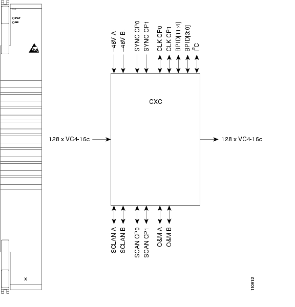
The CXC card has 128 input ports and 128 output ports capable of VC4-16. A VC4 on any of the input ports can be mapped to a VC4 output port, thus providing full VC4 time slot assignments (TSA).

2.1.2.2  CXC Slots and Connectors

Install a CXC card in Slot 6 and a second CXC card in Slot 8 for redundancy. (Slots 7 and 9 are also occupied by the CXC faceplate.) The CXC card has no external interfaces. All CXC card interfaces are provided on the ONS15600SDH backplane.

2.1.2.3  CXC Faceplate and Block Diagram

Figure2-2 shows the CXC card faceplate and a block diagram of the card.

Figure 2-2 CXC Card Faceplate and Block Diagram

2.1.2.4  CXC Card-Level Indicators

Table2-5 describes the functions of the card-level LEDs on the CXC card faceplate.

Table 2-5 CXC Card-Level Indicators  

Indicators LED
Color
Definition
STAT

Red

Indicates a hardware fault; this LED is off during normal operation. Replace the card if the STAT LED persists. During diagnostics, the LED will flash quickly during initialization and flash slowly during configuration synchronization.

SRV

Green

The service mode of the card. Green indicates the card is in use; off indicates that the card can be removed for service.


2.1.2.5  CXC Specifications

Table2-6 shows the CXC card specifications.

Table 2-6 CXC Card Specifications 

Specification Type
Description
Cross-Connect

Connection setup time: 7microseconds

Latency: 0.5microseconds

Operating Temperature

23 to 122 degrees Fahrenheit (-5 to +50 degrees Celsius)

Operating Humidity

5 to 95 percent, noncondensing

Dimensions

Height: 16.50 in. (419 mm)

Width: 2.40 in. (61 mm)

Depth: 18.31 in. (465 mm)

Card weight: 5.0 lb (2.27 kg)

Compliance

When installed in a system, ONS15600SDH cards comply with these safety standards: UL 60950, CSA C22.2 No. 950, EN 60950, IEC 60950


2.2  Optical Traffic Cards


Warning Voltage is present on the backplane when the system is operating. To reduce risk of an electric shock, keep hands and fingers out of the power supply bays and backplane areas.


Warning Invisible laser radiation may be emitted from the end of the unterminated fiber cable or connector. Do not stare into the beam or view directly with optical instruments. Viewing the laser output with certain optical instruments (for example, eye loupes, magnifiers, and microscopes) within a distance of 100 mm may pose an eye hazard. Use of controls or adjustments or performance of procedures other than those specified may result in hazardous radiation exposure.


2.2.1  OC48/STM16 LR/LH 16 Port 1550 Card

The OC48/STM16LR/LH 16Port1550 card provides 16 long-haul STM-16 ITU-T G.957 L-16.2 compliant signals. The ports operate at the ITU-T G.707 compliant 2488.320 Mbps rate over a single-mode fiber span. The OC48/STM16LR/LH 16Port1550 card has four physical connector adapters with eight fibers per connector adapter. The card supports VC4 payloads and concatenated payloads at VC4, VC4-4c, VC4-8c, or VC4-16c signal levels.

2.2.1.1  OC48/STM16 LR/LH 16 Port 1550 Slots and Connectors

You can install OC48/STM16LR/LH 16Port1550 cards in Slots 1 through 4 and 11 through 14. The card provides four bidirectional OGI (Optical Gateway Interface) type connector adapters on the faceplate (angled downward), each carrying eight fiber strands (four transmit and four receive).

2.2.1.2  OC48/STM16 LR/LH 16 Port 1550 Faceplate and Block Diagram

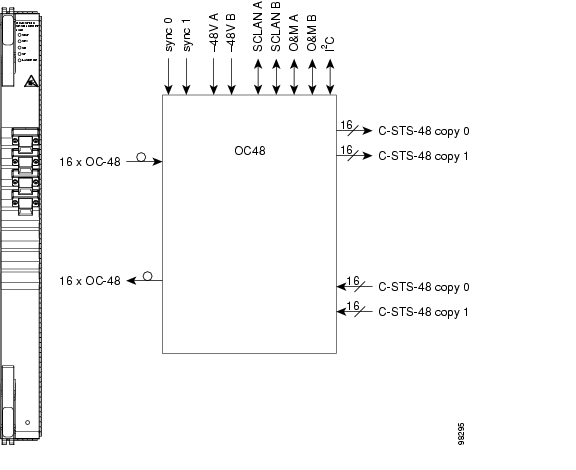
Figure2-3 shows the OC48/STM16LR/LH 16Port1550 faceplate and a block diagram of the card.

Figure 2-3 OC48/STM16 LR/LH 16 Port 1550 Faceplate and Block Diagram

2.2.1.3  OC48/STM16 LR/LH 16 Port 1550 Card-Level Indicators

Table2-7 describes the functions of the card-level LEDs on the OC48/STM16LR/LH 16Port1550 card.

Table 2-7 OC48/STM16 LR/LH 16 Port 1550 Card-Level Indicators  

Indicators
Color
Description
STAT LED

Red

Indicates a hardware fault; this LED is off during normal operation. Replace the card if the STAT LED persists. During diagnostics, the LED will flash quickly during initialization and flash slowly during configuration synchronization.

SRV LED

Green

The service mode of the card; green indicates that the card is in use and off indicates that the card can be removed for service.

LASER ON

Green

The green LASER ON LED indicates that at least one of the card's lasers is active.


2.2.1.4  OC48/STM16 LR/LH 16 Port 1550 Network-Level Indicators

Table2-8 describes the functions of the network-level LEDs on the OC48/STM16LR/LH 16Port1550 card.

Table 2-8 OC48/STM16 LR/LH 16 Port 1550 Network-Level Indicators  

Indicators
Color
Description
SD LED

Blue

The blue SD LED indicates a signal degrade or condition such as a low level signal on at least one of the card's ports.

SF LED

Red

The red SF LED indicates a signal failure or condition such as loss of signal (LOS) or loss of frame alignment, or turns on when the transmit and receive fibers are incorrectly connected. When the fibers are properly connected, the LED turns off.


Warning Invisible laser radiation may be emitted from the end of the unterminated fiber cable or connector. Do not stare into the beam or view directly with optical instruments. Viewing the laser output with certain optical instruments (for example, eye loupes, magnifiers, and microscopes) within a distance of 100 mm may pose an eye hazard. Use of controls or adjustments or performance of procedures other than those specified may result in hazardous radiation exposure.


2.2.1.5  OC48/STM16 LR/LH 16 Port 1550 Specifications

Table2-9 shows the OC48/STM16LR/LH 16Port1550 card specifications.

Table 2-9 OC48/STM16 LR/LH 16 Port 1550 Card Specifications 

Specification Type
Description
Line

Bit rate: 2.49 Gbps

Code: Scrambled NRZ

Fiber: 1550-nm single mode

Loopback mode: Facility

Connectors: OGI

Compliance: Telcordia GR-253-CORE, ITU-T G.707, ITU-T G.957

Transmitter

Max. Transmitter output power: +3 dBm

Min. Transmitter output power: -2 dBm

Center wavelength: 1500 nm to 1580 nm

Nominal wavelength: 1550 nm

Transmitter: Distributed feedback (DFB) laser

Note The CTC Maintenance > Transceiver tab shows the optical power transmitted (OPT) levels. CTC might show OPT levels at 1 dBm more or less than the actual card OPT level.

Receiver

Max. receiver level: -9 dBm

Min. receiver level: -28 dBm

Receiver: InGaAs APD photodetector

Link Loss Budget: 26 dB minimum, with 1 dBm dispersion penalty

Loopback Mode

Facility (Line)

Note You must use a 19 to 24 dBm (15 to 20 dBm is recommended) fiber attenuator when connecting a fiber loopback to an OC48/STM16 LR/LH 16 Port 1550 card. Never connect a direct fiber loopback.

Operating Temperature

23 to 122 degrees Fahrenheit (-5 to +50 degrees Celsius)

Operating Humidity

5 to 95 percent, noncondensing

Dimensions

Height: 16.50 in. (419 mm)

Width: 1.07 in. (27 mm)

Depth: 18.31 in. (465 mm)

Card weight: 5.0 lb (2.27 kg)

Compliance

Telcordia GR-253, ITU-T G.707, ITU-T G.957

When installed in a system, ONS15600SDH cards comply with these safety standards: UL 60950, CSA C22.2 No. 950, EN 60950, IEC 60950

Eye safety compliance: Class 1 (21 CFR 1040.10 and 1040.11) and Class1 (IEC 60825) laser products


2.2.1.6  OC48/STM16 LR/LH 16 Port 1550 Card OGI Connector Pinout

Table2-10 shows the OC48/STM16LR/LH 16Port1550 card OGI connector pinouts.

Table 2-10 OC48/STM16 LR/LH 16 Port 1550 Card OGI Connector Pinout

Connector
OGI Pin and Card Port

1

1

2

3

4

5

6

7

8

Transmit 4

Receive 4

Transmit 3

Receive 3

Transmit 2

Receive 2

Transmit 1

Receive 1

2

1

2

3

4

5

6

7

8

Transmit 8

Receive 8

Transmit 7

Receive 7

Transmit 6

Receive 6

Transmit 5

Receive 5

3

1

2

3

4

5

6

7

8

Transmit 12

Receive 12

Transmit 11

Receive 11

Transmit 10

Receive 10

Transmit 9

Receive 9

4

1

2

3

4

5

6

7

8

Transmit 16

Receive 16

Transmit 15

Receive 15

Transmit 14

Receive 14

Transmit 13

Receive 13


2.2.2  OC48/STM16 SR/SH 16 Port 1310 Card

The OC48/STM16SR/SH 16Port1310 card provides 16 short-haul STM-16 ITU-T G.957 I-16 compliant signals. The ports operate at the ITU-T G.707 compliant 2488.320-Mbps rate over a single-mode fiber span. The OC48/STM16SR/SH 16Port1310 card has four physical connector adapters with eight fibers per connector adapter. The card supports VC4 payloads and concatenated payloads at VC4, VC4-4c, VC4-8c, or VC4-16c signal levels.

2.2.2.1  OC48/STM16 SR/SH 16 Port 1310 Slots and Connectors

You can install OC48/STM16SR/SH 16Port1310 cards in Slots 1 through 4 and 11 through 14. The card provides four bidirectional OGI type connector adapters on the faceplate (angled downward), each carrying eight fiber strands (four transmit and four receive).

2.2.2.2  OC48/STM16 SR/SH 16 Port 1310 Faceplate and Block Diagram

Figure2-4 shows the OC48/STM16SR/SH 16Port1310 faceplate.

Figure 2-4 OC48/STM16 SR/SH 16 Port 1310 Faceplate

2.2.2.3  OC48/STM16 SR/SH 16 Port 1310 Card-Level Indicators

Table2-11 describes the functions of the card-level LEDs on the OC48/STM16SR/SH 16Port1310 card.

Table 2-11 OC48/STM16 SR/SH 16 Port 1310 Card-Level Indicators  

Indicators
Color
Description
STAT LED

Red

Indicates a hardware fault; this LED is off during normal operation. Replace the card if the STAT LED persists. During diagnostics, the LED will flash quickly during initialization and flash slowly during configuration synchronization.

SRV LED

Green

The service mode of the card. Green indicates the card is in use; off indicates that the card can be removed for service.

LASER ON

Green

The green LASER ON LED indicates that at least one of the card's lasers is active.


2.2.2.4  OC48/STM16 SR/SH 16 Port 1310 Network-Level Indicators

Table2-12 describes the functions of the network-level LEDs on the OC48/STM16SR/SH 16Port1310 card.

Table 2-12 OC48/STM16 SR/SH 16 Port 1310 Network-Level Indicators  

Indicators
Color
Description
SD LED

Blue

The blue SD LED indicates a signal degrade or condition such as a low level signal on at least one of the card's ports.

SF LED

Red

The red SF LED indicates a signal failure or condition such as LOS, LOF, or high bit error rate (BER) on at least one of the card's ports. The red SF LED also turns on when the transmit and receive fibers are incorrectly connected. When the fibers are properly connected, the LED turns off.


Warning Invisible laser radiation may be emitted from the end of the unterminated fiber cable or connector. Do not stare into the beam or view directly with optical instruments. Viewing the laser output with certain optical instruments (for example, eye loupes, magnifiers, and microscopes) within a distance of 100 mm may pose an eye hazard. Use of controls or adjustments or performance of procedures other than those specified may result in hazardous radiation exposure.


2.2.2.5  OC48/STM16 SR/SH 16 Port 1310 Specifications

Table2-13 shows the OC48/STM16SR/SH 16Port1310 card specifications.

Table 2-13 OC48/STM16 SR/SH 16 Port 1310 Card Specifications 

Specification Type
Description
Line

Bit rate: 2.49 Gbps

Code: Scrambled NRZ

Fiber: 1310-nm single mode

Loopback mode: Facility

Connectors: OGI

Compliance: Telcordia GR-253, ITU-T G.707, ITU-T G.957

Transmitter

Max. Transmitter output power: -3 dBm

Min. Transmitter output power: -10 dBm

Center wavelength: 1266 nm to 1360 nm

Nominal wavelength: 1310 nm

Transmitter: Fabry Perot laser

Note The CTC Maintenance > Transceiver tab shows the OPT levels. CTC might show OPT levels at 1 dBm more or less than the actual card OPT level.

Receiver

Max. receiver level: -3 dBm

Min. receiver level: -18 dBm

Receiver: PIN diode

Link Loss Budget: 8 dBm min., with 1 dBm dispersion penalty

Loopback Mode

Facility (Line)

Note You must use a 3-dBm fiber attenuator when connecting a fiber loopback to an OC48/STM16 SR/SH 16 port 1310 card. Never connect a direct fiber loopback.

Operating Temperature

23 to 122 degrees Fahrenheit (-5 to +50 degrees Celsius)

Operating Humidity

5 to 95 percent, noncondensing

Dimensions

Height: 16.50 in. (419 mm)

Width: 1.07 in. (27 mm)

Depth: 18.31 in. (465 mm)

Card weight: 5.0 lb (2.27 kg)

Compliance

Telcordia GR-253, ITU-T G.707, ITU-T G.957

When installed in a system, ONS15600SDH cards comply with these safety standards: UL 60950, CSA C22.2 No. 950, EN 60950, IEC 60950

Eye safety compliance: Class 1 (21 CFR 1040.10 and 1040.11) and Class1 (IEC 60825) laser products


2.2.2.6  OC48/STM16 SR/SH 16 Port 1310 Card OGI Connector Pinout

Table2-14 shows the OC48/STM16 SR/SH 16 Port 1310 card OGI connector pinouts.

Table 2-14 OC48/STM16 SR/SH 16 Port 1310 Card OGI Connector Pinout

Connector
OGI Pin and Card Port

1

1

2

3

4

5

6

7

8

Transmit 4

Receive 4

Transmit 3

Receive 3

Transmit 2

Receive 2

Transmit 1

Receive 1

2

1

2

3

4

5

6

7

8

Transmit 8

Receive 8

Transmit 7

Receive 7

Transmit 6

Receive 6

Transmit 5

Receive 5

3

1

2

3

4

5

6

7

8

Transmit 12

Receive 12

Transmit 11

Receive 11

Transmit 10

Receive 10

Transmit 9

Receive 9

4

1

2

3

4

5

6

7

8

Transmit 16

Receive 16

Transmit 15

Receive 15

Transmit 14

Receive 14

Transmit 13

Receive 13


2.2.3  OC192/STM64 LR/LH 4 Port 1550 Card

The OC192/STM64LR/LH 4port1550 card provides four long-haul STM-64 ITU-T G.691 L-64.2c (shifted by 4-5 dB) compliant signals. The ports operate at the ITU-T G.707 compliant 9953.28-Mbps rate over a single-mode fiber span. The OC192/STM64LR/LH 4port1550 card has four physical connector adapters with two fibers per connector adapter. The card supports VC4 payloads and concatenated payloads at VC4, VC4-4c, VC4-8c, VC4-16c, or VC4-64c signal levels.

2.2.3.1  OC192/STM64 LR/LH 4 Port 1550 Slots and Connectors

You can install OC192/STM64LR/LH 4port1550 cards in Slots 1 through 4 and 11 through 14. The card provides four bidirectional OGI type connector adapters on the faceplate (angled downward), carrying two fiber strands (1 transmit and 1 receive). Only one transmit and receive pair is used per connector adapter. On a breakout cable, use Port 3, Fiber 4 (transmit), and Fiber 3 (receive).

2.2.3.2  OC192/STM64 LR/LH 4 Port 1550 Faceplate and Block Diagram

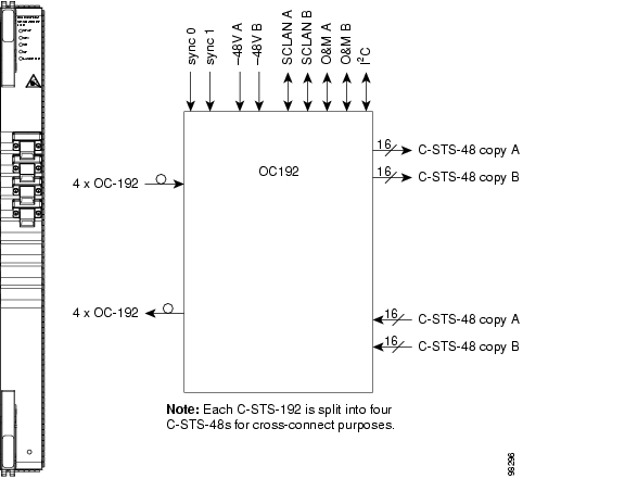
Figure2-5 shows the OC192/STM64LR/LH 4Port1550 faceplate and a block diagram of the card.

Figure 2-5 OC192/STM64 LR/LH 4 Port 1550 Faceplate and Block Diagram

2.2.3.3  OC192/STM64 LR/LH 4 Port 1550 Card-Level Indicators

Table2-15 describes the functions of the card-level LEDs on the OC192/STM64LR/LH 4Port1550 card.

Table 2-15 OC192/STM64 LR/LH 4 Port 1550 Card-Level Indicators  

Indicators
Color
Description
STAT LED

Red

Indicates a hardware fault; this LED is off during normal operation. Replace the unit if the STAT LED persists. During diagnostics, the LED will flash quickly during initialization and flash slowly during configuration synchronization.

SRV LED

Green

The service mode of the card. Green indicates the card is in use; off indicates that the card can be removed for service.

LASER ON

Green

The green LASER ON LED indicates that at least one of the card's lasers is active.


2.2.3.4  OC192/STM64 LR/LH 4 Port 1550 Network-Level Indicators

Table2-16 describes the functions of the network-level LEDs on the OC192/STM64LR/LH 4Port1550 card.

Table 2-16 OC192/STM64 LR/LH 4 Port 1550 Network-Level Indicators  

Indicators
Color
Description
SD LED

Blue

The blue SD LED indicates a signal degrade or condition such as a low signal level on at least one of the card's ports.

SF LED

Red

The red SF LED indicates a signal failure or condition such as LOS, LOF, or high BERs on at least one of the card's ports. The red SF LED is also on when the transmit and receive fibers are incorrectly connected. When the fibers are properly connected, the LED turns off.


Warning Invisible laser radiation may be emitted from the end of the unterminated fiber cable or connector. Do not stare into the beam or view directly with optical instruments. Viewing the laser output with certain optical instruments (for example, eye loupes, magnifiers, and microscopes) within a distance of 100 mm may pose an eye hazard. Use of controls or adjustments or performance of procedures other than those specified may result in hazardous radiation exposure.


2.2.3.5  OC192/STM64 LR/LH 4 Port 1550 Specifications

Table2-17 shows the OC192/STM64LR/LH 4Port1550 card specifications.

Table 2-17 OC192/STM64 LR/LH 4 Port 1550 Card Specifications 

Specification Type
Description
Line

Bit rate: 9.96 Gbps

Code: Scrambled NRZ

Fiber: 1550-nm single mode

Transmitter

Max. transmitter output power: +7dBm

Min. transmitter output power: +4dBm

Center wavelength: 1530nm to 1565nm

Nominal wavelength: 1550nm

Transmitter: LN (Lithium Niobate) external modulator transmitter

Receiver

Max. receiver level: -9dBm

Min. receiver level: -22dBm

Receiver: APD/TIA (Avalanche Photo Diode/Trans Impedance Amplifier)

Link loss budget: 24dB min., with no dispersion or 22dB optical path loss at BER = 1- exp (-12) including dispersion

Loopback Mode

Payload

Note You must use a 19 to 24 dB (15 to 20 is recommended) fiber attenuator when connecting a fiber loopback to an OC192/STM64 LR/LH 4 Port 1550 card. Never connect a direct fiber loopback.

Connectors

OGI

Operating Temperature

23 to 122 degrees Fahrenheit (-5 to +50 degrees Celsius)

Operating Humidity

5 to 95 percent, noncondensing

Dimensions

Height: 16.50in. (419mm)

Width: 1.07in. (27mm)

Depth: 18.31in. (465mm)

Card weight: 12.0lb (5.44kg)

Compliance

Telcordia GR-253, ITU-T G.707, ITU-T G.691

When installed in a system, ONS15600SDH cards comply with these safety standards: UL 60950, CSA C22.2 No. 950, EN 60950, IEC 60950

Eye safety compliance: Class 1 (21 CFR 1040.10 and 1040.11) and Class1 (IEC 60825) laser products


2.2.3.6  OC192/STM64 LR/LH 4 Port 1550 Card OGI Connector Pinout

Table2-18 shows the OC192/STM64LR/LH 4Port1550 card OGI connector pinouts.

Table 2-18 OC192/STM64 LR/LH 4 Port 1550 Card OGI Connector Pinout

Connector
OGI Pin and Card Port

1

1

2

3

4

5

6

7

8

Transmit 1

Receive 1

2

1

2

3

4

5

6

7

8

Transmit 2

Receive 2

3

1

2

3

4

5

6

7

8

Transmit 3

Receive 3

4

1

2

3

4

5

6

7

8

Transmit 4

Receive 4


2.2.4  OC192/STM64 SR/SH 4 Port 1310 Card

The OC192/STM64SR/SH 4Port1310 card provides four short-haul STM-64 ITU-T G.691 I-64.1r compliant signals. The ports operate at ITU-T G.707 compliant 9953.28-Mbps rate over a single-mode fiber span. The OC192/STM64SR/SH 4port1310 card has four physical connector adapters with two fibers per connector adapter. The card supports STS-1 payloads and concatenated payloads at VC4, VC4-4c, VC4-8c, VC4-16c, or VC4-64c signal levels.

2.2.4.1  OC192/STM64 SR/SH 4 Port 1310 Slots and Connectors

You can install OC192/STM64SR/SH 4Port1310 cards in Slots 1 through 4 and 11 through 14. The card provides four bidirectional OGI type connector adapters on the faceplate (angled downward), carrying two fiber strands (one transmit and one receive). Only one transmit and receive pair is used per connector adapter. On a breakout cable, use Port 3, Fiber 4 (transmit) and Fiber 3 (receive).

2.2.4.2  OC192/STM64 SR/SH 4 Port 1310 Faceplate and Block Diagram

Figure2-6 shows the OC192/STM64SR/SH 4Port1310 faceplate.

Figure 2-6 OC192/STM64 SR/SH 4 Port 1310 Faceplate

2.2.4.3  OC192/STM64 SR/SH 4 Port 1310 Card-Level Indicators

Table2-19 describes the functions of the card-level LEDs on the OC192/STM64SR/SH 4Port1310 card.

Table 2-19 OC192/STM64 SR/SH 4 Port 1310 Card-Level Indicators  

Indicators
Color
Description
STAT LED

Red

Indicates a hardware fault; this LED is off during normal operation. Replace the unit if the STAT LED persists. During diagnostics, the LED will flash quickly during initialization and flash slowly during configuration synchronization.

SRV LED

Green

The service mode of the card. Green indicates the card is in use; off indicates that the card can be removed for service.

LASER ON

Green

The green LASER ON LED indicates that at least one of the card's lasers is active.


2.2.4.4  OC192/STM64 SR/SH 4 Port 1310 Network-Level Indicators

Table2-20 describes the functions of the network-level LEDs on the OC192/STM64SR/SH 4Port1310 card.

Table 2-20 OC192/STM64 SR/SH 4 port 1310 Network-Level Indicators  

Indicators
Color
Description
SD LED

Blue

The blue SD LED indicates a signal degrade or condition such as a low signal level on at least one of the card's ports.

SF LED

Red

The red SF LED indicates a signal failure or condition such as LOS, LOF, or high BER on at least one of the card's ports. The red SF LED also turns on when the transmit and receive fibers are incorrectly connected. When the fibers are properly connected, the LED turns off.


Warning Invisible laser radiation may be emitted from the end of the unterminated fiber cable or connector. Do not stare into the beam or view directly with optical instruments. Viewing the laser output with certain optical instruments (for example, eye loupes, magnifiers, and microscopes) within a distance of 100 mm may pose an eye hazard. Use of controls or adjustments or performance of procedures other than those specified may result in hazardous radiation exposure.


2.2.4.5  OC192/STM64 SR/SH 4 Port 1310 Specifications

Table2-21 shows the OC192/STM64SR/SH 4Port1310 card specifications.

Table 2-21 OC192/STM64 SR/SH 4 Port 1310 Card Specifications 

Specification Type
Description
Line

Bit rate: 9.96 Gbps

Code: Scrambled nonreturn to zero (NRZ)

Fiber: 1310-nm single mode

Transmitter

Max. transmitter output power: -1dBm

Min. transmitter output power: -6dBm

Center wavelength: 1290nm to 1330nm

Nominal wavelength: 1310nm

Receiver

Max. receiver level: -1dBm

Min. receiver level: -11dBm

Link loss budget: 5dB min., with no dispersion or 4dB optical path loss at BER = 1- exp (-12) including dispersion

Loopback Mode

Payload

Note You must use a 3-dBm fiber attenuator when connecting a fiber loopback to an OC192/STM64 SR/SH 4 Port 1310 card. Never connect a direct fiber loopback.

Connectors

OGI

Operating Temperature

23 to 122 degrees Fahrenheit (-5 to +50 degrees Celsius)

Operating Humidity

5 to 95 percent, noncondensing

Dimensions

Height: 16.50in. (419mm)

Width: 1.07in. (27mm)

Depth: 18.31in. (465mm)

Card weight: 12.0lb (5.44kg)

Compliance

Telcordia GR-253, ITU-T G.707, ITU-T G.691

When installed in a system, ONS15600SDH cards comply with these safety standards: UL 60950, CSA C22.2 No. 950, EN 60950, IEC 60950

Eye safety compliance: Class 1 (21 CFR 1040.10 and 1040.11) and Class1 (IEC 60825) laser products


2.2.4.6  OC192/STM64 SR/SH 4 Port 1310 Card OGI Connector Pinout

Table2-22 shows the OC192/STM64SR/SH 4Port1310 card OGI connector pinouts.

Table 2-22 OC192/STM64 SR/SH 4 Port 1310 Card OGI Connector Pinout

Connector
OGI Pin and Card Port

1

1

2

3

4

5

6

7

8

Transmit 1

Receive 1

2

1

2

3

4

5

6

7

8

Transmit 2

Receive 2

3

1

2

3

4

5

6

7

8

Transmit 3

Receive 3

4

1

2

3

4

5

6

7

8

Transmit 4

Receive 4


2.3  Filler Card


Warning Blank faceplates (filler panels) serve three important functions: they prevent exposure to hazardous voltages and currents inside the chassis; they contain electromagnetic interference (EMI) that might disrupt other equipment; and they direct the flow of cooling air through the chassis. Do not operate the system unless all cards, power modules, and faceplates are in place.


The filler card is used to fill unused optical (STM-N) traffic card slots in the ONS15600SDH shelf. In Software Release 1.4, the filler card has a card presence indicator (CPI) that allows the shelf to report the presence of the filler card to CTC. The filler card uses dummy backplane connectors and a standard faceplate to secure the card in the empty shelf slot.

Figure2-7 shows the filler card body and faceplate.

Figure 2-7 ONS 15600 SDH Filler Card

Table2-23 shows the filler card specifications.

Table 2-23 Filler Card Specifications 

Specification Type
Description
Dimensions

Height: 16.50in. (419mm)

Width: 1.07in. (27mm)

Depth: 18.31in. (465mm)

Card weight: 2.5lb (1.134kg)


hometocprevnextglossaryfeedbacksearchhelp

Posted: Fri Feb 27 18:29:37 PST 2004
All contents are Copyright © 1992--2004 Cisco Systems, Inc. All rights reserved.
Important Notices and Privacy Statement.