|
|

Table Of Contents
4.4 Database Backup and Restoration
4.5 Restore the Node to Factory Configuration
4.8 Inspect and Clean Fiber Connectors
Maintenance
This chapter describes procedures needed to maintain the Cisco ONS 15454 SDH, including:
•
Air-filter inspection
•
•
•
•
•
•
•
•
4.1 Air Filter Inspection
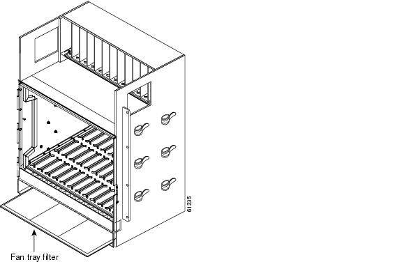
The ONS 15454 SDH contains a reusable filter that you should remove and visually inspect approximately every 30 days, depending on the cleanness of the operating environment. For more information about filter brackets and air filter installation, see Chapter 1 in the Cisco ONS 15454 SDH Installation and Operations Guide.
The air filter is made of gray, open-celled, polyurethane foam that is specially coated to provide fire and fungi resistance. Figure 4-1 illustrates a reusable fan tray air filter in an external filter bracket.
If the air filter is inside the fan-tray assembly, go directly to the "Fan-Tray Assembly" procedure to remove the fan tray.
Figure 4-1 Reusable fan tray filter in external filter brackets
Procedure: Inspect and Clean Reusable Air Filter
Purpose
Use this procedure to clean the reusable air filter.
Tools/Equipment
Vacuum cleaner
Prerequisite Procedures
—
Onsite/Remote
Onsite
Step 1
Step 2
Step 3
Note
Step 4
Caution
Step 5
4.2 Fan-Tray Assembly
To replace the fan-tray assembly (FTA), it is not necessary to move any of the cable management facilities. You can remove the fan-tray assembly using the retractable handles and replace it by pushing until it plugs into the receptacle on the back panel.
Purpose
This procedure replaces an existing FTA with a new FTA.
Tools/Equipment
Replacement FTA
Prerequisite Procedures
Procure necessary part number
Onsite/Remote
Onsite
Caution
Caution
Note
Procedure: Replace the Fan-Tray Assembly
Purpose
Use this procedure to replace the fan-tray assembly.
Tools/Equipment
Pinned hex key
Prerequisite Procedures
—
Onsite/Remote
Onsite
Step 1
a.
The ONS 15454 SDH comes with a pinned hex key for locking and unlocking the front door. Turn the key counterclockwise to unlock the door and clockwise to lock it.
b.
c.
Step 2
a.
b.
c.
Step 3
Step 4
Step 5
Step 6
Caution
Step 7
If you are replacing the fan-tray air filter and it is installed in the external bottom bracket, you can slide the existing air filter out of the bracket and replace it at any time. For more information on the fan-tray air filter, see the "Air Filter Inspection" section.
Step 8
The fans should start running immediately.
Step 9
Step 10
Step 11
4.3 System Reset
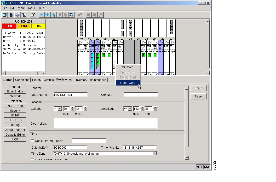
You can reset the ONS 15454 SDH TCC-I cards by using the Cisco Transport Controller (CTC) software or by physically resetting a TCC-I card (card pull). A software-initiated reset reboots the TCC-I card and reloads the operating system and the application software. If a card pull is performed, it carries out these tasks and temporarily powers down the TCC-I card, clearing all buffer memory.
You can initiate a software reset for an active TCC-I card or a standby TCC-I card without affecting traffic. But a card pull should only be performed on a standby TCC-I. If you need to pull an active TCC-I card, first you should initiate a software reset on a card to put it into standby mode.
Procedure: Initiate a Software Reset
Purpose
Use the CTC software to reset the ONS 15454 SDH.
Tools/Equipment
Workstation configured for CTC software
Prerequisite Procedures
—
Onsite/Remote
Onsite
Step 1
Step 2
Step 3
Figure 4-2 Resetting from the TCC-I card pull-down menu
Step 4
Step 5
Step 6
•
•
Procedure: Reset the TCC-I using a Card Pull
Purpose
Reset TCC-I card physically by removing and reseating card
Tools/Equipment
Workstation configured for CTC software
Prerequisite Procedures
—
Onsite/Remote
Onsite
Caution
Caution
Note
Step 1
Step 2
Step 3
Step 4
Note
Note
Note
4.4 Database Backup and Restoration
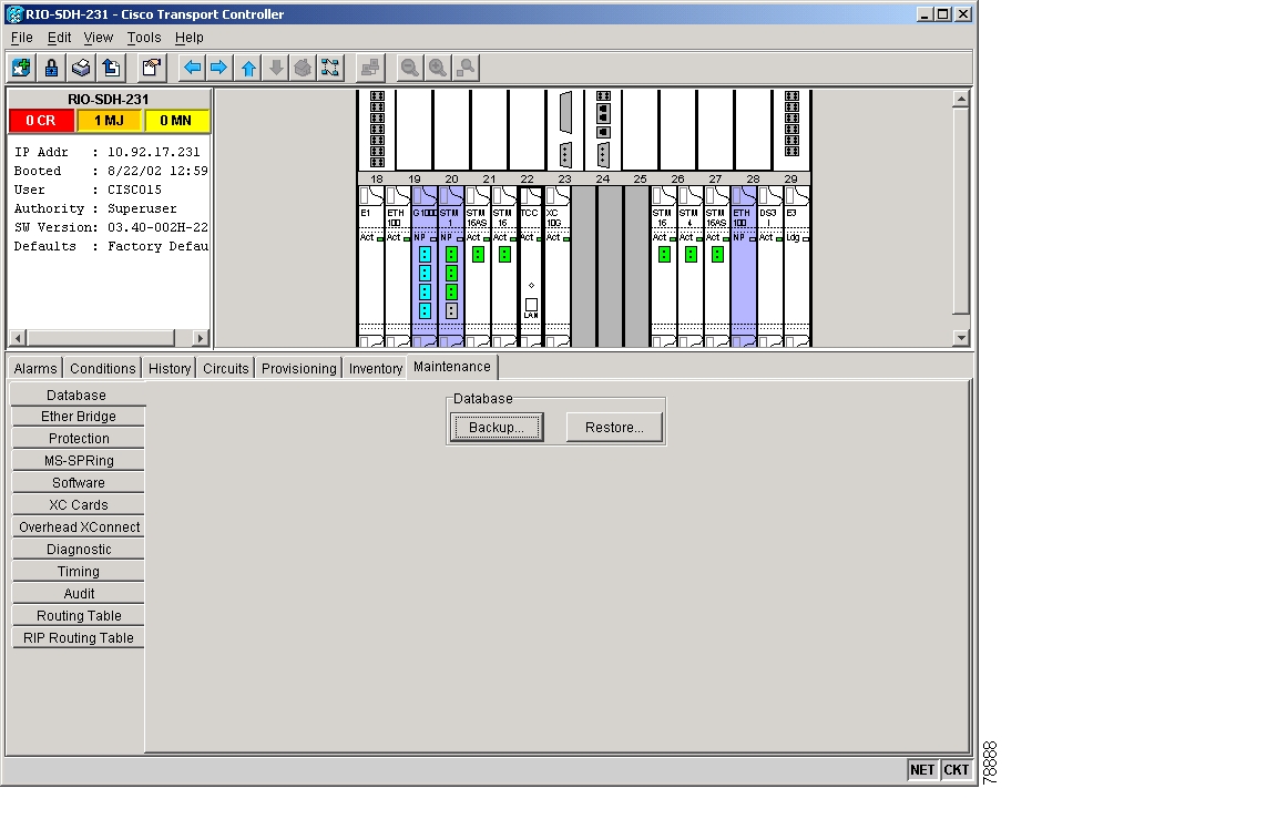
When dual TCC-I cards are installed in the ONS 15454 SDH, each TCC-I card hosts a separate copy of the database. If the working TCC-I card database fails, the protect card database is available. You can store a backup version of the database on a CTC software workstation. This off-system storage should be part of regular ONS 15454 SDH maintenance at approximately weekly intervals. It should also be performed to prepare an ONS 15454 SDH for disasters.
Note
Note
Note
Procedure: Back Up the Database
Purpose
This procedure backs up an ONS 15454 SDH database.
Tools/Equipment
Workstation configured for CTC software
Prerequisite Procedures
—
Onsite/Remote
Onsite
Note
Step 1
Step 2
Figure 4-3 Backing up the TCC-I card database
Step 3
Step 4
Step 5
Step 6
Step 7
Figure 4-4 Confirming a database backup is complete
Procedure: Restore the Database
Purpose
Restoring the data base of a node
Tools/Equipment
Workstation configured for CTC software
Prerequisite Procedures
—
Onsite/Remote
Onsite
Step 1
Step 2
Step 3
Step 4
Step 5
The file probably has a .db extension.
Step 6
Caution
Figure 4-5 Restoring the database—Traffic loss warning
Step 7
Figure 4-6 Restoring the database—In-process notification
Step 8
Note
Step 9
Note
4.5 Restore the Node to Factory Configuration
Purpose
Use this procedure to initiate a process that will automatically load and activate a software package and restore the database from a database backup file that was obtained at the time of installation. This process is performed with the RE-INIT.jar utility, also called the reinitialization (reinit) tool.
Tools/Equipment
CD containing the software, the node's NE defaults, and the reinitialization tool. JRE 1.3.1_02 must also be installed on the computer you will use to perform this procedure.
Prerequisite Procedures
Back Up the Database and the backup file which was obtained at installation
Onsite/Remote
Onsite (if you are replacing a TCC-I card) or remote
Caution
Caution
Note
Note
Step 1
Step 2
Step 3
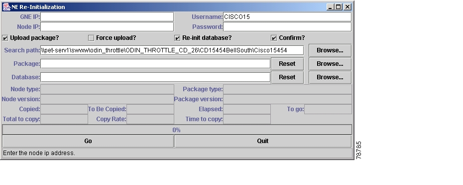
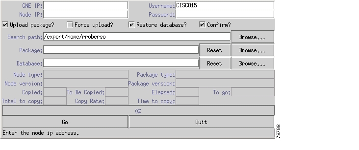
You can use the reinitialization tool to upload the software package, restore the node's database, or both by checking the appropriate fields shown below in Figure 4-7. The default setting for this tool is shown with both upload package (software) and restore database selected.
Procedure: Use the Reinitialization Tool in Windows
Note
Step 1
Step 2
Step 3
Step 4
•
•
•
Figure 4-7 Reinitialization tool in Windows
Step 5
a.
b.
c.
d.
Caution
e.
Caution
f.
g.
h.
Figure 4-8 Confirm NE Restoration
Step 6
a.
b.
c.
d.
e.
f.
g.
Step 7
a.
b.
c.
d.
e.
f.
g.
Step 8
Procedure: Use the Reinitialization Tool in Unix
Note
Step 1
Step 2
Step 3
Figure 4-9 The reinitialization tool in UNIX
Step 4
•
•
•
Step 5
a.
b.
c.
d.
Caution
If you upload the NE defaults database instead of a backed-up database, you will eliminate any existing provisioning on the node (including circuits and timing).
e.
f.
g.
h.
Step 6
a.
b.
c.
d.
e.
f.
g.
Step 7
a.
b.
c.
d.
e.
f.
g.
Step 8
a.
b.
c.
d.
e.
f.
g.
Step 9
4.6 Card Replacement
Cards can be replaced with the same type of card or with a different type.
•
•
Note
Caution
Note
Procedure: Replace an In-Service XC10G Card
Purpose
Replacing an in-service XC10G card
Tools/Equipment
—
Prerequisite Procedures
—
Onsite/Remote
Onsite
Caution
Note
Note
Step 1
a.
b.
c.
<------East [Node A] West------East [Node B] West------East [Node C] West------>
Before setting the lockout, verify that the MS-SPRing is not switched. Traffic can be lost if the MS-SPRing is switched when the lockout is set. In a 1+1 protection scheme, place a lockout on the protect card and verify that traffic is traveling over the working span before setting the lockout.
Step 2
Note
If the card to be replaced is already standby, go to Step 4.
Step 3
a.
b.
c.
Note
Step 4
Step 5
Step 6
Procedure: Replace a TCC-I Card
Caution
Step 1
Step 2
Step 3
Note
Procedure: Reset an STM-N Card
Note
Note
Note
Warning
Warning
Step 1
If the card is not standby, go to Step 2.
Step 2
Step 3
Step 4
<------East [Node A] West------East [Node B] West------East [Node C] West------>
You do not need to place lockouts on Node B. Before setting the lockout, verify that the MS-SPRing is not switched. Traffic can be lost if the MS-SPRing is switched when the lockout is set. In a 1+1 protection scheme, place a lockout on the protect card and verify that traffic is traveling over the working span before setting the lockout.
Procedure: Replace an In-Service STM-N Card in 1+1 Configuration
Purpose
Replacing an in-service STM-N card
Tools/Equipment
—
Prerequisite Procedures
—
Onsite/Remote
Onsite
Caution
Step 1
A green LED indicates an active card. A yellow LED indicates a standby card.
Note
Step 2
a.
b.
c.
Note
Step 3
Step 4
Procedure: Reset an Electrical Card (E1-N-14, DS3i-N-12, or E3-12)
Purpose
Resetting an electrical card
Tools/Equipment
—
Prerequisite Procedures
—
Onsite/Remote
Onsite
Note
Note
Note
Take these precautions before performing an electrical card reset to avoid causing a 1:1 or 1:N protection switch.
Step 1
If the card is not standby, go to Step 2.Ensure that the working span is active on the local and remote nodes.
Step 2
Step 3
<------East [Node A] West------East [Node B] West------East [Node C] West------>
Before the lockout is set, verify that the MS-SPRing is not switched. Traffic can be lost if a lockout is set when the MS-SPRing is switched.In a 1:1 protection scheme, place a lockout on the protect card and verify that traffic is traveling over the working span before setting the lockout.
Procedure: Replace an In-Service Electrical Card (E1-N-14, DS3i-N-12, or E3-12)
Purpose
Replacing an in-service electrical card
Tools/Equipment
—
Prerequisite Procedures
—
Onsite/Remote
Onsite
Caution
Step 1
The active card ACT/STBY LED is green. The standby card ACT/STBY LED is yellow.
Note
Step 2
a.
b.
c.
d.
Note
Step 3
Step 4
a.
b.
c.
d.
Procedure: Replace an FMEC Card
Caution
Note
Step 1
Note
Step 2
Step 3
Step 4
The replacement card is now ready for traffic. The traffic starts automatically.
Procedure: Replace an MIC-A/P Card or MIC-C/T/P Card
Purpose
Replacing an MIC-A/P or MIC-C/T/P card
Tools/Equipment
—
Prerequisite Procedures
—
Onsite/Remote
Onsite
Caution
Note
Step 1
Note
Step 2
Step 3
Step 4
Step 5
Note
4.7 Span Upgrade
A span includes the set of optical fiber ("lines") between two ONS 15454 SDH nodes. A span upgrade raises the STM-N signal transmission rate of all the lines constituting the spans. It is done by coordinated line upgrades that move traffic from lower-rate optical card(s) to higher-rate optical card(s). No other span attributes are changed.
Only single-port cards can be upgraded. You can upgrade the following ONS 15454 SDH cards in an in-service span:
•
•
•
When a span is upgraded, the higher-rate line card must replace the lower-rate card in the same slot. If the spans to be upgraded are part of a ring topology, all spans in the ring must be upgraded. The protect configuration (two-fiber MS-SPRing, four-fiber MS-SPRing, or 1+1) that was used with lower-rate optical card is retained in the higher-rate upgrade.
Span upgrades can be performed using the CTC software upgrade wizard, or they can be performed manually. To use the wizard, follow the procedure in the "Span Upgrade Wizard" section. To upgrade a span manually, follow the procedures in the "Manual Span Upgrades" section.
Note
4.7.1 Span Upgrade Wizard
The Span Upgrade Wizard automates all steps in the manual span upgrade procedure (MS-SPRing and 1+1). The Wizard can upgrade both lines on one side of a four-fiber MS-SPRing or both lines of a 1+1 group. The Wizard upgrades MSPs and two-fiber MS-SPRings one line at a time. The Span Upgrade Wizard requires that spans have DCC enabled.
Note
Note
Procedure: Span Upgrade Wizard
Purpose
Upgrading a span
Tools/Equipment
STM cards that support the new line rate
Prerequisite Procedures
—
Onsite/Remote
Onsite
Note
Note
Note
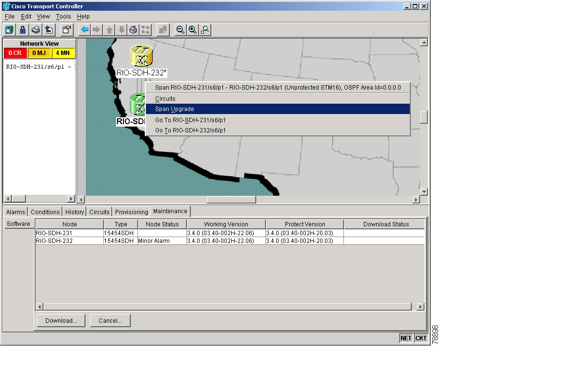
Step 1
Step 2
Step 3
Note
Figure 4-10 Span upgrade on shortcut menu
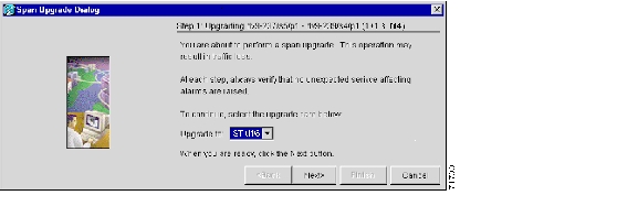
A Span Upgrade Dialog box appears showing Step 1 of the wizard ( Figure 4-11).
Figure 4-11 Beginning the Span Upgrade wizard
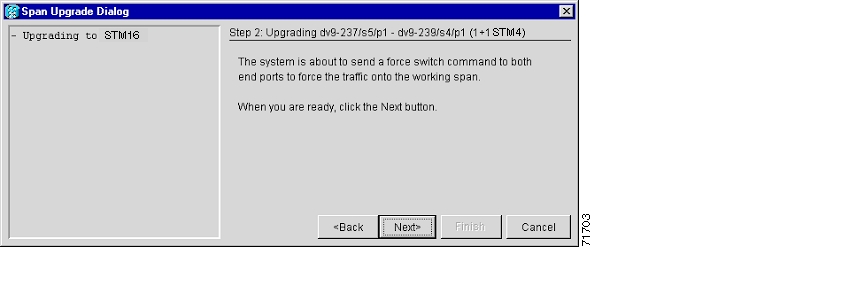
Step 4
Figure 4-12 Sending a force switch command
Step 5
Note
Figure 4-13 Waiting for a force switch command to take effect
Step 6
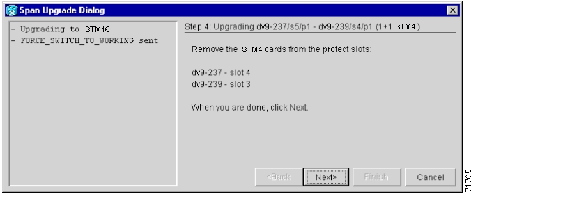
Figure 4-14 Removing the STM-N cards from the protect slots
Step 7
Step 8
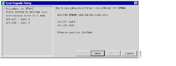
Figure 4-15 Inserting the STM-N cards into the protect slots
Step 9
Step 10
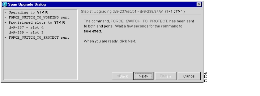
Figure 4-16 Sending a force switch command
Step 11
Figure 4-17 Waiting for the force switch command to take effect
Step 12
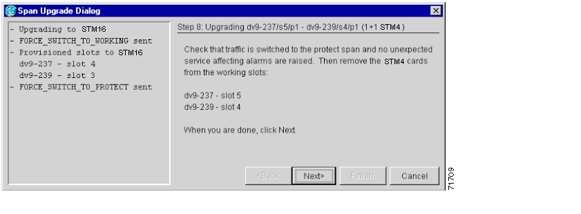
Figure 4-18 Removing the STM-N cards from the working slots
Step 13
Step 14
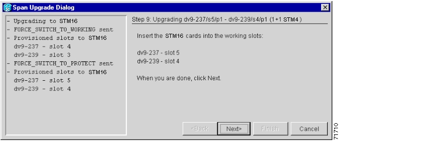
Figure 4-19 Inserting the STM-N cards into the working slots
Step 15
Step 16
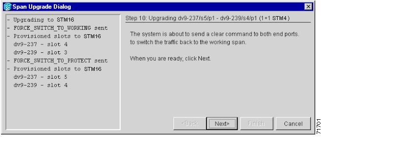
Figure 4-20 Sending a clear command
Step 17
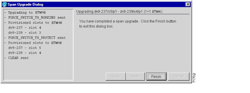
Figure 4-21 Completing the Span Upgrade wizard
Step 18
4.7.2 Manual Span Upgrades
The manual upgrade procedures require at least two technicians (one at each end of the span). The technicians must be able to communicate with each other during the upgrade. The upgrade procedures do not affect service. They cause no more than three switches with switch times of less than 50 ms.
During upgrade, some minor alarms and conditions occur and clear automatically. However, no service-affecting alarms (SA, Major, or Critical) should be expected. If any service-affecting alarms occur, Cisco recommends backing out of the procedure. Choose from four manual span upgrade options.
•
•
•
•
Procedure: Manually Upgrade a Span on a Two-Fiber MS-SPRing
Purpose
This procedure manually upgrades a span on a two-fiber MS-SPRing.
Tools/Equipment
STM cards that support the new line rate
Prerequisite Procedures
—
Onsite/Remote
Onsite
Note
Step 1
Step 2
Step 3
Step 4
Step 5
a.
b.
c.
Step 6
Step 7
Step 8
Step 9
Step 10
Step 11
Step 12
Step 13
Step 14
a.
b.
c.
Step 15
Procedure: Manually Upgrade a Span on a Four-Fiber MS-SPRing
Purpose
Manually upgrading a span on a four-fiber MS-SPRing
Tools/Equipment
STM cards that support the new line rate
Prerequisite Procedures
—
Onsite/Remote
Onsite
When upgrading a four-fiber MS-SPRing, you can upgrade both working and protect lines with a single force switch.
Note
Step 1
Step 2
Step 3
Step 4
Step 5
a.
b.
c.
Step 6
Step 7
Step 8
Step 9
Step 10
Step 11
Step 12
Step 13
Step 14
a.
b.
c.
Step 15
Procedure: Manually Upgrade a Span on a 1+1 Group
When upgrading a 1+1 group, upgrade the working and protect span regardless of which line is active. Both lines in a 1+1 group must be upgraded before added bandwidth will be available.
Purpose
Upgrading a span on a 1+1 group manually
Tools/Equipment
STM cards that support the new line speed
Prerequisite Procedures
—
Onsite/Remote
Onsite
Step 1
Step 2
Step 3
Step 4
Step 5
a.
b.
c.
d.
Step 6
Step 7
Step 8
Step 9
Step 10
Step 11
Step 12
Step 13
Step 14
a.
b.
c.
d.
Note
Step 15
4.8 Inspect and Clean Fiber Connectors
Warning
Caution
Caution
Caution
Step 1
Step 2
Note
Step 3
Step 4
Step 5
Step 6
Procedure: Inspect a Fiber Connector
Purpose
Inspecting optical connectors
Tools/Equipment
•
•
•
Prerequisite Procedures
—
Onsite/Remote
Onsite
Step 1
Step 2
Step 3
Procedure: Clean and Scope Fiber Connectors, Using Alcohol and Dry Wipes
Warning
Step 1
Step 2
Step 3
Step 4
Step 5
Note
Procedure: Clean and Scope Fiber Connectors, Using Cletop
Step 1
Step 2
Step 3
Step 4
Step 5
Note
Procedure: Clean a Fiber Adapter
Purpose
This task is used to clean fiber adapters.
Tools/Equipment
Cletop stick swab
Prerequisite Procedures
—
Onsite/Remote
Onsite
Step 1
Step 2
Step 3
Procedure: Clean a Feedthrough Connector
Purpose
Cleaning a feedthrough connector
Tools/Equipment
Compressed air
Prerequisite Procedures
—
Onsite/Remote
Onsite
Step 1
Step 2
Step 3
4.9 Powering Down a Node
Note
Note
Procedure: Power Down a Node
Step 1
Step 2
To determine whether the node is part of a working network, click Go to the Network View in the CTC node view, and determine whether the node is connected to other nodes on the map by spans.
To determine what kind of configuration the node is included in (if it is still part of a working network), log into the node if you have not done so already and click the Provisioning > MS-SPRing tab in the CTC node (default login) view. If a ring is present on the tab, the node is part of a two- or four-fiber MS-SPRing. If it is not present, but still shown on the network view map, it is an SNMP or linear ADM node.
•
•
Note
Step 3
a.
b.
If no circuits are displayed, skip to Step 4.
Step 4
Step 5
Step 6
Step 7
Step 8
Step 9
Step 10
Step 11
Step 12
Step 13
Step 14
Step 15
Step 16
Step 17
4.10 Powering Up a Node
Note
Procedure: Power Up a Node
Purpose
This procedure powers up a node.
Tools/Equipment
—
Prerequisite Procedures
—
Onsite/Remote
Onsite
Step 1
Step 2
Step 3
Step 4
Step 5
Step 6
Step 7
Step 8
Step 9
Note
Step 10
Step 11
Step 12
Step 13
Step 14
Step 15
Step 16
![]()
![]()
![]()
![]()
![]()
![]()
![]()
![]()
Posted: Sat Sep 24 13:47:55 PDT 2005
All contents are Copyright © 1992--2005 Cisco Systems, Inc. All rights reserved.
Important Notices and Privacy Statement.