|
|

Table Of Contents
3.2 Electrical Card Protection
3.2.4 Electrical Card Protection and the FMECs
3.5 Unprotected Cards (1:0 Protection)
3.6 Timing Communications and Control-International (TCC-I) Card
3.6.2 TCC-I Card-Level Indicators
3.6.3 Network-Level Indicators
3.7.1 XC10G Card-Level Indicators
3.7.2 XC10G Card Specifications
3.8 Alarm Interface Controller-International Card
3.8.1 AIC-I Card-Level Indicators
3.8.5 Data Communication Channel
3.9.1 E1-N-14 Card-Level Indicators
3.9.2 E1-N-14 Port-Level Indicators
3.10.1 E3-12 Card-Level Indicators
3.10.2 E3-12 Port-Level Indicators
3.11.1 DS3i-N-12 Card-Level Indicators
3.11.2 DS3i-N-12 Port-Level Indicators
3.11.3 DS3i-N-12 Card Specifications
3.12.1 BLANK Card Specifications
3.14.1 FMEC-E3/DS3 Card Specifications
3.15.1 FMEC-DS1/E1 Card Specifications
3.16.1 FMEC-BLANK Card Specifications
3.17.1 MIC-A/P Card Specifications
3.18.1 MIC-C/T/P Port-Level Indicators
3.18.2 MIC-C/T/P Card Specifications
3.19 OC3 IR 4/STM1 SH 1310 Card
3.19.1 OC3 IR 4/STM1 SH 1310 Card-Level Indicators
3.19.2 OC3 IR 4/STM1 SH 1310 Card Specifications
3.20 OC12 IR/STM4 SH 1310 Card
3.20.1 OC12 IR/STM4 SH 1310 Card-Level Indicators
3.20.2 OC12 IR/STM4 SH 1310 Port-Level Indicators
3.20.3 OC12 IR/STM4 SH 1310 Card Specifications
3.21 OC12 LR/STM4 LH 1310 Card
3.21.1 OC12 LR/STM4 LH 1310 Card-Level Indicators
3.21.2 OC12 LR/STM4 LH 1310 Port-Level Indicators
3.21.3 OC12 LR/STM4 LH 1310 Card Specifications
3.22 OC12 LR/STM4 LH 1550 Card
3.22.1 OC12 LR/STM4 LH 1550 Card-Level Indicators
3.22.2 OC12 LR/STM4 LH 1550 Port-Level Indicators
3.22.3 OC12 LR/STM4 LH 1550 Card Specifications
3.23 OC12 IR/STM4 SH 1310-4 Card
3.23.1 OC12 IR/STM4 SH 1310-4 Card-Level Indicators
3.23.2 OC12 IR/STM4 SH 1310-4 Port-Level Indicators
3.23.3 OC12 IR/STM4 SH 1310-4 Card Specifications
3.24 OC48 IR/STM16 SH AS 1310 Card
3.24.1 OC48 IR/STM16 SH AS 1310 Card-Level Indicators
3.24.2 OC48 IR/STM16 SH AS 1310 Port-Level Indicators
3.24.3 OC48 IR/STM16 SH AS 1310 Card Specifications
3.25 OC48 LR/STM16 LH AS 1550 Card
3.25.1 OC48 LR/STM16 LH AS 1550 Card-Level Indicators
3.25.2 OC48 LR/STM16 LH AS 1550 Port-Level Indicators
3.25.3 OC48 LR/STM16 LH AS 1550 Card Specifications
3.26 OC48 ELR/STM16 EH 100 GHz Cards
3.26.1 OC48 ELR/STM16 EH 100 GHz Card-Level Indicators
3.26.2 OC48 ELR/STM16 EH 100 GHz Port-Level Indicators
3.26.3 OC48 ELR/STM16 EH 100 GHz Card Specifications
3.27 OC192 LR/STM64 LH 1550 Card
3.27.1 OC192 LR/STM64 LH 1550 Card-Level Indicators
3.27.2 OC192 LR/STM64 LH 1550 Port-Level Indicators
3.27.3 OC192 LR/STM64 LH 1550 Card Specifications
3.28.1 E100T-G Card-Level Indicators
3.28.2 E100T-G Port-Level Indicators
3.28.3 E100T-G Card Specifications
3.29.1 E1000-2-G Card-Level Indicators
3.29.2 E1000-2-G Port-Level Indicators
3.29.3 E1000-2-G Card Specifications
3.30.1 G1000-4 Card-Level Indicators
3.30.2 G1000-4 Port-Level Indicators
3.30.3 G1000-4 Card Specifications
Card Reference
This chapter describes the Cisco ONS 15454 SDH cards. It includes descriptions, hardware specifications, and block diagrams for each card. For installation and card turn-up procedures, refer to Chapter 1 of the Cisco ONS 15454 SDH Installation and Operations Guide, R3.4.
3.1 Overview
The cards for the ONS 15454 SDH include Front Mount Electrical Connection cards (FMECs), common control cards, electrical cards, optical cards, and Ethernet cards. Each card is marked with a symbol that corresponds to a slot (or slots) on the ONS 15454 SDH shelf assembly. The cards are then installed into slots displaying the same symbols (refer to the Cisco ONS 15454 SDH Installation and Operations Guide, R3.4 for a list of slots/symbols). The overview in this section provides a summary of the cards.
3.1.1 Common Control Cards
Table 3-1 shows available common control cards for the ONS 15454 SDH.
Power supply and alarming interfaces are dealt with in the Electrical Cards section of this chapter.
3.1.2 Electrical Cards
Table 3-2 shows available electrical cards for the ONS 15454 SDH.
3.1.3 Optical Cards
Table 3-3 shows available optical cards for the ONS 15454 SDH.
3.1.4 Ethernet Cards
Table 3-4 shows available Ethernet cards for the ONS 15454 SDH. The Ethernet cards reduce the need for certain external Ethernet aggregation equipment such as hubs or switches.
3.1.5 Card Power Consumption
Table 3-5 shows power consumption per card.
Note
The ONS 15454 SDH is a flexible metro optical transport system supporting a wide variety of applications. The power consumption of the shelf assembly varies depending upon shelf configuration. Design your power distribution network based on your maximum ONS 15454 SDH system power draw, or the ONS 15454 SDH's maximum rated shelf power draw.
If you select to design your power plant to your maximum planned ONS 15454 SDH system configuration, the Cisco ONS 15454 SDH Troubleshooting and Maintenance Guide, R3.4 lists the power consumption for each card that can be used to determine your maximum ONS 15454 SDH system power draw. The general guideline for fuse selection is 20% above the maximum calculated system power draw.
If you design your power system to the ONS 15454 SDH's maximum rated shelf power draw, Cisco recommends that you select a power distribution system supporting a minimum capacity of 30A for each A and B power feeder on each ONS 15454 SDH shelf assembly. Feeder lines should be fused at 30A. This recommendation is based on the shelf assembly's current rated maximum power draw of 30A at -48 VDC. The maximum power draw configuration on the ONS 15454 SDH, based on the hardware available with Release 3.4, requires 30A at -48 VDC.3.2 Electrical Card Protection
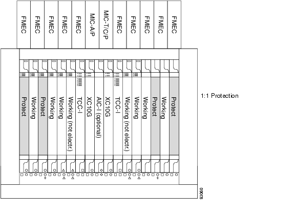
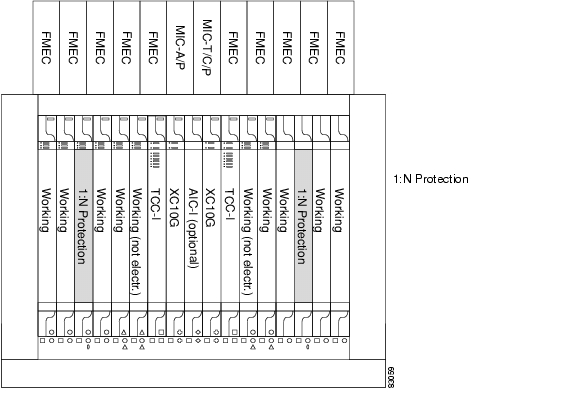
The ONS 15454 SDH provides a variety of electrical card protection methods. This section describes the protection options. Figure 3-1 shows a 1:1 protection scheme and Figure 3-2 shows a 1:N protection scheme.
3.2.1 1:0 Protection
The term 1:0 protection is sometimes used for an unprotected configuration.
3.2.2 1:1 Protection
In 1:1 protection, a working card is paired with a protect card of the same type. If the working card fails, the traffic from the working card switches to the protect card.When the failure on the working card is resolved, traffic automatically reverts to the working card. Figure 3-1 shows the ONS 15454 SDH in a 1:1 protection configuration; Slot 1 is protecting Slot 2, Slot 3 is protecting Slot 4, Slot 17 is protecting Slot 16, and Slot 15 is protecting Slot 14. Each working card is paired with a protect card. Slots 6 and 12 are not used for electrical cards. They have no corresponding FMEC slots.
Figure 3-1 ONS 15454 SDH cards in a 1:1 protection configuration
3.2.3 1:N Protection
1:N protection allows a single card to protect several working cards. An E1-N-14 card protects up to four E1-N-14 cards, and a DS3i-N-12 card protects up to four DS3i-N-12 cards.
Currently, 1:N protection operates only at the E-1 and DS-3 levels. The 1:N protect cards must match the levels of their working cards. For example, an E1-N-14 protects only E1-N-14 cards, and a DS3i-N-12 protects only DS3i-N-12 cards.
The physical E-1 or DS-3 ports on the ONS 15454 SDH FMEC cards use the working card until the working card fails. When the node detects this failure, the protection card takes over the physical E-1 or DS-3 electrical interfaces through the relays and signal bridging on the backplane. Figure 3-2 shows the ONS 15454 SDH in a 1:N protection configuration. Each side of the shelf assembly has only one card protecting all of the cards on that side.
Figure 3-2 ONS 15454 SDH cards in a 1:N protection configuration
3.2.3.1 Revertive Switching
1:N protection supports revertive switching. Revertive switching sends the electrical interfaces back to the original working card after the card comes back online. Detecting an active working card triggers the reversion process. There is a variable time period for the lag between detection and reversion, called the revertive delay, which you can set using Cisco Transport Controller (CTC). For instructions, refer to the Cisco ONS 15454 SDH Installation and Operations Guide, R3.4. All cards in a protection group share the same reversion settings. 1:N protection groups default to automatic reversion.
3.2.3.2 1:N Protection Guidelines
Several rules apply to 1:N protection groups in the ONS 15454 SDH:
•
•
•
The ONS 15454 SDH supports 1:N equipment protection for all add/drop multiplexer configurations (ring, linear, and terminal), as specified by ITU-T G.841.
The ONS 15454 SDH automatically detects and identifies a 1:N protection card when the card is installed in Slot 3 or Slot 15. However, the slot containing the 1:N card in a protection group must be manually provisioned as a protect slot because by default, all cards are working cards.
3.2.4 Electrical Card Protection and the FMECs
Note
Note
3.3 Optical Card Protection
The ONS 15454 SDH currently supports 1+1 span protection to create redundancy for optical cards. Optical cards in any two slots can be paired for protection. 1+1 protection pairs a single working card with a single dedicated protect card. If the working card fails, the protect card takes over.
With non-revertive 1+1 protection, when a failure occurs and the signal switches from the working card to the protect card, the signal stays switched to the protect card until it is manually switched back. Revertive 1+1 protection automatically switches the signal back to the working card when the working card comes back online.
3.4 Multiport Card Protection
For multiport cards such as the E1-N-14, the DS3i-N-12, and the OC3 IR 4/STM1 SH 1310, the ports on the protect card support the corresponding ports on the working card. With 1:1 or 1:N protection (electrical cards), the protect card must protect an entire slot. In other words, all the ports on the protect card will be used in the protection scheme.
With 1+1 protection (optical cards), protection can be assigned on a per-port basis. But the working and protect ports cannot be on the same card. In other words, any number of ports can be assigned as protection ports. On a four-port card, for example, you could assign one port as a protection port (protecting the corresponding port on the working card) and leave three ports unprotected. Conversely, you could assign three ports as protection ports and leave one port unprotected.
You create and modify protection schemes using CTC software. Refer to the Cisco ONS 15454 SDH Installation and Operations Guide, R3.4.
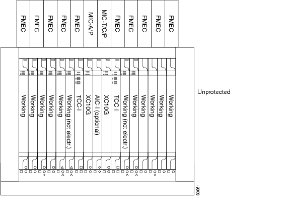
3.5 Unprotected Cards (1:0 Protection)
Unprotected cards are not included in a protection scheme; therefore, a card failure or a signal error results in lost data. An unprotected configuration is sometimes called 1:0 protection. Because no bandwidth is reserved for protection, unprotected schemes maximize the available ONS 15454 SDH bandwidth. Figure 3-3 shows the ONS 15454 SDH in an unprotected configuration. All cards are in a working state.
Figure 3-3 ONS 15454 SDH in an unprotected configuration
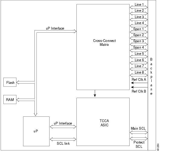
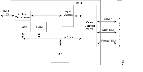
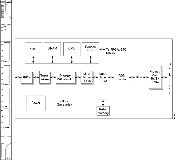
3.6 Timing Communications and Control-International (TCC-I) Card
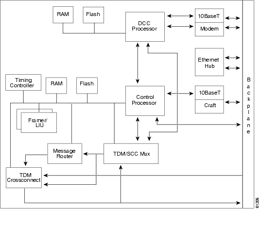
The TCC-I performs system initialization, provisioning, alarm reporting, maintenance, diagnostics, IP address detection/resolution, SDH section overhead (SOH) data communications channel (DCC) termination, and system fault detection for the ONS 15454 SDH. The TCC-I also ensures that the system maintains Stratum 3E (G.813) timing requirements. Figure 3-4 shows the TCC-I faceplate and Figure 3-5 shows a block diagram of the card.
Figure 3-4 TCC-I faceplate
Figure 3-5 TCC-I block diagram
3.6.1 TCC-I Functionality
The TCC-I supports multichannel, high-level data link control (HDLC) processing for the DCC. Up to 48 DCCs can be routed over the TCC-I and up to ten DCCs can be terminated at the TCC-I (subject to available optical digital communication channels). The TCC-I selects and processes ten DCCs to facilitate remote system management interfaces.
The TCC-I also originates and terminates a cell bus carried over the module. The cell bus supports links between any two cards in the node, which is essential for peer-to-peer communication. Peer-to-peer communication accelerates protection switching for redundant cards.
The node database, IP address, and system software are stored in TCC-I non-volatile memory, which allows quick recovery in the event of a power or card failure.
The TCC-I performs all system-timing functions for each ONS 15454 SDH. The TCC-I monitors the recovered clocks from each traffic card and two building integrated timing supply (BITS) ports for frequency accuracy. The TCC-I selects a recovered clock, a BITS or an internal Stratum 3E reference as the system-timing reference. You can provision any of the clock inputs as primary or secondary timing sources. A slow-reference tracking loop allows the TCC-I to synchronize with the recovered clock, which provides holdover if the reference is lost.
Install TCC-I cards in Slots 7 and 11 for redundancy. If the active TCC-I fails, traffic switches to the protect TCC-I. All TCC-I protection switches conform to protection switching standards when the bit error rate (BER) counts are not in excess of 1 * 10 exp - 3 and completion time is less than 50 ms.
The TCC-I uses a 10Base-T LAN port for user interfaces, led via the backplane to the port accessible on the front of the MIC-C/T/P FMEC.
Note
Note
Note
3.6.2 TCC-I Card-Level Indicators
The TCC-I faceplate has eight LEDs. The first two LEDs are card-level indicators. These indicators are described in Table 3-6.
3.6.3 Network-Level Indicators
The TCC-I faceplate has eight LEDs. Six LEDs are network-level indicators. These indicators are described in Table 3-7.
3.6.4 TCC-I Specifications
•
–
–
•
–
–
–
–
•
–
–
–
•
–
–
–
–
–
•
ONS 15454 SDH cards, when installed in a system, comply with these standards:
–
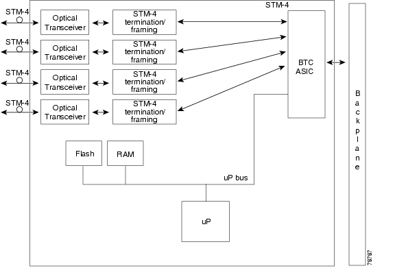
3.7 Cross Connect XC10G Card
The XC10G card cross connects STM-1, STM-4, STM-16, and STM-64 signal rates. The XC10G provides a maximum of 384 x 384 VC-4 non-blocking cross connections. Any STM-1 on any port can be connected to any other port, meaning that the STM cross-connections are non-blocking.
The XC10G faceplate, cross-connects, and a block diagram are shown in Figure 3-6, Figure 3-7, and Figure 3-8.
Note
Figure 3-6 XC10G faceplate
Figure 3-7 XC10G Cross-Connect matrix
Figure 3-8 XC10G block diagram
The XC10G card manages up to 192 bidirectional STM-1 cross-connects. The TCC-I assigns bandwidth to each slot on a per STM-1 basis. The XC10G card works with the TCC-I card to maintain connections and set up cross-connects within the system. The XC10G is required to operate the ONS 15454 SDH. You can establish cross-connect and provisioning information through the Cisco Transport Controller (CTC). The TCC-I establishes the proper internal cross-connect information and sends the setup information to the XC10G cross-connect card.
Note
3.7.1 XC10G Card-Level Indicators
The XC10G faceplate has two card-level LEDs, described in Table 3-8.
3.7.2 XC10G Card Specifications
•
–
–
–
•
–
–
–
–
–
•
ONS 15454 SDH cards, when installed in a system, comply with these standards:
–
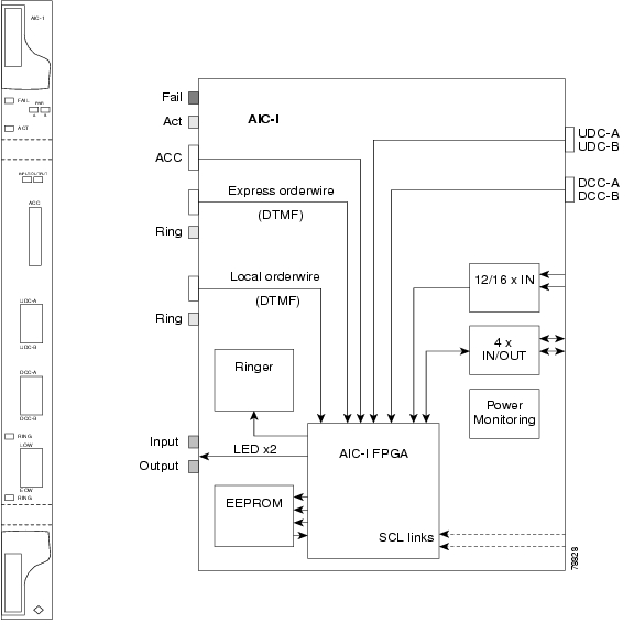
3.8 Alarm Interface Controller-International Card
The optional Alarm Interface Controller-International (AIC-I) card provides customer-defined alarm I/O, and supports user data and local and express orderwire. It provides 16 customer-defined input contacts and 4 customer-defined input/output contacts. It requires the MIC-A/P for connection to the alarm contacts. Figure 3-9 shows the AIC-I faceplate and a block diagram of the card.
Figure 3-9 AIC-I faceplate and block diagram
3.8.1 AIC-I Card-Level Indicators
The AIC-I card has eight card-level LED indicators, described in Table 3-9.
3.8.2 User-Defined Alarms
The AIC-I card provides input/output alarm contact closures. You can define up to sixteen external alarm inputs and four external alarm inputs/outputs (user configurable). The physical connections are made using the MIC-A/P. The alarms are defined using CTC. For instructions, refer to the Cisco ONS 15454 SDH Installation and Operations Guide, R3.4.
LEDs on the front panel of the AIC-I indicate the status of the alarm lines: one LED representing all the inputs and one LED representing all the outputs. External alarms (input contacts) are typically used for external sensors such as open doors, temperature sensors, flood sensors, and other environmental conditions. External controls (output contacts) are typically used to drive visual or audible devices such as bells and lights, but they can control other devices such as generators, heaters, and fans.
You can program each of the sixteen input alarm contacts separately. Choices include Alarm on Closure or Alarm on Open, an alarm severity of any level (Critical, Major, Minor, Not Alarmed, Not Reported), and Service Affecting or Non-Service Affecting alarm-service level, and a 63-character alarm description for CTC display in the alarm log. You cannot assign the fan-tray abbreviation for the alarm; the abbreviation reflects the generic name of the input contacts. The alarm condition remains raised until the external input stops driving the contact or you de-provision the alarm input.
The output contacts can be provisioned to close on a trigger or to close manually. The trigger can be a local alarm severity threshold, a remote alarm severity, or a virtual wire, as follows:
•
•
•
You can also program the output alarm contacts (external controls) separately. In addition to provisionable triggers, you can manually force each external output contact to open or close. Manual operation takes precedence over any provisioned triggers that might be present.
3.8.3 Orderwire
Orderwire allows a craftsperson to plug a phoneset into an ONS 15454 SDH and communicate with craftspeople working at other ONS 15454 SDHs or other facility equipment. The orderwire is a pulse code modulation (PCM) encoded voice channel that uses E1 or E2 bytes in the multiplex section overhead and in the regenerator section overhead.
The AIC-I allows simultaneous use of both local (section overhead signal) and express (line overhead channel) orderwire channels on an SDH ring or particular optics facility. Express orderwire also allows communication via regeneration sites when the regenerator is not a Cisco device.
You can provision orderwire functions with CTC similar to the current provisioning model for DCC channels. In CTC, you provision the orderwire communications network during ring turn-up so that all NEs on the ring can reach one another. Orderwire terminations (i.e., the optics facilities that receive and process the orderwire channels) are provisionable. Both express and local orderwire can be configured as on or off on a particular SDH facility. The ONS 15454 SDH supports up to four orderwire channel terminations per shelf. This allows linear, single ring, dual ring, and small hub-and-spoke configurations. Keep in mind that orderwire is not protected in ring topologies such as multiplex section-shared protection ring (MS-SPRing) and subnetwork connection protection (SNCP).
Caution
The ONS 15454 SDH implementation of both local and express orderwire is broadcast in nature. The line acts as a party line. Anyone who picks up the orderwire channel can communicate with all other participants on the connected orderwire subnetwork. The local orderwire party line is separate from the express orderwire party line. Up to four OC-N/STM-N facilities for each local and express orderwire are provisionable as orderwire paths.
Note
The AIC-I supports selective dual tone multifrequency (DTMF) dialing for telephony connectivity which causes specific or all ONS 15454 SDH AIC-Is on the orderwire subnetwork to "ring." The ringer/buzzer resides on the AIC-I. There is also a "ring" LED that mimics the AIC-I ringer. It flashes when a call is received on the orderwire subnetwork. A party line call is initiated by pressing *0000 on the DTMF pad. Individual dialing is initiated by pressing * and the individual four-digit number on the DTMF pad.
The orderwire ports are standard RJ-11 receptacles. The pins on the orderwire ports correspond to the tip and ring orderwire assignments. Orderwire pin assignments are described in Table 3-10. Figure 3-10 shows the RJ-11 cable.
Table 3-10 Orderwire Pin Assignments
1
Four-wire receive ring
2
Four-wire transmit tip
3
Two-wire ring
4
Two-wire tip
5
Four-wire transmit ring
6
Four-wire receive tip
Figure 3-10 RJ-11 cable connector
When provisioning the orderwire subnetwork, make sure that an orderwire loop does not exist. Loops cause oscillation and an unusable orderwire channel.
3.8.4 User Data Channel
The User Data Channel (UDC) features a dedicated data channel of 64 kBit/s (kbps) (F1 byte) between two nodes in an ONS 15454 SDH network. Each AIC-I card provides two UDCs, UDC-A and UDC-B, through separate RJ-11 connectors on the front of the AIC-I. Each UDC can be routed to an individual optical interface in the ONS 15454 SDH system. For instructions, refer to the Cisco ONS 15454 SDH Installation and Operations Guide, R3.4.
The UDC ports are standard RJ-11 receptacles. The UDC pin assignments are listed in Table 3-11. Figure 3-10 shows the RJ-11 cable connector.
Table 3-11 UDC Pin Assignments
1
For future use
2
TXN
3
RXN
4
RXP
5
TXP
6
For future use
3.8.5 Data Communication Channel
The Data Communication Channel (DCC) features a dedicated data channel of 576 kBit/s (kbps) (D4 to D12 bytes) between two nodes in an ONS 15454 SDH network. Each AIC-I card provides two DCCs, DCC-A and DCC-B, through separate RJ-45 connectors on the front of the AIC-I. Each DCC can be routed to an individual optical interface in the ONS 15454 SDH system. For instructions, refer to the Cisco ONS 15454 SDH Installation and Operations Guide, R3.4.
Note
The DCC ports are standard RJ-45 receptacles. The DCC pin assignments are described in Table 3-12.
Table 3-12 DCC Pin Assignments
1
TCLKP
2
TCLKN
3
TXP
4
TXN
5
RCLKP
6
RCLKN
7
RXP
8
RXN
3.8.6 AIC-I Specifications
•
–
–
–
–
–
–
–
•
–
–
–
–
–
–
•
–
–
Note
–
–
•
–
–
–
–
•
–
–
–
–
•
–
•
–
–
–
•
–
–
–
–
•
ONS 15454 SDH cards, when installed in a system, comply with these standards:
–
3.9 E1-N-14 Card
The fourteen-port ONS 15454 SDH E1-N-14 card provides fourteen ITU-compliant, G.703 E-1 ports. Each port of the E1-N-14 card operates at 2.048 MBit/s (Mbps) over a 120-ohm, twisted-pair copper cable (with FMEC-DS1/E1) or over a 75-ohm unbalanced coaxial cable (with FMEC-E1). Figure 3-11 shows the E1-N-14 faceplate and Figure 3-12 shows a block diagram of the card.
Figure 3-11 E1-N-14 faceplate
Figure 3-12 E1-N-14 block diagram
Each E1-N-14 port features ITU-T G.703 compliant outputs and inputs supporting cable losses of up to 6 dB at 1024 kHz. The E1-N-14 card supports 1:N (N <= 4) protection. You can also provision the E1-N-14 to monitor line and frame errors in both directions.
The E1-N-14 card can function as a working or protect card in 1:1 or 1:N protection schemes. If you use the E1-N-14 as a standard E-1 card in a 1:1 protection group, you can install the E1-N-14 card in any multispeed or high-speed card slot on the ONS 15454 SDH. If you use the card's 1:N functionality, you must install an E1-N-14 card in Slot 3 (for bank A) or Slot 15 (for bank B).
You can group and map E1-N-14 card traffic in VC-12 as per ITU-T G.707 to any other card in an ONS 15454 SDH node. For performance-monitoring purposes, you can gather bidirectional E-1 frame-level information (for example, loss of frame, parity errors, or CRC errors).
Note
3.9.1 E1-N-14 Card-Level Indicators
The E1-N-14 card faceplate has three LEDs, described in Table 3-13.
3.9.2 E1-N-14 Port-Level Indicators
You can obtain the status of the fourteen E-1 ports using the LCD screen on the ONS 15454 SDH fan-tray assembly. Use the LCD to view the status of any port or card slot; the screen displays the number and severity of alarms for a given port or slot. Refer to Chapter 1, "Alarm Troubleshooting," for a complete description of the alarm messages.
3.9.3 E1-N-14 Specifications
•
–
–
–
–
–
–
–
•
–
–
–
–
–
–
–
–
–
•
–
–
–
–
•
–
–
–
–
–
•
ONS 15454 SDH cards, when installed in a system, comply with these standards:
–
3.10 E3-12 Card
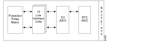
The twelve-port ONS 15454 SDH E3-12 card provides twelve ITU-compliant, G.703 E-3 ports per card. Each interface operates at 34.368 MBit/s (Mbps) over a 75-ohm coaxial cable (with FMEC-E3/DS3). The E3-12 card operates as a working or protect card in 1:1 protection schemes and as a working card in 1:N protection schemes. Figure 3-13 shows the E3-12 faceplates, and Figure 3-14 shows a block diagram of the card.
Figure 3-13 E3-12 faceplate
Figure 3-14 E3-12 block diagram
You can install the E3-12 card in any multispeed or high-speed card slot on the ONS 15454 SDH. Each E3-12 port features ITU-T G.703 compliant outputs supporting cable losses of up to 12 dB at 17184 kHz. The E3-12 card supports 1:1 protection.
Note
Note
3.10.1 E3-12 Card-Level Indicators
The E3-12 card faceplate has three LEDs, described in Table 3-14.
3.10.2 E3-12 Port-Level Indicators
You can find the status of the twelve E3-12 card ports using the LCD screen on the ONS 15454 SDH fan-tray assembly. Use the LCD to view the status of any port or card slot; the screen displays the number and severity of alarms for a given port or slot. Refer to Chapter 1, "Alarm Troubleshooting," for a complete description of the alarm messages.
3.10.3 E3-12 Specifications
•
–
–
–
–
–
–
•
–
–
–
–
–
–
–
–
–
•
–
•
–
–
–
–
•
–
–
–
–
–
•
ONS 15454 SDH cards, when installed in a system, comply with these standards:
–
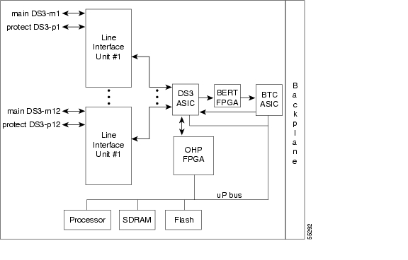
3.11 DS3i-N-12 Card
The twelve-port ONS 15454 SDH DS3i-N-12 card provides twelve ITU-T G.703, Telcordia GR-499, and ITU-T G.704 compliant DS-3 ports per card. Each port operates at 44.736 MBit/s (Mbps) over a 75-ohm coaxial cable (with FMEC-E3/DS3). The DS3i-N-12 can detect several different errored logic bits within a DS-3 frame. This function lets the ONS 15454 SDH identify a degrading DS-3 facility caused by upstream electronics (DS-3 Framer). In addition, DS-3 frame format auto detection and J1 path trace are supported. By monitoring additional overhead in the DS-3 frame, subtle network degradations can be detected. Figure 3-15 shows the DS3i-N-12 faceplate and Figure 3-16 shows a block diagram of the card.
Figure 3-15 DS3i-N-12 faceplate
Figure 3-16 DS3i-N-12 block diagram
The following list summarizes the DS3i-N-12 card features:
•
•
•
•
•
•
•
•
•
•
•
•
You can install the DS3i-N-12 card in any multispeed or high-speed card slot. Each DS3i-N-12 port features DSX-level outputs supporting distances up to 450 feet. With FMEC-E3/DS3, the card supports 1.0/2.3 Miniature Coax nonbalanced connectors.
The DS3i-N-12 can operate as the protect card in a 1:N (N < 4) DS-3 protection group. It has circuitry that allows it to protect up to four working DS3i-N-12 cards.
Note
3.11.1 DS3i-N-12 Card-Level Indicators
The DS3i-N-12 card faceplate has three LEDs, listed in Table 3-15.
3.11.2 DS3i-N-12 Port-Level Indicators
You can find the status of the DS3i-N-12 card ports using the LCD screen on the ONS 15454 SDH fan-tray assembly. Use the LCD to view the status of any port or card slot; the screen displays the number and severity of alarms for a given port or slot. Refer to Chapter 1, "Alarm Troubleshooting," for a complete description of the alarm messages.
3.11.3 DS3i-N-12 Card Specifications
•
–
–
–
–
–
–
Maximum 137 m (450 ft): 734A, RG59, 728A
Maximum 24 m (79 ft): RG179–
•
–
–
–
–
–
–
–
–
–
–
–
•
–
•
–
–
–
–
•
–
–
–
–
–
•
ONS 15454 SDH cards, when installed in a system, comply with these standards:
–
3.12 BLANK Card
The BLANK card provides EMC emission control for empty interface card slots. It also provides a way to close off the subrack front area, thus allowing air flow and convection to be maintained through the subrack. Figure 3-17 shows the BLANK card faceplate.
Figure 3-17 BLANK faceplate
You have to install the BLANK in every empty interface card slot to maintain EMC requirements of the system and proper air flow.
3.12.1 BLANK Card Specifications
•
–
–
–
•
–
–
–
•
ONS 15454 SDH cards, when installed in a system, comply with these standards:
–
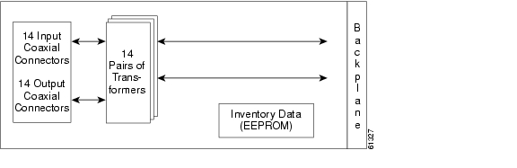
3.13 FMEC-E1 Card
The ONS 15454 SDH FMEC-E1 card provides front mount electrical connection for fourteen ITU-compliant, G.703 E-1 ports. With FMEC-E1, each E1-N-14 port operates at 2.048 MBit/s (Mbps) over a 75-ohm unbalanced coaxial 1.0/2.3 Miniature Coax connector. Figure 3-18 shows the FMEC-E1 faceplate, and Figure 3-19 shows a block diagram of the card.
Figure 3-18 FMEC-E1 faceplate
You can install the FMEC-E1 card in any EFCA (Electrical Facility Connection Assembly) slot from Slot 18 to 22 or Slot 25 to 29 on the ONS 15454 SDH. Each FMEC-E1 card port features E1-level inputs and outputs supporting cable losses of up to 6 dB at 1024 kHz.
Figure 3-19 FMEC-E1 block diagram
3.13.1 FMEC-E1 Specifications
•
–
–
–
–
–
•
–
–
–
–
–
–
•
–
•
–
–
–
•
–
–
–
–
–
•
ONS 15454 SDH cards, when installed in a system, comply with these standards:
–
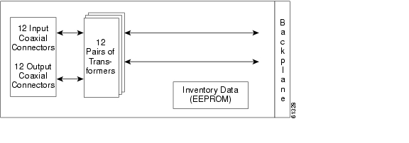
3.14 FMEC-E3/DS3 Card
The ONS 15454 SDH FMEC-E3/DS3 card provides front mount electrical connection for twelve ITU-compliant, G.703 E-3 or DS-3 ports. With FMEC-E3/DS3, each interface of an E3-12 card operates at 34.368 MBit/s (Mbps). Each interface of a DS3i-N-12 card operates at 44.736 MBit/s (Mbps) over a 75-ohm unbalanced coaxial 1.0/2.3 miniature coax connector. Figure 3-20 shows the FMEC-E3/DS3 faceplate and Figure 3-21 shows a block diagram of the card.
Figure 3-20 FMEC-E3/DS3 faceplate
You can install the FMEC-E3/DS3 card in any EFCA slot from Slot 18 to 22 or Slot 25 to 29 on the ONS 15454 SDH. Each FMEC-E3/DS3 card interface features E3-level or DS3-level inputs and outputs supporting cable losses of up to 12 dB at 17184 kHz for E3 signals, up to 137 m (450 ft) 734A, RG59, 728A per 24 m (79 ft) RG179 for DS3 signals.
Figure 3-21 FMEC-E3/DS3 block diagram
3.14.1 FMEC-E3/DS3 Card Specifications
•
–
–
–
–
–
•
–
–
–
–
–
–
•
–
–
–
–
–
Maximum 137 m (450 ft): 734A, RG59, 728A
Max 24 m (79 ft): RG179•
–
–
–
–
–
–
–
–
–
•
–
•
–
–
–
•
–
–
–
–
–
•
ONS 15454 SDH cards, when installed in a system, comply with these standards:
–
3.15 FMEC-DS1/E1 Card
The ONS 15454 SDH FMEC-DS1/E1 card provides front mount electrical connection for fourteen ITU-compliant, G.703 E-1 ports. With FMEC-DS1/E1, each E1-N-14 port operates at 2.048 MBit/s (Mbps) over a 120-ohm balanced cable via two 37-pin DB connectors. Figure 3-22 shows the FMEC-DS1/E1 faceplate, and Figure 3-23 shows a block diagram of the card.
Caution
Figure 3-22 FMEC-DS1/E1 faceplate
You can install the FMEC-DS1/E1 card in any EFCA slot from Slot 18 to 22 or Slot 25 to 29 on the ONS 15454 SDH. Each FMEC-DS1/E1 card interface features E1-level inputs and outputs supporting cable losses of up to 6 dB at 1024 kHz.
Figure 3-23 FMEC-DS1/E1 block diagram
3.15.1 FMEC-DS1/E1 Card Specifications
•
–
–
–
–
–
•
–
–
–
–
–
–
•
–
•
–
–
–
•
–
–
–
–
–
•
ONS 15454 SDH cards, when installed in a system, comply with these standards:
–
3.16 FMEC-BLANK Card
The FMEC-BLANK card provides EMC emission control for empty FMEC slots. It also provides a way to close off the EFCA area, thus allowing air flow and convection to be maintained through the EFCA. Figure 3-24 shows the FMEC-BLANK card faceplate.
Figure 3-24 FMEC-BLANK faceplate
You have to install the BLANK FMEC in every empty FMEC slot to maintain EMC requirements of the system and proper air flow.
3.16.1 FMEC-BLANK Card Specifications
•
–
–
–
•
–
–
–
3.17 MIC-A/P Card
The MIC-A/P card provides connection for one of the two possible redundant power supply inputs. It also provides connection for eight alarm outputs (coming from the TCC-I card) and for sixteen alarm inputs and four configurable alarm inputs/outputs. Its position is in Slot 23 in the center of the ONS 15454 SDH subrack EFCA area. Figure 3-25 shows the MIC-A/P faceplate and Figure 3-26 shows a block diagram of the card.
Figure 3-25 MIC-A/P faceplate
The following list summarizes MIC-A/P card features:
•
•
•
•
•
Note
Figure 3-26 MIC-A/P block diagram
3.17.1 MIC-A/P Card Specifications
•
–
Tolerance limits: -40.5 to -57.0 VDC–
•
–
–
–
•
–
–
–
•
–
–
–
•
–
–
–
–
–
•
ONS 15454 SDH cards, when installed in a node, comply with these standards:–
3.18 MIC-C/T/P Card
The MIC-C/T/P card provides connection for one of the two possible redundant power supply inputs. It also provides connection for system management serial port, system management LAN port, modem port (for future use), and system timing inputs and outputs. Place the MIC-C/T/P in Slot 24. Figure 3-27 shows the MIC-C/T/P card faceplate and Figure 3-28 shows a block diagram of the card.
Figure 3-27 MIC-C/T/P faceplate
Figure 3-28 MIC-C/T/P block diagram
The following list summarizes MIC-C/T/P card features:
•
•
•
•
•
•
Note
3.18.1 MIC-C/T/P Port-Level Indicators
The MIC-C/T/P card has one pair of LEDs, located on the RJ45 LAN connector. The green LED is illuminated when a link is present, and the yellow LED is illuminated when data is being transferred.
3.18.2 MIC-C/T/P Card Specifications
•
–
Tolerance limits: -40.5 to -57.0 VDC–
•
–
–
–
(120 ohms impedance, balanced, possible with external matching cable)–
–
•
–
–
–
(120 ohms Impedance, balanced, possible with external matching cable)–
–
•
–
–
–
•
–
–
•
–
–
–
•
–
–
–
–
–
•
ONS 15454 SDH cards, when installed in a system, comply with these standards:
–
3.19 OC3 IR 4/STM1 SH 1310 Card
The OC3 IR 4/STM1 SH 1310 card provides four intermediate or short range, ITU-T G.707- and G.957- compliant, SDH, STM-1 ports. Each port operates at 155.52 MBit/s (Mbps) over a single-mode fiber span. The card supports concatenated or non-concatenated payloads at the STM-1 signal level on a per VC-4 basis. Figure 3-29 shows the OC3 IR 4/STM1 SH 1310 faceplate and Figure 3-30 shows a block diagram of the card.
Warning
Figure 3-29 OC3 IR 4/STM1 SH 1310 faceplate
Figure 3-30 OC3 IR 4/STM1 SH 1310 block diagram
Warning
You can install the OC3 IR 4/STM1 SH 1310 card in any multispeed or high-speed card slot. The card can be provisioned as part of a SNCP or in an add/drop multiplexer/terminal monitor (ADM/TM) configuration. Each interface features a 1310-nm laser and contains a transmit and receive connector (labeled) on the card faceplate. The card uses SC connectors.
The OC3 IR 4/STM1 SH 1310 card supports 1+1 unidirectional and bidirectional protection switching. You can provision protection on a per port basis.
The OC3 IR 4/STM1 SH 1310 detects LOS, LOF, loss of pointer (LOP), multiplex section alarm indication signal (MS-AIS), and multiplex section far-nd receive failure (MS-FERF) conditions. Refer to Chapter 1, "Alarm Troubleshooting," for a description of these conditions. The card also counts section and line bit interleaved parity (BIP) errors.
To enable automatic protection switching (APS), the OC3 IR 4/STM1 SH 1310 extracts the K1 and K2 bytes from the SDH overhead to perform appropriate protection switches. The DCC bytes are forwarded to the TCC-I, which terminates the DCC.
3.19.1 OC3 IR 4/STM1 SH 1310 Card-Level Indicators
The OC3 IR 4/STM1 SH 1310 card has three card-level LED indicators, described in Table 3-16.
3.19.1.1 OC3 IR 4/STM1 SH 1310 Port-Level Indicators
You can find the status of the four card ports using the LCD screen on the ONS 15454 SDH fan-tray assembly. Use the LCD to view the status of any port or card slot; the screen displays the number and severity of alarms for a given port or slot. Refer to Chapter 1, "Alarm Troubleshooting," for a complete description of the alarm messages.
3.19.2 OC3 IR 4/STM1 SH 1310 Card Specifications
•
–
–
–
–
–
–
•
–
–
–
–
–
•
–
–
–
–
–
•
–
–
–
•
–
–
–
–
–
•
ONS 15454 SDH optical cards, when installed in a system, comply with these standards:–
–
3.20 OC12 IR/STM4 SH 1310 Card
The OC12 IR/STM4 SH 1310 card provides one intermediate or short range, ITU-T G.707- and G.957-compliant, SDH STM-4 port per card. The interface operates at 622.08 MBit/s (Mbps) over a single-mode fiber span. The card supports concatenated or non-concatenated payloads on a per VC-4 basis. Figure 3-31 shows the OC12 IR/STM4 SH 1310 faceplate and Figure 3-32 shows a block diagram of the card.
Warning
Figure 3-31 OC12 IR/STM4 SH 1310 faceplate
Figure 3-32 OC12 IR/STM4 SH 1310 block diagram
Warning
You can install the OC12 IR/STM4 SH 1310 card in any multispeed or high-speed card slot. You can provision the card as part of a multiplex section protection (MSP) or subnetwork connection (SNC) ring. In ADM/TM configurations, you can provision the card as either an access tributary or a transport span-side interface.
The OC12 IR/STM4 SH 1310 card interface features a 1310-nm laser and contains a transmit and receive connector (labeled) on the card faceplate. The OC12 IR/STM4 SH 1310 card uses SC optical connections and supports 1+1 unidirectional and bidirectional protection.
The OC12 IR/STM4 SH 1310 detects LOS, LOF, LOP, MS-AIS, and MS-FERF conditions. Refer to Chapter 1, "Alarm Troubleshooting," for a description of these conditions. The card counts section and line BIP errors.
To enable MSP, the OC12 IR/STM4 SH 1310 extracts the K1 and K2 bytes from the SDH overhead and processes them to switch accordingly. The DCC bytes are forwarded to the TCC-I card, which terminates the DCC.
3.20.1 OC12 IR/STM4 SH 1310 Card-Level Indicators
The OC12 IR/STM4 SH 1310 card has three card-level LED indicators, listed in Table 3-17.
3.20.2 OC12 IR/STM4 SH 1310 Port-Level Indicators
You can find the status of the OC12 IR/STM4 SH 1310 card port using the LCD screen on the ONS 15454 SDH fan-tray assembly. Use the LCD to view the status of any port or card slot; the screen displays the number and severity of alarms for a given port or slot. Refer to Chapter 1, "Alarm Troubleshooting," for a complete description of the alarm messages.
3.20.3 OC12 IR/STM4 SH 1310 Card Specifications
•
–
–
–
–
–
–
•
–
–
–
–
–
•
–
–
–
–
–
•
–
–
–
•
–
–
–
–
–
•
ONS 15454 SDH optical cards, when installed in a system, comply with these standards:–
–
3.21 OC12 LR/STM4 LH 1310 Card
The OC12 LR/STM4 LH 1310 card provides one long-range, ITU-T G.707- and G.957-compliant, SDH STM-4 port per card. The interface operates at 622.08 MBit/s (Mbps) over a single-mode fiber span. The card supports concatenated or non-concatenated payloads on a per VC-4 basis. Figure 3-33 shows the OC12 LR/STM4 LH 1310 faceplate and Figure 3-34 shows a block diagram of the card.
Warning
Figure 3-33 OC12 LR/STM4 LH 1310 faceplate
Figure 3-34 OC12 LR/STM4 LH 1310 block diagram
Warning
You can install the OC12 LR/STM4 LH 1310 card in any multispeed or high-speed card slot. You can provision the card as part of an MSP or SNC ring. In ADM/TM configurations, you can provision the card as either an access tributary or a transport span-side interface.
The OC12 LR/STM4 LH 1310 card interface features a 1310-nm laser and contains a transmit and receive connector (labeled) on the card faceplate. The OC12 LR/STM4 LH 1310 card uses SC optical connections and supports 1+1 unidirectional and bidirectional protection.
The OC12 LR/STM4 LH 1310 detects LOS, LOF, LOP, MS-AIS, and MS-FERF conditions. Refer to Chapter 1, "Alarm Troubleshooting," for a description of these conditions. The card also counts section and line BIP errors.
To enable MSP, the OC12 LR/STM4 LH 1310 extracts the K1 and K2 bytes from the SDH overhead and processes them to switch accordingly. The DCC bytes are forwarded to the TCC-I card, which terminates the DCC.
3.21.1 OC12 LR/STM4 LH 1310 Card-Level Indicators
The OC12 LR/STM4 LH 1310 card has three card-level LED indicators, listed in Table 3-18.
3.21.2 OC12 LR/STM4 LH 1310 Port-Level Indicators
You can find the status of the OC12 LR/STM4 LH 1310 card ports using the LCD screen on the ONS 15454 SDH fan-tray assembly. Use the LCD to view the status of any port or card slot; the screen displays the number and severity of alarms for a given port or slot. Refer to Chapter 1, "Alarm Troubleshooting," for a complete description of the alarm messages.
3.21.3 OC12 LR/STM4 LH 1310 Card Specifications
•
–
–
–
–
–
–
•
–
–
–
–
–
•
–
–
–
–
–
•
–
–
–
•
–
–
–
–
–
•
ONS 15454 SDH optical cards, when installed in a system, comply with these standards:–
–
3.22 OC12 LR/STM4 LH 1550 Card
The OC12 LR/STM4 LH 1550 card provides one long-range, ITU-T G.707- and G.957-compliant, SDH STM-4 port per card. The interface operates at 622.08 MBit/s (Mbps) over a single-mode fiber span. The card supports concatenated or non-concatenated payloads on a per VC-4 basis. Figure 3-35 shows the OC12 LR/STM4 LH 1550 faceplate and Figure 3-36 shows a block diagram of the card.
Warning
Figure 3-35 OC12 LR/STM4 LH 1550 faceplate
Figure 3-36 OC12 LR/STM4 LH 1550 block diagram
Warning
You can install the OC12 LR/STM4 LH 1550 card in any multispeed or high speed card slot. You can provision the card as part of an MSP or SNC ring. In ADM/TM configurations, you can provision the card as either an access tributary or a transport span-side interface.
The OC12 LR/STM4 LH 1550 uses long-reach optics centered at 1550 nm and contains a transmit and receive connector (labeled) on the card faceplate. The OC12 LR/STM4 LH 1550 uses SC optical connections and supports 1+1 bidirectional or unidirectional protection switching.
The OC12 LR/STM4 LH 1550 detects LOS, LOF, LOP, MS-AIS, and MS-FERF conditions. Refer to Chapter 1, "Alarm Troubleshooting," for a description of these conditions. The card also counts section and line BIP errors.
To enable MSP, the OC12 LR/STM4 LH 1550 extracts the K1 and K2 bytes from the SDH overhead and processes them to switch accordingly. The DCC bytes are forwarded to the TCC-I, which terminates the DCC.
3.22.1 OC12 LR/STM4 LH 1550 Card-Level Indicators
The OC12 LR/STM4 LH 1550 card has three card-level LED indicators, listed in Table 3-19.
3.22.2 OC12 LR/STM4 LH 1550 Port-Level Indicators
You can find the status of the OC12 LR/STM4 LH 1550 card ports using the LCD screen on the ONS 15454 SDH fan-tray assembly. Use the LCD to view the status of any port or card slot; the screen displays the number and severity of alarms for a given port or slot. Refer to Chapter 1, "Alarm Troubleshooting," for a complete description of the alarm messages.
3.22.3 OC12 LR/STM4 LH 1550 Card Specifications
•
–
–
–
–
–
–
•
–
–
–
–
–
•
–
–
–
–
–
•
–
–
–
•
–
–
–
–
–
•
ONS 15454 SDH optical cards, when installed in a system, comply with these standards:–
–
3.23 OC12 IR/STM4 SH 1310-4 Card
The OC12 IR/STM4 SH 1310-4 card provides four intermediate or short range SDH STM-4 ports compliant with ITU-T G.707, and ITU-T G.957. Each port operates at 622.08 Mbps (MBits/s) over a single-mode fiber span. The card supports concatenated or non-concatenated payloads on a per VC-4 basis. Figure 3-37 shows the OC12 IR/STM4 SH 1310-4 faceplate and Figure 3-38 shows a block diagram of the card.
Warning
Figure 3-37 OC12 IR/STM4 SH 1310-4 faceplate
Figure 3-38 OC12 IR/STM4 SH 1310-4 block diagram
Warning
You can install the OC12 IR/STM4 SH 1310-4 card in any multispeed card slot (Slots 1 to 4 or 14 to 17). The card can be provisioned as part of an SNCP, of an MS-SPR, or in an ADM/TM configuration. Each interface features a 1310-nm laser and contains a transmit and receive connector (labeled) on the card faceplate. The card uses SC connectors.
The OC12 IR/STM4 SH 1310-4 card supports 1+1 unidirectional and bidirectional protection switching. You can provision protection on a per port basis.
The OC12 IR/STM4 SH 1310-4 detects LOS, LOF, LOP, MS-AIS, and MS-FERF conditions. Refer to the Cisco ONS 15454 SDH Troubleshooting and Maintenance Guide, R3.4 for a description of these conditions. The card also counts section and line BIP errors.
Each port is configurable to support all ONS 15454 SDH configurations and can be provisioned as part of an MS-SPRing, SNCP, or MSP configuration.
To enable MSP, the OC12 IR/STM4 SH 1310-4 extracts the K1 and K2 bytes from the SDH overhead and processes them to switch accordingly. The DCC bytes are forwarded to the TCC-I, which terminates the DCC.
Note
3.23.1 OC12 IR/STM4 SH 1310-4 Card-Level Indicators
The OC12 IR/STM4 SH 1310-4 card has three card-level LED indicators, listed in Table 3-20.
3.23.2 OC12 IR/STM4 SH 1310-4 Port-Level Indicators
You can find the status of the four card ports using the LCD screen on the ONS 15454 SDH fan-tray assembly. Use the LCD to view the status of any port or card slot; the screen displays the number and severity of alarms for a given port or slot. Refer to the Cisco ONS 15454 SDH Installation and Operations Guide, R3.4 for a complete description of the alarm messages.
3.23.3 OC12 IR/STM4 SH 1310-4 Card Specifications
•
–
–
–
–
46 ps/nm for the spectral range of 1293 nm to 1334 nm–
–
–
•
–
–
–
–
–
•
–
–
–
–
–
•
–
–
–
•
–
–
–
–
–
•
ONS 15454 SDH optical cards, when installed in a system, comply with these standards:
–
–
3.24 OC48 IR/STM16 SH AS 1310 Card
The OC48 IR/STM16 SH AS 1310 card provides one intermediate-range, ITU-T G.707- and G.957-compliant, SDH STM-16 port per card. The interface operates at 2.488 GBits/s (Gbps) over a single-mode fiber span. The card supports concatenated or non-concatenated payloads at STM-1, STM-4, or STM-16 signal levels on a per VC-4 basis. Figure 3-39 shows the OC48 IR/STM16 SH AS 1310 faceplate and Figure 3-40 shows a block diagram of the card.
Warning
Figure 3-39 OC48 IR/STM16 SH AS 1310 faceplate
Figure 3-40 OC48 IR/STM16 SH AS 1310 block diagram
Warning
You can install the OC48 IR/STM16 SH AS 1310 card in any multispeed or high-speed card slot on the ONS 15454 SDH. You can provision the card as part of a MS-SPRing or SNCP. In an ADM/TM configuration, you can provision the card as either an access tributary or a transport span interface.
The STM-16 port features a 1310-nm laser and contains a transmit and receive connector (labeled) on the card faceplate. The OC48 IR/STM16 SH AS 1310 uses SC connectors. The card supports 1+1 unidirectional protection and provisionable bidirectional switching.
The OC48 IR/STM16 SH AS 1310 detects LOS, LOF, LOP, MS-AIS, and MS-FERF conditions. Refer to Chapter 1, "Alarm Troubleshooting," for a description of these conditions. The card also counts section and line BIP errors.
3.24.1 OC48 IR/STM16 SH AS 1310 Card-Level Indicators
The OC48 IR/STM16 SH AS 1310 card has three card-level LED indicators, listed in Table 3-21.
3.24.2 OC48 IR/STM16 SH AS 1310 Port-Level Indicators
You can find the status of the OC48 IR/STM16 SH AS 1310 card ports using the LCD screen on the ONS 15454 SDH fan-tray assembly. Use the LCD to view the status of any port or card slot; the screen displays the number and severity of alarms for a given port or slot. Refer to Chapter 1, "Alarm Troubleshooting," for a complete description of the alarm messages.
3.24.3 OC48 IR/STM16 SH AS 1310 Card Specifications
•
–
–
–
–
–
–
•
–
–
–
–
–
•
–
–
–
–
–
•
–
–
–
•
–
–
–
–
–
•
ONS 15454 SDH optical cards, when installed in a system, comply with these standards:
–
–
3.25 OC48 LR/STM16 LH AS 1550 Card
The OC48 IR/STM16 SH AS 1310 card provides one long-range, ITU-T G.707- and G.957-compliant, SDH STM-16 port per card. The interface operates at 2.488 GBits/s (Gbps) over a single-mode fiber span. The card supports concatenated or non-concatenated payloads at STM-1, STM-4, or STM-16 signal levels on a per VC-4 basis. Figure 3-41 shows the OC48 LR/STM16 LH AS 1550 faceplate and Figure 3-42 shows a block diagram of the card.
Warning
Figure 3-41 OC48 LR/STM16 LH AS 1550 faceplate
Figure 3-42 OC48 LR/STM16 LH AS 1550 block diagram
Warning
You can install OC48 LR/STM16 LH AS 1550 cards in any multispeed or high-speed slot on the ONS 15454 SDH. You can provision this card as part of a MS-SPRing or SNCP. In an ADM/TM configuration, you can provision the card as either an access tributary or a transport span interface.
The OC48 LR/STM16 LH AS 1550 port features a 1550 nm laser and contains a transmit and receive connector (labeled) on the card faceplate. The card uses SC connectors, and it supports 1+1 unidirectional protection and provisionable bidirectional and unidirectional switching.
The OC48 LR/STM16 LH AS 1550 detects LOS, LOF, LOP, MS-AIS, and MS-FERF conditions. Refer to Chapter 1, "Alarm Troubleshooting," for a description of these conditions. The card also counts section and line BIP errors.
3.25.1 OC48 LR/STM16 LH AS 1550 Card-Level Indicators
The OC48 LR/STM16 LH AS 1550 card has three card-level LED indicators, listed in Table 3-22.
3.25.2 OC48 LR/STM16 LH AS 1550 Port-Level Indicators
You can find the status of the OC48 LR/STM16 LH AS 1550 card ports using the LCD screen on the ONS 15454 SDH fan-tray assembly. Use the LCD to view the status of any port or card slot; the screen displays the number and severity of alarms for a given port or slot. Refer to Chapter 1, "Alarm Troubleshooting," for a complete description of the alarm messages.
3.25.3 OC48 LR/STM16 LH AS 1550 Card Specifications
•
–
–
–
–
–
–
•
•
•
•
•
•
•
–
–
–
–
–
•
–
–
–
–
•
–
–
–
–
–
•
ONS 15454 SDH optical cards, when installed in a system, comply with these standards:
–
–
3.26 OC48 ELR/STM16 EH 100 GHz Cards
Eighteen distinct STM-16 ITU 100 GHz DWDM cards comprise the ONS 15454 SDH DWDM channel plan. This plan contains every second in a series of 100-GHz-spaced wavelengths. Though the ONS 15454 SDH only uses 200-GHz spacing, the cards work in 100-GHz-spaced nodes, as well. Each OC48 ELR/STM16 EH 100 GHz card provides one SDH STM-16 port compliant with ITU-T G.692, ITU-T G.707, ITU-T G.957, and ITU-T G.958. The interface operates at 2.488 GBits/s (Gbps) over a single-mode fiber span. Each card supports concatenated or non-concatenated payloads at STM-1, STM-4, or STM-16 signal levels on a per VC-4 basis. Figure 3-43 shows the OC48 ELR/STM16 EH 100 GHz faceplate and Figure 3-44 shows a block diagram of the card.
Warning
Figure 3-43 OC48 ELR/STM16 EH 100 GHz faceplate
Figure 3-44 STM-16SH-ELH 15XX.XX (DWDM) block diagram
Warning
Nine of the cards operate in the blue band with a spacing of 2 * 100 GHz in the ITU grid (1530.33 nm, 1531.90 nm, 1533.47 nm, 1535.04 nm, 1536.61 nm, 1538.19 nm, 1539.77 nm, 1541.35 nm, and 1542.94 nm). The other nine cards operate in the red band with a spacing of 2 * 100 GHz in the ITU grid (1547.72 nm, 1549.32 nm, 1550.92 nm, 1552.52 nm, 1554.13 nm, 1555.75 nm, 1557.36 nm, 1558.98 nm, and 1560.61 nm).
You can install the OC48 ELR/STM16 EH 100 GHz cards in any high-speed slot. You can provision this card as part of a MS-SPRing or SNCP. In an ADM/TM configuration, you can provision the card as either an access tributary or a transport span interface.
Note
Each OC48 ELR/STM16 EH 100 GHz card uses extended long-reach optics operating individually within the ITU 100-GHz grid. The OC48 ELR/STM16 EH 100 GHz cards are intended to be used in applications with long unregenerated spans of up to 200 km (with mid-span amplification). These transmission distances are achieved through the use of inexpensive optical amplifiers (flat gain amplifiers) such as erbium-doped fiber amplifiers (EDFAs). Using co-located amplification, distances up to 200 km can be achieved for a single channel (160 km for 8 channels).
Maximum system reach in filterless applications is 24 dB or approximately 80 km without the use of optical amplifiers or regenerators. However, system reach also depends on the condition of the facilities, number of splices and connectors, and other performance-affecting factors. The OC48 ELR/STM16 EH 100 GHz cards feature wavelength stability of +/- 0.25 nm. Each port contains a transmitter and a receiver.
The OC48 ELR/STM16 EH 100 GHz cards are the first in a family of cards meant to support extended long-reach applications in conjunction with optical amplification. Using DFB laser technology, the OC48 ELR/STM16 EH 100 GHz cards provide a solution at the lower extended long-reach distances.
The OC48 ELR/STM16 EH 100 GHz port features a 1550-nm range laser and contains a transmit and receive connector (labeled) on the card faceplate. The card uses SC connectors and supports 1+1 unidirectional and bidirectional protection switching.
The OC48 ELR/STM16 EH 100 GHz cards detect LOS, LOF, LOP, MS-AIS, and MS-FERF conditions. Refer to Chapter 1, "Alarm Troubleshooting," for a description of these conditions. The cards also count section and line BIP errors.
To enable MSP, the OC48 ELR/STM16 EH 100 GHz cards extract the K1 and K2 bytes from the SDH overhead. The DCC bytes are forwarded to the TCC-I card; the TCC-I terminates the DCC.
3.26.1 OC48 ELR/STM16 EH 100 GHz Card-Level Indicators
The OC48 ELR/STM16 EH 100 GHz cards have three card-level LED indicators, listed in Table 3-23.
3.26.2 OC48 ELR/STM16 EH 100 GHz Port-Level Indicators
You can find the status of the OC48 ELR/STM16 EH 100 GHz card ports using the LCD screen on the ONS 15454 SDH fan-tray assembly. Use the LCD to view the status of any port or card slot; the screen displays the number and severity of alarms for a given port or slot. Refer to Chapter 1, "Alarm Troubleshooting," for a complete description of the alarm messages.
3.26.3 OC48 ELR/STM16 EH 100 GHz Card Specifications
•
–
–
–
–
–
–
•
–
–
–
–
•
–
–
–
–
–
•
–
–
–
•
–
–
–
–
–
•
ONS 15454 SDH optical cards, when installed in a system, comply with these standards:
–
–
•
2 * 100 GHz spacing ITU grid blue band:
–
–
–
–
–
–
–
–
–
2 * 100 GHz spacing ITU grid red band:
–
–
–
–
–
–
–
–
–
3.27 OC192 LR/STM64 LH 1550 Card
Note
Warning
Caution
Figure 3-45 OC192 LR/STM64 LH 1550 faceplate
Figure 3-46 OC192 LR/STM64 LH 1550 block diagram
The OC192 LR/STM64 LH 1550 card provides one long-range, ITU-T G.707- and G.957-compliant, SDH STM-64 port per card. Also, the port is compliant to ITU-T G.691 (prepublished unedited version 10/2000) L-64.2, except for optical output power and receiver sensitivity (see the note in OC192 LR/STM64 LH 1550 Card Specifications). The port operates at 9.95328 GBits/s (Gbps) over unamplified distances up to 80 km with different types of fiber such as C-SMF or dispersion compensated fiber limited by loss and/or dispersion. The card supports concatenated or non-concatenated payloads on a VC-4 basis, as well as VC-4, VC-3, and VC-12 payloads. Figure 3-45 shows the OC192 LR/STM64 LH 1550 faceplate and Figure 3-46 shows a block diagram of the card.
Note
You can install OC192 LR/STM64 LH 1550 cards in any high-speed slot on the ONS 15454 SDH. You can provision this card as part of an MS-SPRing, SNCP, or linear configuration or also as a regenerator for longer span reaches.
The OC192 LR/STM64 LH 1550 port features a 1550-nm laser and contains a transmit and receive connector (labeled) on the card faceplate. The card uses a dual SC connector for optical cable termination. The card supports 1+1 unidirectional and bidirectional facility protection. It also supports 1:1 protection in four-fiber bidirectional line switched ring applications where both span switching and ring switching might occur.
The OC192 LR/STM64 LH 1550 card detects SF, LOS, or LOF conditions on the optical facility. Refer to Chapter 1, "Alarm Troubleshooting," for a description of these conditions. The card also counts section and line BIP errors from B1 and B2 byte registers in the section and line overhead.
3.27.1 OC192 LR/STM64 LH 1550 Card-Level Indicators
The OC192 LR/STM64 LH 1550 card has three card-level LED indicators, listed in Table 3-24.
3.27.2 OC192 LR/STM64 LH 1550 Port-Level Indicators
You can find the status of the OC192 LR/STM64 LH 1550 card ports using the LCD screen on the ONS 15454 SDH fan-tray assembly. Use the LCD to view the status of any port or card slot; the screen displays the number and severity of alarms for a given port or slot. Refer to Chapter 1, "Alarm Troubleshooting," for a complete description of the alarm messages.
3.27.3 OC192 LR/STM64 LH 1550 Card Specifications
•
–
–
–
–
Caution
–
–
–
•
–
–
–
–
–
•
–
–
–
–
BER = 1 * 10 exp - 12 including dispersion–
•
–
–
–
•
–
–
–
–
–
•
ONS 15454 SDH optical cards, when installed in a system, comply with these standards:
–
–
Note
3.28 E100T-G Card
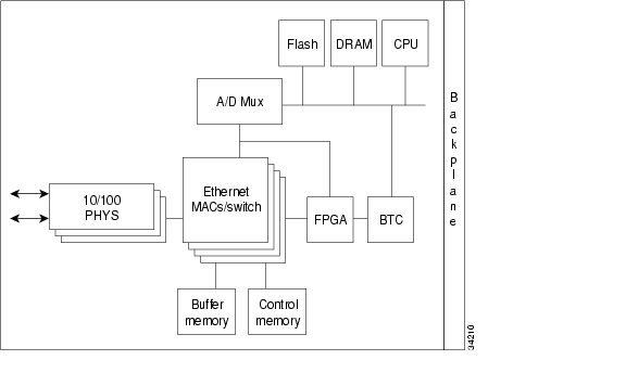
The E100T-G card provides twelve ports of IEEE 802.3-compliant, 10/100 interfaces. Each interface supports full-duplex operation for a maximum bandwidth of 200 MBit/s (Mbps) per port and 2.488 GBits/s (Gbps) per card. Each port independently detects the speed of an attached device (auto-senses) and automatically connects at the appropriate speed. The ports auto-configure to operate at either half or full duplex and can determine whether to enable or disable flow control. Figure 3-47 shows the card faceplate and Figure 3-48 shows a block diagram of the card.
Figure 3-47 E100T-G faceplate
Figure 3-48 E100T-G block diagram
The E100T-G Ethernet card provides high-throughput, low-latency packet switching of Ethernet traffic across an SDH/SONET network while providing a greater degree of reliability through SDH/SONET "self-healing" protection services. This Ethernet capability enables network operators to provide multiple 10/100 MBit/s (Mbps) access drops for high-capacity customer LAN interconnects, Internet traffic, and cable modem traffic aggregation. Efficient transport and co-existence of traditional TDM traffic with packet-switched data traffic are provided.
The E100T-G eliminates the need for external aggregation equipment such as Ethernet switches, remote headends or distributed points of presence (POPs).
Each E100T-G card supports standards-based, wire-speed, Layer 2 Ethernet switching between its Ethernet ports. The 802.1Q tag and port-based VLANs logically isolate traffic (typically subscribers). Priority queuing is also supported to provide multiple classes of service.
You can install the E100T-G card in any multispeed slot. Multiple Ethernet cards installed in an ONS 15454 SDH act as a single switch supporting a variety of SDH/SONET port configurations. You can create logical SDH/SONET ports by provisioning a number of VC-4 channels to the packet switch entity within the ADM. Logical ports can be created with a bandwidth granularity of VC-4. The ONS 15454 SDH supports VC-4-1c, VC-4-2c, or VC-4-4c signal levels.
3.28.1 E100T-G Card-Level Indicators
The E100T-G card faceplate has two card-level LED indicators, listed in Table 3-25.
3.28.2 E100T-G Port-Level Indicators
The E100T-G card also has twelve pairs of LEDs (one pair for each port) to indicate port conditions. A green L LED indicates that a link is detected. A yellow A LED indicates an active connection. If the A LED is off it indicates an inactive connection or unidirectional traffic. The port-level indicators are described in Table 3-26.
You can find the status of the E100T-G card port using the LCD screen on the ONS 15454 SDH fan-tray assembly. Use the LCD to view the status of any port or card slot; the screen displays the number and severity of alarms for a given port or slot. Refer to Chapter 1, "Alarm Troubleshooting," for a complete description of the alarm messages.
3.28.3 E100T-G Card Specifications
•
–
–
–
•
–
–
–
–
–
•
ONS 15454 SDH cards, when installed in a system, comply with these standards:
–
3.29 E1000-2-G Card
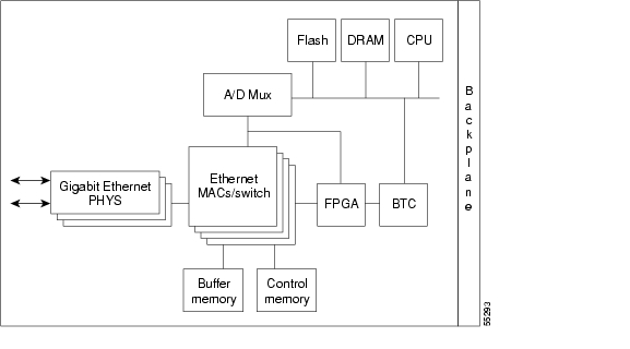
The E1000-2-G card provides two ports of IEEE-compliant, 1000 MBit/s (Mbps) interfaces. Each interface supports full-duplex operation for a maximum bandwidth of 2 GBits/s (Gbps) per port and 4 GBits/s (Gbps) per card. Each port auto-configures for full duplex and IEEE 802.3x flow control. The E1000-2-G card uses GBIC modular receptacles for the optical interfaces.
Two GBIC modules are offered as separate orderable products for maximum customer flexibility: an IEEE 1000Base-SX compliant, 850-nm optical module and an IEEE 1000Base-LX-compliant, 1300-nm optical module. The 850-nm SX optics are designed for multimode fiber and distances of up to 220 meters on 62.5 micron fiber and up to 550 meters on 50 micron fiber. The 1300-nm LX optics are designed for single-mode fiber and distances of up to five kilometers. Other GBIC modules for long-reach 1550-nm and twisted-pair copper will be offered for use with the E1000 card in a future release. Figure 3-49 shows the card faceplate and Figure 3-50 shows a block diagram of the card.
Note
Warning
Figure 3-49 E1000-2-G faceplate
Figure 3-50 E1000-2-G block diagram
Warning
The E1000-2-G Gigabit Ethernet card provides high-throughput, low-latency packet switching of Ethernet encapsulated traffic (IP and other Layer 3 protocols) across an SDH/SONET network while providing a greater degree of reliability through SDH/SONET "self-healing" protection services. This enables network operators to provide multiple 1000 MBit/s (Mbps) access drops for high-capacity customer LAN interconnects, Internet traffic, and cable modem traffic aggregation. Efficient transport and co-existence of traditional TDM traffic with packet-switched data traffic is provided.
The E1000-2-G card eliminates the need for external aggregation equipment such as Ethernet or ATM switches at the customer site, remote headends or distributed POPs.
Each E1000-2-G card supports standards-based, Layer 2 Ethernet switching between its Ethernet ports and any other Ethernet or SDH/SONET trunk interfaces on the ONS 15454 SDH. The IEEE 802.1Q tag and port-based VLANS logically isolate traffic (typically subscribers). Priority queuing is also supported to provide multiple classes of service. Two queues are provided on card. Queue level is settable from 0 to 7; 0 to 3 and 4 to 7 map.
You can install the E1000-2-G card into any multispeed slot for a total shelf capacity of 20 Gigabit Ethernet ports. Multiple Ethernet cards installed in an ONS 15454 SDH can act as either a single switching entity or as a single switch supporting a variety of SDH/SONET port configurations.
You can create logical SDH/SONET ports by provisioning VC channels to the packet switch entity within an ADM. Logical ports can be created with a bandwidth granularity of VC-4. In a single or multicard configuration, the ONS 15454 SDH can support 1 VC-4-4c, 2 VC-4-2c, or 4 VC-4-1c unstitched VC signal levels and 2 VC-4-2c or 4 VC-4-1c stitched signal levels.
3.29.1 E1000-2-G Card-Level Indicators
The E1000-2-G card faceplate has two card-level LED indicators, listed in Table 3-27.
3.29.2 E1000-2-G Port-Level Indicators
The E1000-2-G card also has one bicolor LED per port. When the green LINK LED is on, the linkbeat is detected, meaning an active network cable is installed. When the green LINK LED is off, an active network cable is not plugged into the port. The amber port ACT LED flashes at a rate proportional to the level of traffic being received and transmitted over the port.
3.29.3 E1000-2-G Card Specifications
•
–
–
–
•
–
–
–
–
–
•
ONS 15454 SDH optical cards, when installed in a system, comply with these standards:
–
–
3.30 G1000-4 Card
The G1000-4 card provides four ports of IEEE-compliant, 1000 MBit/s (Mbps) interfaces. Each interface supports full-duplex operation for a maximum bandwidth of 1 GBits/s (Gbps) or 2 GBits/s (Gbps) bidirectional per port, and 2.5 GBits/s (Gbps) or 5 GBits/s (Gbps) bidirectional per card. Each port auto-negotiates for full duplex and 802.3x flow control. The G1000-4 card uses GBIC modular receptacles for the optical interfaces.
Cisco offers three GBIC modules as separate orderable products for maximum flexibility:
•
•
•
The 850-nm SX optics are designed for multimode fiber and distances of up to 220 meters on 62.5 micron fiber and up to 550 meters on 50 micron fiber. The 1300-nm LX optics are designed for single-mode fiber and distances of up to ten kilometers. The 1550-nm ZX optics are designed for single-mode fiber and distances of up to eighty kilometers. Figure 3-51 shows the card faceplate and the block diagram of the card.
Note
Warning
Figure 3-51 G1000-4 faceplate and block diagram
Warning
The G1000-4 Gigabit Ethernet card provides high-throughput, low-latency transport of Ethernet encapsulated traffic (IP and other Layer 2 or Layer 3 protocols) across an SDH/SONET network while providing a greater degree of reliability through SDH/SONET "self-healing" protection services. Carrier-class Ethernet transport is achieved by hitless (< 50 ms) performance in the event of any failures or protection switches (such as 1+1 MSP, SNCP, MS-SPRing, or optical equipment protection) and full provisionability and manageability, as in SONET service. Full provisioning support is possible via CTC or CTM.
You can install the G1000-4 card into any multispeed slot for a total shelf capacity of 48 Gigabit Ethernet ports. (The practical limit is 40 ports because at least two slots are typically populated by optical cards such as STM-64). Each G1000-4 card performs completely independently of the other cards in the same shelf.
You can create logical SDH/SONET ports by provisioning VC channels to the packet switch entity within an ADM. Logical ports can be created with a bandwidth granularity of VC-4. In a single or multicard configuration, the ONS 15454 SDH can support 1 VC-4-4c, 2 VC-4-2c, or 4 VC-4-1c unstitched VC signal levels and 2 VC-4-2c or 4 VC-4-1c stitched signal levels. Each Ethernet port can be mapped to exactly one SONET/SDH circuit creating a logical end-to-end Ethernet link over SONET/SDH. The SONET circuit sizes supported are STS-1, STS-3c, STS-6c, STS-9c, STS-24c, and STS-48c.
3.30.1 G1000-4 Card-Level Indicators
The G1000-4 card faceplate has two card-level LED indicators, listed in Table 3-28.
3.30.2 G1000-4 Port-Level Indicators
The G1000-4 card also has one bicolor LED per port. The function of these four LEDs is according to Table 3-29.
3.30.3 G1000-4 Card Specifications
•
–
–
–
•
–
–
–
–
–
•
ONS 15454 SDH optical cards, when installed in a system, comply with these standards:
–
–
![]()
![]()
![]()
![]()
![]()
![]()
![]()
![]()
Posted: Sat Sep 24 13:53:05 PDT 2005
All contents are Copyright © 1992--2005 Cisco Systems, Inc. All rights reserved.
Important Notices and Privacy Statement.