cc/td/doc/product/ong/15400/r80docs
hometocprevnextglossaryfeedbacksearchhelp
PDF

Table Of Contents

Performance Monitoring

17.1  Threshold Performance Monitoring

17.2  Transponder and Muxponder Card Performance Monitoring

17.2.1  Optics PM Window

17.2.2  Payload PM Window

17.2.3  OTN PM Window

17.2.4  Ether Ports PM Window

17.3  DWDM Card Performance Monitoring

17.3.1  Optical Amplifier Card Performance Monitoring Parameters

17.3.2  Multiplexer and Demultiplexer Card Performance Monitoring Parameters

17.3.3  4MD-xx.x Card Performance Monitoring Parameters

17.3.4  OADM Channel Filter Card Performance Monitoring Parameters

17.3.5  OADM Band Filter Card Performance Monitoring Parameters

17.3.6  Optical Service Channel Card Performance Monitoring Parameters

17.4  Optics and 8b10b PM Parameter Definitions

17.5  ITU G.709 and ITU-T G.8021 Trunk-Side PM Parameter Definitions

17.6  Full RMON Statistics PM Parameter Definitions

17.7  FEC PM Parameter Definitions

17.8  SONET PM Parameter Definitions

17.9  SDH PM Parameter Definitions

17.10  Pointer Justification Count Performance Monitoring


Performance Monitoring


Performance monitoring (PM) parameters are used by service providers to gather, store, set thresholds for, and report performance data for early detection of problems. In this chapter, PM parameters and concepts are defined for transponder, muxponder, and dense wavelength division multiplexing (DWDM) cards in the Cisco ONS 15454 including optical amplifier, multiplexer, demutiplexer, optical add/drop multiplexer (OADM), and optical service channel (OSC) cards.


Note Unless otherwise specified, "ONS 15454" refers to both ANSI and ETSI shelf assemblies.


For information about enabling and viewing PM values, refer to the Cisco ONS 15454 DWDM Procedure Guide.

Chapter topics include:

Threshold Performance Monitoring

Transponder and Muxponder Card Performance Monitoring

DWDM Card Performance Monitoring

Optics and 8b10b PM Parameter Definitions

ITU G.709 and ITU-T G.8021 Trunk-Side PM Parameter Definitions

Full RMON Statistics PM Parameter Definitions

FEC PM Parameter Definitions

SONET PM Parameter Definitions

SDH PM Parameter Definitions

Pointer Justification Count Performance Monitoring


Note For additional information regarding PM parameters, refer to ITU G.826, ITU-T G.8021, ITU G.709, Telcordia documents GR-1230-CORE, GR-820-CORE, GR-499-CORE, and GR-253-CORE, and the ANSI T1.231 document entitled Digital Hierarchy - Layer 1 In-Service Digital Transmission Performance Monitoring.


17.1  Threshold Performance Monitoring

Thresholds are used to set error levels for each PM parameter. You can set individual PM threshold values from the Cisco Transport Controller (CTC) card view Provisioning tab. For procedures about provisioning card thresholds, such as line and path thresholds, refer to the Cisco ONS 15454 DWDM Procedure Guide.

During the accumulation cycle, if the current value of a PM parameter reaches or exceeds its corresponding threshold value, a threshold crossing alert (TCA) is generated by the node and is displayed by CTC. TCAs provide early detection of performance degradation. When a threshold is crossed, the node continues to count the errors during a given accumulation period. If zero is entered as the threshold value, generation of TCAs is disabled but performance monitoring continues.


Note Due to memory limitations and the number of TCAs generated by different platforms, you can manually add or modify the following two properties to the platform property file (CTC.INI for Windows and .ctcrc for UNIX) to fit the need:

ctc.15xxx.node.tr.lowater=yyy (where xxx is platform and yyy is the number of the lowater mark. The default lowater mark is 25.)

ctc.15xxx.node.tr.hiwater=yyy (where xxx is platform and yyy is the number of the hiwater mark. The default hiwater mark is 50.)

If the number of the incoming TCA is greater than the hiwater mark, the node will keep the latest lowater mark and discard older ones.


Change the threshold if the default value does not satisfy your error monitoring needs. For example, customers with a critical OC192/STM64 transponder installed for 911 calls must guarantee the best quality of service on the line; therefore, they lower all thresholds on the client side so that the slightest error raises a TCA.


Note When LOS, LOS-P, or LOF alarms occur on TXP and MXP trunks, ITU-T G.709/SONET/SDH TCAs are suppressed. For details, see "Alarm and TCA Monitoring and Management."


17.2  Transponder and Muxponder Card Performance Monitoring

This section lists PM parameters for transponder cards (TXP_MR_10G, TXP_MR_2.5G, TXPP_MR_2.5G, TXP_MR_10E, TXP_MR_10E_C, and TXP_MR_10E_L), muxponder cards (MXP_2.5G_10G, MXP_2.5G_10E, MXP_2.5G_10E_C, MXP_2.5G_10E_L, MXP_MR_2.5G, MXPP_MR_2.5G, MXP_MR_10DME-C, and MXP_MR_10DME-L), GE_XP, 10GE_XP, and ADM-10G cards. The transponder and muxponder PM parameters are divided into Optics PM, Payload PM, and OTN PM tabs. The tabs displayed vary depending on the card installed. For more information, see the "Optics PM Window" section, the "Payload PM Window" section, or the "OTN PM Window" section.

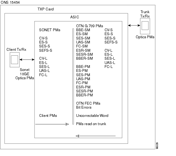
For ONS 15454 ANSI nodes, Figure 17-1 shows where overhead bytes detected on the application-specific integrated circuits (ASICs) produce PM parameters for the TXP_MR_10G card. The remaining transponder and muxponder cards perform similarly to this illustration.

Figure 17-1 ONS 15454 ANSI Node PM Read Points for TXP_MR_10G Card

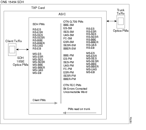
For ONS 15454 ETSI nodes, Figure 17-2 shows where overhead bytes detected on the ASICs produce PM parameters for the TXP_MR_10G card. The remaining transponder and muxponder cards perform similarly to this illustration.

Figure 17-2 ONS 15454 ETSI Node PM Read Points on TXP_MR_10G Cards

17.2.1  Optics PM Window

The Optics PM window lists parameters at the trunk and client side for all transponder, muxponder, GE_XP and 10GE_XP cards. The Optics PM window provides buttons to change the statistical values shown. The Refresh button manually refreshes statistics. Auto-Refresh sets a time interval at which automatic refresh occurs. In the Historical PM subtab, the Clear button sets the values on the card to zero. All counters on the card are cleared. The Help button activates context sensitive help. Table 17-1 lists the trunk-side and client-side optics PM parameters.

Table 17-1 Trunk-Side and Client-Side Optics PM Parameters 

Trunk-Side/Client-Side Optics PM Parameters
Definition

Laser Bias (Avg,%)

Average Laser Bias Current (Laser Bias Avg) is the average percentage of laser bias current during the PM time interval.

Laser Bias (Max,%)

Maximum Laser Bias Current (Laser Bias Max) is the maximum percentage of laser bias current during the PM time interval.

Laser Bias (Min,%)

Minimum Laser Bias Current (Laser Bias Min) is the minimum percentage of laser bias current during the PM time interval.

Link Status

Indicates if the Fibre Channel link is receiving a valid Fibre Channel signal (carrier) from the attached Fibre Channel device. Up means present, and down means not present.

Rx Optical Pwr (Min,dBm)

Minimum Receive Optical Power (Rx Optical Pwr Min, dBm) is the minimum received optical power during the PM time interval.

Rx Optical Pwr (Avg,dBm)

Average Receive Optical Power (Rx Optical Pwr Avg, dBm) is the average received optical power during the PM time interval.

Rx Optical Pwr (Max,dBm)

Maximum Receive Optical Power (Rx Optical Pwr Max, dBm) is the maximum received optical power during the PM time interval.

Tx Optical Pwr (Min,dBm)1

Minimum Transmit Optical Power (Tx Optical Pwr Min, dBm) is the minimum optical power transmitted during the PM time interval.

Tx Optical Pwr (Avg,dBm) 1

Average Transmit Optical Power (Tx Optical Pwr Avg, dBm) is the average optical power transmitted during the PM time interval.

Tx Optical Pwr (Max,dBm) 1

Maximum Transmit Optical Power (Tx Optical Pwr Max, dBm) is the maximum optical power transmitted during the PM time interval.

1 On the trunk side, this PM is not available for the following cards: TXP_MR_2.5G, TXPP_MR_2.5G, MXP_MR_2.5G, and MXPP_MR_2.5G.


17.2.2  Payload PM Window

The Payload PM window subtabs change depending on the card provisioning. For more information about provisioning TXP and MXP cards, refer to the "Provision Transponder and Muxponder Cards" chapter in the Cisco ONS 15454 DWDM Procedure Guide. Possible Payload PM subtabs are: SONET, SDH, Statistics, Utilization, and History. The following buttons function the same on all of the tabs. Not all tabs have all of these buttons.

The Refresh button manually refreshes statistics.

Auto-Refresh sets a time interval at which automatic refresh occurs.

The Baseline button resets the displayed statistics values to zero.

(Statistics window only) The Clear button allows you to set the values to zero for displayed statistics, all statistics for a port, and all statistics for all optical ports on a card.

The Help button activates context sensitive help.

For a list of the payload PM provisioning options for all transponder and muxponder cards, refer to the Cisco ONS 15454 DWDM Procedure Guide. The options selected in the Provisioning tab can affect the parameters displayed in the Performance > Payload PM tab.

Table 17-2 lists the PM parameter types that appear when a particular port type is provisioned for a transponder or muxponder card.

Table 17-2 Transponder and Muxponder Port Type PM Provisioning Options 

If this Port Type is Provisioned1
The Following PM Types are Activated2

SONET/SDH (including 10G Ethernet WAN Phy)
OC3/STM1
OC12/STM4
OC48/STM16

SONET or SDH PMs

10G Ethernet LAN Phy
10G FiberChannel
ONE_GE
FC1G
FC2G
FC1G ISL
FC2G ISL
FICON1G
FICON2G
FICON1G ISL
FICON2G ISL
ISC COMPAT
ISC PEER

Full remote monitoring (RMON) statistics

ESCON
DV6000
SDI_D1_VIDEO
HDTV
PASS_THRU
ETR_CLO

Payload PMs are not applicable to 2R port types.

1 The port type is provisioned from card view on the Provisioning > Pluggable Port Modules tab. For pluggable port module (PPM) provisioning procedures, refer to the Cisco ONS 15454 DWDM Procedure Guide.

2 Performance monitoring parameters are displayed from the card view on the Performance tab.


17.2.2.1  Payload PM SONET/SDH Window

Table 17-3 lists SONET/SDH layer near-end and far-end PM parameters listed in the card view on the Performance > Payload PM > SONET or SDH tab. SONET/SDH layer PMs are available when the client type is set to OC3/STM1, OC12/STM4, or OC48/STM16 on the TXP_MR_2.5G or when OC192/STM64 is set on the TXP_MR_10G, TXP_MR_10E, TXP_MR_10E_C, TXP_MR_10E_L, or ADM-10G on ONS 15454 SONET nodes. OC48/STM16 trunk PMs are available on MXP_MR_2.5G and MXPP_MR_2.5G cards on ONS 15454 SONET or ONS 15454 SDH nodes. OC48/STM16 client PMs are available on MXP_MR_10DME_C, MXP_MR_10DME_L, MXP_2.5G_10G, MXP_2.5G_10E, MXP_2.5G_10E_C, and MXP_2.5G_10E_L cards on ONS 15454 SONET or ONS 15454 SDH nodes. For PM definitions, see Table 17-29 and Table 17-30.

Table 17-3 ONS 15454 SONET/SDH Layer Far-End and Near-End PMs 

SONET

Layer Far-End (FE)1 , 2
Layer Near-End 1, 2
Note

CV-LFE
ES-LFE
FC-LFE
SES-LFE
UAS-LFE

CV-L
CV-S
ES-L
ES-S
FC-L
SES-L
SES-S
SEF-S
UAS-L

Applicable standard is Telcordia GR-253.

SDH

MS-BBE
MS-BBER
MS-EB
MS-ES
MS-ESR
MS-SES
MS-SESR
MS-UAS

RS-BBE
RS-BBER
RS-EB
RS-ES
RS-ESR
RS-SES
RS-SESR
RS-UAS
MS-BBE
MS-BBER
MS-EB
MS-ES
MS-ESR
MS-SES
MS-SESR
MS-UAS

Applicable standard is Telcordia GR-253.

1 Applicable to optical channel (OCH) and Client (CLNT) facilities.

2 For MXP_MR_2.5G and MXPP_MR_2.5G cards, these parameters are shown in the Performance > Payload PM > SONET PM tabs in the card view.


17.2.2.2  Payload PM Statistics Window

Table 17-4 lists the 10 Gigabit Ethernet (10 GE) payload statistics that are available on the TXP_MR_10G, TXP_MR_10E, TXP_MR_10E_C, and TXP_MR_10E_L cards. PPM provisioning must be completed under the card view Provisioning > Pluggable Port Modules tab for 10 GE to be enabled. For PPM provisioning procedures, refer to the Cisco ONS 15454 DWDM Procedure Guide. The parameters are listed under card view on the Performance > Payload PM > Statistics tab. For 10 GE payload definitions, see Table 17-27.


Note Utilization PMs are also available per port.


Table 17-4 Full RMON Statistics on TXP_MR_10G, TXP_MR_10E, TXP_MR_10E_C, TXP_MR_10E_L, GE_XP, and 10GE_XP cards 

Full RMON Statistics

dot3StatsFCSErrors
dot3StatsFrameTooLong
ifInBroadcastPkts
ifInErrors
ifInErrorsBytePkts
ifInFramingErrorPkts
ifInJunkInterPkts
ifInMulticastPkts
ifInOctets
ifOutBroadcastPkts
ifOutMulticastPkts
ifOutOctets
rxTotalPkts
Time Last Cleared
txTotalPkts

etherStatsBroadcastPkts
etherStatsCRCAlignErrors
etherStatsFragments
etherStatsJabbers
etherStatsMulticastPkts
etherStatsOctets
etherStatsOversizePkts
etherStatsPkts64Octets
etherStatsPkts65to127Octets
etherStatsPkts128to255Octets
etherStatsPkts256to511Octets
etherStatsPkts512to1023Octets
etherStatsPkts1024to1518Octets
etherStatsUndersizePkts
rxControlFrames
rxPauseFrames
rxUnknownOpcodeFrames


Table 17-5 lists the payload PM parameters that are available on the TXP_MR_2.5G and the TXPP_MR_2.5G cards when the ONE_GE or FC1G client type is enabled. For PPM provisioning procedures, refer to the Cisco ONS 15454 DWDM Procedure Guide. For payload definitions, see the "Optics and 8b10b PM Parameter Definitions" section and the "Full RMON Statistics PM Parameter Definitions" section.


Note Payload PM is not available for the 2FC client type.


Table 17-5 Gigabit Ethernet (GE) or Fibre Channel (FC) Payload PMs for the TXP_MR_2.5G and TXPP_MR_2.5G Cards 

GE or FC Payload Performance Parameters

8b/10bDataOrderedSets
8b/10bIdleOrderedSets
8b/10bNonIdleOrderedSets
8b/10bStatsEncodingDispErrors
ifInErrors
rxTotalPkts


Table 17-6 lists the payload PM parameters that are available on the MXP_MR_2.5G and the MXPP_MR_2.5G cards when the ONE_GE or the FC1G client type is enabled. For PPM provisioning procedures, refer to the Cisco ONS 15454 DWDM Procedure Guide. For payload definitions, see the "Optics and 8b10b PM Parameter Definitions" section and the "Full RMON Statistics PM Parameter Definitions" section.

Table 17-6 ONE_GE or FC1G Payload PMs for the MXP_MR_2.5G and MXPP_MR_2.5G Cards 

ONE_GE or FC1G Payload Performance Parameters

8b10bInvalidOrderedSets
8b10bStatsEncodingDispErrors
ifInDiscards
ifInErrors
ifInOctets
ifOutDiscards
ifOutOctets
mediaIndStatsRxFramesBadCRC
mediaIndStatsRxFramesTooLong
mediaIndStatsRxFramesTruncated
mediaIndStatsTxFramesBadCRC
rxTotalPkts
txTotalPkts


Table 17-7 lists the FC client-side payload PM parameters. FC payload PMs are available on the FC port on both the MXP_MR_2.5G and the MXPP_MR_2.5G cards when the FC1G client type is enabled. For PPM provisioning procedures, refer to the Cisco ONS 15454 DWDM Procedure Guide. For payload definitions, see the "Full RMON Statistics PM Parameter Definitions" section.

Table 17-7 FC1G Payload PMs on the Client Side 

FC1G Payload PMs on the Client Port

fcStatsLinkRecoveries
fcStatsRxCredits
fcStatsTxCredits
fcStatsZeroTxCredits
gfpStatsRoundTripLatencyUSec
gfpStatsRxDistanceExtBuffers
gfpStatsTxDistanceExtBuffers


Table 17-8 lists the Transparent Generic Framing Procedure (GFP-T) payload PMs. The GFP-T payload PMs are available on the GFP port on both the MXP_MR_2.5G and the MXPP_MR_2.5G cards when the ONE_GE or the 1 FC client type is enabled. GFP-T payload PMs are also available on the client port on both the MXP_MR_2.5G and the MXPP_MR_2.5G cards when the 1 FC client type is enabled. For PPM provisioning procedures, refer to the Cisco ONS 15454 DWDM Procedure Guide. For payload definitions, see the "Full RMON Statistics PM Parameter Definitions" section.

Table 17-8 GFP-T Payload PMs 

GFP-T Payload PMs on the GFP Port

gfpStatsCSFRaised
gfpStatsLFDRaised
gfpStatsRxCRCErrors
gfpStatsRxMBitErrors
gfpStatsRxSBitErrors
gfpStatsRxTypeInvalid


17.2.2.3  MXP_MR_2.5G/MXPP_MR_2.5G Payload Utilization Window

The Payload PM Utilization window in the card view Performance > Payload> Utilization tab shows the percentage of transmit (Tx) and receive (Rx) line bandwidth used by the ports during consecutive time segments. This tab cannot be viewed unless the appropriate PPM port type is provisioned. For PPM provisioning procedures, refer to the Cisco ONS 15454 DWDM Procedure Guide. The Utilization window provides an Interval list that enables you to set time intervals of 15 minutes or 1 day. Line utilization is calculated with the following formulas:

Rx = (inOctets + inPkts * 20) * 8 / 100% interval * maxBaseRate

Tx = (outOctets + outPkts * 20) * 8 / 100% interval * maxBaseRate

The interval is defined in seconds. The maxBaseRate is defined by raw bits per second in one direction for the port (that is, 1 Gbps). The maxBaseRate for MXP_MR_2.5G and MXPP_MR_2.5G cards is shown for the ONS 15454 nodes in Table 17-9.

Table 17-9 maxBaseRate for STS and VC Circuits 

STS/VC
maxBaseRate

STS-1/VC3

51840000

STS-3c/VC4

155000000

STS-6c/VC4-2c

311000000

STS-12c/VC4-4c

622000000


Note Line utilization numbers express the average of ingress and egress traffic as a percentage of capacity.


17.2.2.4  Payload History Window

The Payload PM History window in the card view Performance > Payload > History tab lists past statistics for the previous time intervals. This tab cannot be viewed unless the appropriate PPM port type is provisioned. For PPM provisioning procedures, refer to the Cisco ONS 15454 DWDM Procedure Guide. Depending on the selected time interval, the History window displays the statistics for each port for the number of previous time intervals as shown in Table 17-10.

Table 17-10 History Statistics per Time Interval

Time Interval
Number of Intervals Displayed

15 minutes

32 (current and previous)

1 day (24 hours)

2 (current and previous)


17.2.3  OTN PM Window

The OTN tab has an ITU-T G.709 PM subtab and an FEC PM subtab. Both subtabs provide buttons to change the statistical values shown in the Performance tab. The Refresh button manually refreshes statistics. Auto-Refresh sets a time interval at which automatic refresh occurs. The Baseline button resets the displayed statistics values to zero. The Statistics window also has a Clear button. The Clear button sets the values on the card to zero. All counters on the card are cleared. The Help button activates context sensitive help. For more information about provisioning optical transport network (OTN) settings, refer to the Cisco ONS 15454 DWDM Procedure Guide.

Table 17-11 lists the OTN PM provisioning options for all transponder, muxponder, GE_XP, and 10GE_XP cards. The options selected in the Provisioning tab affects the parameters displayed in the Performance > OTN PM tab.

Table 17-11 Transponder and Muxponder PM Provisioning Options 

Card
OTN Provisioning1

MXPP_MR_2.5G

MXP_2.5G_10E

G.709
FEC
FEC Thresholds

MXP_2.5G_10E_C

G.709
FEC
FEC Thresholds

MXP_2.5G_10E_L

G.709
FEC
FEC Thresholds

MXP_2.5G_10G

G.709
FEC
FEC Thresholds

MXP_MR_2.5G

MXP_MR_10DME_C

G.709
FEC
FEC Thresholds

MXP_MR_10DME_L

G.709
FEC
FEC Thresholds

TXPP_MR_2.5G

G.709
FEC
FEC Thresholds

TXP_MR_10E

G.709
FEC
FEC Thresholds

TXP_MR_10E_C

G.709
FEC
FEC Thresholds

TXP_MR_10E_L

G.709
FEC
FEC Thresholds

TXP_MR_10G

G.709
FEC
FEC Thresholds

TXP_MR_2.5G

G.709
FEC
FEC Thresholds

ADM-10G

G.709
FEC
FEC Thresholds

GE_XP

G.709
FEC
FEC Thresholds

10GE_XP

G.709
FEC
FEC Thresholds

1 OTN provisioning is performed from card view on the Provisioning > OTN > OTN Lines, G.709 Thresholds, and FEC Thresholds tabs.


Table 17-12 lists the OTN trunk-side PM parameters listed on the G.709 tab. OTN PMs are available when ITU G.709 is enabled from the card view Provisioning > OTN > OTN Lines tab. OTN PMs are not available on MXP_MR_2.5G and MXPP_MR_2.5G cards. For ITU G.709 section and path monitoring PM definitions, see the "ITU G.709 and ITU-T G.8021 Trunk-Side PM Parameter Definitions" section.

Table 17-12 ITU G.709 OTN Trunk-Side PMs 

OTN Layer (Near End and Far End)1
Note

BBE-SM
BBER-SM
ES-SM
ESR-SM
FC-SM
SES-SM
SESR-SM
UAS-SM
FC-SM

ITU G.709 standard section monitoring
ITU-T G.8021

BBE-PM
BBER-PM
ES-PM
ESR-PM
FC-PM
SES-PM
SESR-PM
UAS-PM

ITU G.709 standard path monitoring
ITU-T G.8021

1 Applicable to OCH facility.


Table 17-13 lists the forward error correction (FEC) PM parameters. FEC PMs are available when ITU-T G.709 is enabled and FEC is set to standard or enhanced. These parameters are provisioned from the card view Provisioning > OTN > OTN Lines tab. FEC PMs are not available on MXP_MR_2.5G and MXPP_MR_2.5G cards. For PM definitions, see the "FEC PM Parameter Definitions" section.

Table 17-13 FEC OTN Trunk-Side PMs 

FEC Trunk-Side PMs
FEC (Near End)1

Bit Errors

BIEC

Uncorrectable Words

UNC-WORDS

1 Applicable to OCH facility.


Table 17-14 lists ONS 15454 optics and 8b10b PM parameters. For ONS 15454 optics and 8b10b definitions, see the "Optics and 8b10b PM Parameter Definitions" section.

Table 17-14 ONS 15454 Optics and 8b10b PMs 

Optics (Near End)1
8B10B (Near End)2

LBCL-AVG
LBCL-MAX
LBCL-MIN
OPT-AVG
OPT-MAX
OPT-MIN
OPR-AVG
OPR-MAX
OPR-MIN

CGV
DCG
IOS
IPC
NIOS
VPC

1 The TXP_MR_2.5G and TXPP_MR_2.5G card Enterprise System Connection (ESCON) payload does not support optics PMs on the client port due to Small Form-factor Pluggable (SFP)-imposed restrictions.

2 Applicable to TXP_MR_2.5G and TXPP_MR_2.5G cards only.


17.2.4  Ether Ports PM Window

CTC provides Ethernet port performance information, including line-level parameters, port bandwidth consumption, and historical Ethernet statistics. The Ethernet performance information is divided into the Statistics, Utilization, and History tabbed windows within the card view Performance tab window. For more information about provisioning ether ports, refer to the Cisco ONS 15454 DWDM Procedure Guide.

17.2.4.1  Ether Port Statistics Window

The Ethernet Statistics window lists Ethernet parameters at the line level. The Statistics window provides buttons to change the statistical values shown. The Baseline button resets the displayed statistics values to zero. The Refresh button manually refreshes statistics. Auto-Refresh sets a time interval at which automatic refresh occurs.

Table 17-15 defines the Ethernet Port statistics parameters.

Table 17-15 E-Series Ethernet Statistics Parameters 

Parameter
Definition

Time Last Cleared

A time stamp indicating the last time statistics were reset.

ifInOctets

Number of bytes received since the last counter reset.

rxTotalPkts

Number of received packets.

ifInUcastPkts

Number of unicast packets received since the last counter reset.

ifInMulticastPkts

Number of multicast packets received since the last counter reset.

ifInDiscards

The number of inbound packets that were chosen to be discarded even though no errors had been detected to prevent their being deliverable to a higher-layer protocol. One possible reason for discarding such a packet could be to free buffer space.

ifOutOctets

Number of bytes transmitted since the last counter reset.

txTotalPkts

Number of transmitted packets.

ifOutMulticastPkts

Number of multicast packets transmitted.

ifOutBroadcastPkts

Number of broadcast packets transmitted.

ifOutDiscards

Number of outbound packets which were chosen to be discarded even though no errors had been detected to prevent their transmission. A possible reason for discarding such packets could be to free up buffer space.

ifOurErrors

Number of outbound packets or transmission units that could not be transmitted because of errors.

dot3StatsAlignmentErrors

A count of frames received on a particular interface that are not an integral number of octets in length and do not pass the FCS check.

dot3StatsFCSErrors

A count of frames received on a particular interface that are an integral number of octets in length but do not pass the FCS check.

dot3StatsFrameTooLong

A count of frames received on a particular interface that exceed the maximum permitted frame size.

etherStatsUndersizePkts

The total number of packets received that were less than 64 octets long (excluding framing bits, but including FCS octets) and were otherwise well formed.

etherStatsFragments

The total number of packets received that were less than 64 octets in length (excluding framing bits but including FCS octets) and had either a bad FCS with an integral number of octets (FCS Error) or a bad FCS with a nonintegral number of octets (Alignment Error).


Note It is entirely normal for etherStatsFragments to increment. This is because it counts both runts (which are normal occurrences due to collisions) and noise hits.


etherStatsPkts64Octets

The total number of packets (including bad packets) received that were 64 octets in length (excluding framing bits but including FCS octets).

etherStatsPkts65to127Octets

The total number of packets (including bad packets) received that were between 65 and 127 octets in length inclusive (excluding framing bits but including FCS octets).

etherStatsPkts128to255Octets

The total number of packets (including bad packets) received that were between 128 and 255 octets in length inclusive (excluding framing bits but including FCS octets).

etherStatsPkts256to511Octets

The total number of packets (including bad packets) received that were between 256 and 511 octets in length inclusive (excluding framing bits but including FCS octets).

etherStatsPkts512to1023Octets

The total number of packets (including bad packets) received that were between 512 and 1023 octets in length inclusive (excluding framing bits but including FCS octets).

etherStatsPkts1024to1518Octets

The total number of packets (including bad packets) received that were between 1024 and 1518 octets in length inclusive (excluding framing bits but including FCS octets).

etherStatsBroadcastPkts

The total number of good packets received that were directed to the broadcast address. Note that this does not include multicast packets.

etherStatsMulticastPkts

The total number of good packets received that were directed to a multicast address. Note that this number does not include packets directed to the broadcast address.

etherStatsOversizePkts

The total number of packets received that were longer than 1518 octets (excluding framing bits, but including FCS octets) and were otherwise well formed. Note that for tagged interfaces, this number becomes 1522 bytes.

etherStatsJabbers

The total number of packets received that were longer than 1518 octets (excluding framing bits, but including FCS octets), and had either a bad FCS with an integral number of octets (FCS Error) or a bad FCS with a nonintegral number of octets (Alignment Error).

etherStatsOctets

The total number of octets of data (including those in bad packets) received on the network (excluding framing bits but including FCS octets.

etherStatsCRCAlignErrors

The total number of packets received that had a length (excluding framing bits, but including FCS octets) of between 64 and 1518 octets, inclusive, but had either a bad FCS with an integral number of octets (FCS Error) or a bad FCS with a nonintegral number of octets (Alignment Error).


17.2.4.2  Ether Ports Utilization Window

The Utilization window shows the percentage of transmit (Tx) and receive (Rx) line bandwidth used by the Ethernet ports during consecutive time segments. The Mode field displays the real-time mode status, such as 100 Full, which is the mode setting configured on the E-Series port. However, if the E-Series port is set to autonegotiate the mode (Auto), this field shows the result of the link negotiation between the E-Series and the peer Ethernet device attached directly to the E-Series port.

The Utilization window provides an Interval drop-down list that enables you to set time intervals of 1 minute, 15 minutes, 1 hour, and 1 day. Line utilization is calculated with the following formulas:

Rx = (inOctets + inPkts * 20) * 8 / 100% interval * maxBaseRate

Tx = (outOctets + outPkts * 20) * 8 / 100% interval * maxBaseRate

The interval is defined in seconds. The maxBaseRate is defined by raw bits per second in one direction for the Ethernet port (that is, 1 Gbps).

17.2.4.3  Ether Ports History Window

The Ether Port History window lists past Ethernet statistics for the previous time intervals. Depending on the selected time interval, the History window displays the statistics for each port for the number of previous time intervals as shown in Table 17-16. The parameters are defined in Table 17-15.

Table 17-16 Ethernet History Statistics per Time Interval

Time Interval
Number of Previous Intervals Displayed

1 minute

60

15 minutes

32

1 hour

24

1 day (24 hours)

7


17.3  DWDM Card Performance Monitoring

The following sections define PM parameters and definitions for the ONS 15454 OPT-PRE, OPT-BST, OPT-BST-L, OPT-AMP-L, OPT-AMP-17-C, 32MUX-O, 32DMX-O, 32DMX, 32DMX-L, 40-WSS-C, 40-WXC-C, 40-DMX-C, 40-MUX-C, 4MD-xx.x, AD-1C-xx.x, AD-2C-xx.x, AD-4C-xx.x, AD-1B-xx.x, AD-4B-xx.x, OSCM, OSC-CSM, 32WSS, and 32WSS-LDWDM cards.

17.3.1  Optical Amplifier Card Performance Monitoring Parameters

The PM parameters for the OPT-PRE, OPT-AMP-L, OPT-AMP-17-C, OPT-BST, and OPT-BST-L cards are listed Table 17-17. For ONS 15454 optics definitions, see the "Optics and 8b10b PM Parameter Definitions" section.

Table 17-17 Optical PM Parameters for Optical Amplifier Cards

Optical Line
Optical Amplifier Line

OPT

OPR


17.3.2  Multiplexer and Demultiplexer Card Performance Monitoring Parameters

The PM parameters for the 32MUX-O, 32WSS, 32WSS-L, 32DMX, 32DMX-L, 32DMX-O, 40-WSS-C, 40-WXC-C, 40-DMX-C, and 40-MUX-C cards are listed in Table 17-18. For ONS 15454 optics definitions, see the "Optics and 8b10b PM Parameter Definitions" section.

Table 17-18 Optical PM Parameters for 2MUX-O, 32WSS, 32WSS-L, 32DMX, 32DMX-L, 32DMX-O, 40-WSS-C, 40-WXC-C, 40-DMX-C, and 40-MUX-C Cards 

Optical Channel
Optical Line

OPR

OPT


17.3.3  4MD-xx.x Card Performance Monitoring Parameters

The PM parameters for the 4MD-xx.x cards are listed in Table 17-19. For ONS 15454 optics definitions, see the "Optics and 8b10b PM Parameter Definitions" section.

Table 17-19 Optical PM Parameters for 4MD-xx.x Cards 

Optical Channel
Optical Band

OPR

OPT


17.3.4  OADM Channel Filter Card Performance Monitoring Parameters

The PM parameters for the AD-1C-xx.x, AD-2C-xx.x, and AD-4C-xx.x cards are listed in Table 17-20. For ONS 15454 optics definitions, see the "Optics and 8b10b PM Parameter Definitions" section.

Table 17-20 Optical PM Parameters for AD-1C-xx.x, AD-2C-xx.x, and AD-4C-xx.x Cards 

Optical Channel
Optical Line

OPR

OPT


17.3.5  OADM Band Filter Card Performance Monitoring Parameters

The PM parameters for the AD-1B-xx.x and AD-4B-xx.x cards are listed in Table 17-21. For ONS 15454 optics definitions, see the "Optics and 8b10b PM Parameter Definitions" section.

Table 17-21 Optical PM Parameters for AD-1B-xx.x and AD-4B-xx.x Cards 

Optical Line
Optical Band

OPR

OPT


17.3.6  Optical Service Channel Card Performance Monitoring Parameters

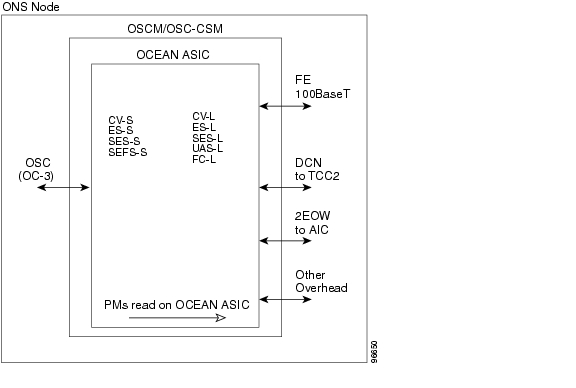
For ONS 15454 ANSI nodes, Figure 17-3 shows where overhead bytes detected on the ASICs produce PM parameters for the OSCM and OSC-CSM cards.

Figure 17-3 ONS 15454 ANSI Node PM Read Points on OSCM and OSC-CSM Cards

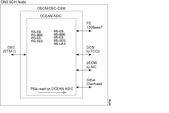
For ONS 15454 ETSI nodes, Figure 17-4 shows where overhead bytes detected on the ASICs produce PM parameters for the OSCM and OSC-CSM cards.

Figure 17-4 ONS 15454 ETSI Node PM Read Points on OSCM and OSC-CSM Cards

The ONS 15454 ANSI node PM parameters for the OSCM and OSC-CSM cards are listed in Table 17-22. For PM definitions, see the "SONET PM Parameter Definitions" section. For optics PM definitions, see the "Optics and 8b10b PM Parameter Definitions" section.

Table 17-22 ANSI OSCM/OSC-CSM (OC3) Card PMs 

Section (Near End)1
Line (Near End/Far End) 1
Optics (Near End)2

CV-S
ES-S
SEF-S
SES-S

CV-L
ES-L
FC-L
SES-L
UAS-L

OPWR

1 Applicable to OC3

2 Applicable to OTS facilities


Table 17-23 ETSI OSCM and OSC-CSM Card PMs 

Regeneration Section (Near End)
Multiplex Section (Near End/Far End)
Optics (Near End)

RS-BBE
RS-EB
RS-ES
RS-SES

MS-BBE
MS-EB
MS-ES
MS-SES
MS-UAS

OPT


17.4  Optics and 8b10b PM Parameter Definitions

Table 17-24 lists Cisco ONS 15454 optics and 8b10b PM parameter definitions.

Table 17-24 ONS 15454 Optics and 8b10b PM Definitions 

Parameter
Definition

8b10bDataOrderedSets

8b10b takes 8 bits of data and sends it as 10 bits, which allows control information to be sent along with the data. DataOrderedSets is a count of data ordered sets.

8b10bErrors

8b10b takes 8 bits of data and sends it as 10 bits, which allows control information to be sent along with the data. Errors is a count of 10b errors received by the serial or deserializer (serdes 8b/10b).

8b10bIdleOrderedSets

8b10b takes 8 bits of data and sends it as 10 bits, which allows control information to be sent along with the data. IdleOrderedSets is a count of idle ordered sets.

8b10bInvalidOrderedSets

8b10b takes 8 bits of data and sends it as 10 bits, which allows control information to be sent along with the data. InvalidOrderedSets is a count of the received invalid work errors.

8b10bNonIdleOrderedSets

8b10b takes 8 bits of data and sends it as 10 bits, which allows control information to be sent along with the data. NonIdleOrderedSets is a count of ordered sets that are not idle.

8b10bStatsEncodingDispErrors

8b10b takes 8 bits of data and sends it as 10 bits, which allows control information to be sent along with the data. StatsEncodingDispErrors is a count of the received disparity errors.

BIE

The number of bit errors (BIE) corrected in the DWDM trunk line during the PM time interval.

BIEC

The number of Bit Errors Corrected (BIEC) in the DWDM trunk line during the PM time interval.

CGV

Code Group Violations (CGV) is a count of received code groups that do not contain a start or end delimiter.

DCG

Date Code Groups (DCG) is a count of received data code groups that do not contain ordered sets.

IOS

Idle Ordered Sets (IOS) is a count of received packets containing idle ordered sets.

IPC

Invalid Packets (IPC) is the count of received packets that contain errored data code groups that have start and end delimiters.

LBCL-AVG

Laser Bias Current Line-Average (LBCL-AVG) is the average percentage of laser bias current.

LBCL-MAX

Laser Bias Current Line-Maximum (LBCL-MAX) is the maximum percentage of laser bias current.

LBCL-MIN

Laser Bias Current Line-Minimum (LBCL-MIN) is the minimum percentage of laser bias current.

LOFC

Loss of Frame Count (LOFC) is a count of the lost frames.

NIOS

Non-Idle Ordered Sets (NIOS) is a count of received packets containing non-idle ordered sets.

OPR

Optical Power Received (OPR) is the measure of average optical power received as a percentage of the nominal OPR.

OPR-AVG

Average Receive Optical Power (OPR-AVG) is the average received optical power measured in dBm.

OPR-MAX

Maximum Receive Optical Power (OPR-MAX) is the maximum received optical power measured in dBm.

OPR-MIN

Minimum Receive Optical Power (OPR-MIN) is the minimum received optical power measured in dBm.

OPT

Optical Power Transmitted (OPT) is the average optical power transmitted as a percentage of the nominal OPT.

OPT-AVG

Average Transmit Optical Power (OPT-AVG) is the average transmitted optical power measured in dBm.

OPT-MAX

Maximum Transmit Optical Power (OPT-MAX) is the maximum transmitted optical power measured in dBm.

OPT-MIN

Minimum Transmit Optical Power (OPT-MIN) is the minimum transmitted optical power measured in dBm.

OPWR-AVG

Optical Power - Average (OPWR-AVG) is the measure of average optical power on the unidirectional port.

OPWR-MAX

Optical Power - Maximum (OPWR-MAX) is the measure of maximum value of optical power on the unidirectional port.

OPWR-MIN

Optical Power - Minimum (OPWR-MIN) is the measure of minimum value of optical power on the unidirectional port.

UNC-WORDS

Uncorrectable Words (UNC-WORDS) is the number of uncorrectable words detected in the DWDM trunk line during the PM time interval.

VPC

Valid Packets (VPC) is a count of received packets that contain non-errored data code groups that have start and end delimiters.


17.5  ITU G.709 and ITU-T G.8021 Trunk-Side PM Parameter Definitions

Table 17-27 defines the ITU G.709 and ITU-T G.8021 section monitoring trunk-side PM parameters. For more information, see the "Transponder and Muxponder Card Performance Monitoring" section.

Table 17-25 ITU G.709 and ITU-T G.8021 Section Monitoring PM Definitions 

Parameter
Definition

BBE-SM

Section Monitoring Background Block Errors (BBE-SM) shows the number of background block errors recorded in the OTN section during the PM time interval.

BBER-SM

Section Monitoring Background Block Errors Ratio (BBER-SM) shows the background block errors ratio recorded in the OTN path during the PM time interval.

ES-SM

Section Monitoring Errored Seconds (ES-SM) shows the errored seconds recorded in the OTN section during the PM time interval.

ESR-SM

Section Monitoring Errored Seconds Ratio (ESR-SM) shows the severely errored seconds ratio recorded in the OTN section during the PM time interval.

FC-SM

Section Monitoring Failure Counts (FC-SM) shows the failure counts recorded in the OTN section during the PM time interval.

SES-SM

Section Monitoring Severely Errored Seconds (SES-SM) shows the severely errored seconds recorded in the OTN section during the PM time interval.

SESR-SM

Section Monitoring Severely Errored Seconds Ratio (SESR-SM) shows the severely errored seconds ratio recorded in the OTN section during the PM time interval.

UAS-SM

Section Monitoring Unavailable Seconds (UAS-SM) shows the unavailable seconds recorded in the OTN section during the PM time interval.


Table 17-26 defines the ITU G.709 path monitoring trunk-side PM parameters. For more information, see the "Transponder and Muxponder Card Performance Monitoring" section.

Table 17-26 ITU G.709 Path Monitoring PM Definitions 

Parameter
Definition

BBE-PM

Path Monitoring Background Block Errors (BBE-PM) shows the number of background block errors recorded in the OTN path during the PM time interval.

BBER-PM

Path Monitoring Background Block Errors Ratio (BBER-PM) shows the background block errors ratio recorded in the OTN path during the PM time interval.

ES-PM

Path Monitoring Errored Seconds (ES-PM) shows the errored seconds recorded in the OTN path during the PM time interval.

ESR-PM

Path Monitoring Errored Seconds Ratio (ESR-PM) shows the severely errored seconds ratio recorded in the OTN path during the PM time interval.

FC-PM

Path Monitoring Failure Counts (FC-PM) shows the failure counts recorded in the OTN path during the PM time interval.

SES-PM

Path Monitoring Severely Errored Seconds (SES-PM) shows the severely errored seconds recorded in the OTN path during the PM time interval.

SESR-PM

Path Monitoring Severely Errored Seconds Ratio (SESR-PM) shows the severely errored seconds ratio recorded in the OTN path during the PM time interval.

UAS-PM

Path Monitoring Unavailable Seconds (UAS-PM) shows the unavailable seconds recorded in the OTN path during the PM time interval.


17.6  Full RMON Statistics PM Parameter Definitions

Table 17-27 defines the MXP_MR_2.5G, MXPP_MR_2.5G, TXP_MR_10E, TXP_MR_10E_C, and TXP_MR_10E_L card full RMON statistics PM parameters. For more information, see the "Transponder and Muxponder Card Performance Monitoring" section.

Table 17-27 Full RMON Statistics PM Definitions 

Parameter
Definition

dot3StatsFCSErrors

The number of frames with frame check errors.

dot3StatsFrameTooLong

The number of packets at least 64 octets long, without a bad Frame Check Sequence (FCS), where the 802.3 length/type field did not match the computed DATA field length.

etherStatsBroadcastPkts

The number of broadcast packets, excluding multicast packets, that are 64-16376 octets in length, and have a valid FCS.

etherStatsCRCAlignErrors

The number of packets that are 64-1518 octets in length without an integral number of octets, or with a bad FCS.

etherStatsFragments

The number of packets less than 64 octets long that do not have an integral number of octets or that have a bad FCS.

etherStatsJabbers

The number of octets of data, including bad packets, that were received on the network.

etherStatsMulticastPkts

The number of multicast packets, excluding broadcast packets, that are 64-16376 octets in length, and have a valid FCS.

etherStatsOctets

The number in bytes of received packets, including bad packets and excluding framing bits except for FCS bytes.

etherStatsOversizePkts

The number of packets more than 16376 octets long that have a valid FCS.

etherStatsPkts64Octets

The number of packet received, including error packets, that are 64 octets in length.

etherStatsPkts65to127Octets

The number of packets received, including error packets, that are 65-127 octets in length.

etherStatsPkts128to255Octets

The number of packets received, including error packets, that are 128-255 octets in length.

etherStatsPkts256to511Octets

The number of packets received, including error packets, that are 256-511 octets in length.

etherStatsPkts512to1023Octets

The number of packets received, including error packets, that are 512-1023 octets in length.

etherStatsPkts1024to1518Octets

The number of packets received, including error packets, that are 1024-1518 octets in length.

etherStatsUndersizePkts

The number of packets less than 64 octets long that have a valid FCS.

fcStatsLinkRecoveries

The number of link recoveries.

fcStatsRxCredits

The number of current receive buffer to buffer credits.

fcStatsTxCredits

The number of current transmit buffer to buffer credits.

fcStatsZeroTxCredits

This is a count that increments when the FC/FICON Tx credits go from a nonzero value to zero.

gfpStatsLFDRaised

The number of loss of frame delineation (LFD) raised.

gfpStatsRoundTripLatencyUSec

Round trip delay for the end-to-end Fibre Channel transport in microseconds.

gfpStatsRxCRCErrors

The number of packets received with a payload FCS error.

gfpStatsRxCSFRaised

Received GFP loss of client character synchronization (LOCCS).

gfpStatsRxDistanceExtBuffers

The number of receive buffer credit for GFP-T (valid only if distance extension is enabled).

gfpStatsRxMBitErrors

The received multibit errored core header count (cHEC).

gfpStatsRxSBitErrors

The received single-bit errored cHEC.

gfpStatsRxSblkCRCErrors

The number of packets received with a payload FCS error. Sblk stands for super block in the GFP payload.

gfpStatsRxTypeInvalid

Received invalid type.

gfpStatsTxDistanceExtBuffers

The number of transmit buffer credit for GFP-T (valid only if distance extension is enabled).

ifInBroadcastPkts

The number of packets delivered to a higher sublayer and addressed to a broadcast address at this sublayer.

ifInDiscards

The number of inbound packets that were chosen to be discarded even though no errors were detected, to prevent them from being deliverable to a higher-layer protocol. One possible reason for discarding such a packet could be to free buffer space.

ifInErrors

The number of inbound packets (or transmission units) that contained errors preventing them from being delivered to a higher-layer protocol.

ifInErrorBytePkts

The number of received packets with an error symbol detected.

ifInFramingErrorPkts

The number of received packets with a control symbol other than an error detected.

ifInJunkInterPkts

The number of interpacket gaps between valid start symbols during which a symbol other than idle is detected, including packets of length 1-8 octets.

ifInMulticastPkts

The total number of multicast frames received error-free.

ifInOctets

The number of bytes received since the last counter reset.

ifOutBroadcastPkts

The number of packets requested by higher-level protocols and addressed to a broadcast address at this sublayer, including those not transmitted.

ifOutDiscards

The number of outbound packets that were chosen to be discarded even though no errors had been detected to prevent their being transmitted. One possible reason for discarding such a packet could be to free buffer space.

ifOutMulticastPkts

The number of multicast frames transmitted error-free.

ifOutOctets

The number of bytes transmitted since the last counter reset.

InvalidCRCError

A count of invalid cyclic redundancy checks (CRCs).

mediaIndStatsRxFramesBadCRC

The number of received frames with a CRC error.

mediaIndStatsRxFramesTooLong

The number of received frames that are too long.

mediaIndStatsRxFramesTruncated

The number of received frames that are too small.

mediaIndStatsTxFramesBadCRC

The number of transmitted frames with a CRC error.

Running Disparity Count

A count of errors that affect the disparity of the received data stream.

rxControlFrames

The number of MAC control packets that are type 0x8808 and contain at least 64 octets in length.

rxFrames

A count of the number of frames received without errors.

rxLinkReset (Only for FC Mode)

A count of the received link resets.

rxPauseFrames

The number of received 802.x paused frames.

rxTotalPkts

The number of received packets.

rxUnknownOpcodeFrames

Number of packets of at least 64 octets in length and type 0x8808, with opcode not equal to 1.

Time Last Cleared

A time stamp indicating the last time statistics were reset.

txBytes

A count of the number of bytes transmitted from the frame since the last counter reset.

txFrames

A count of the number of transmitted frames.

txTotalPkts

The number of transmitted packets.


17.7  FEC PM Parameter Definitions

Table 17-28 defines the MXP_MR_2.5G, MXPP_MR_2.5G, TXP_MR_10E, TXP_MR_10E_C, and TXP_MR_10E_L card FEC PM parameters. For more information, see the "Transponder and Muxponder Card Performance Monitoring" section.

Table 17-28 FEC PM Definitions 

Parameter
Definition

Bit Errors

Bit Errors are the number of bit errors corrected.

FEC (NE)

FEC enables correction and detection of errors along the optical links where OTN and FEC are provisioned. FEC uses Reed Solomon code RS (255,239) encoding. The FEC field is found in Rows 1 to 4 and Columns 3835 to 4080. It will contain either the Reed-Solomon RS(255,239) codes, or if FEC is disabled, fixed stuff bytes (zeros).

Note The FEC PM information can be found in the card view Performance > OTN PM tab. FEC must be enabled on the transponder units in order for FEC PM values to be reported.

UNC-Words

Uncorrectable Words (UNC-Words) occur when FEC detects and corrects errors to deliver a 7 to 8 dB improvement in the signal-to-noise ratio (also called margin). For ITU G.709, the FEC code used is Reed-Solomon RS (255, 239).


17.8  SONET PM Parameter Definitions

Table 17-29 gives definitions for each type of SONET PM parameter available on an ONS 15454 ANSI node. These parameters become available when the client type is set to OC-3, OC-12, or OC-48 on a TXP_MR_2.5G or TXPP_MR_2.5G card or to OC-192 on a TXP_MR_10G, TXP_MR_10E, TXP_MR_10E_C, or TXP_MR_10E_L card. The OC-48 client PM is available on MXP_2.5_10G, MXP_2.5G_10E, MXP_2.5G_10E_C, MXP_2.5G_10E_L, MXP_MR_10DME_C, and MXP_MR_10DME_L cards. The OC-48 trunk PM is available on MXP_MR_2.5G and MXPP_MR_2.5G cards.

Table 17-29 SONET PM Parameters 

Parameter
Definition

CV-L

Line Coding Violation (CV-L) indicates the number of coding violations occurring on the line. This parameter is a count of bipolar violations (BPVs) and excessive zeros (EXZs) occurring over the accumulation period.

CV-S

Section Coding Violation (CV-S) is a count of bit interleaved parity (BIP) errors detected at the section layer (that is, using the B1 byte in the incoming SONET signal). Up to eight section BIP errors can be detected per STS-N frame; each error increments the current CV-S second register.

ES-L

Line Errored Seconds (ES-L) is a count of the seconds containing one or more anomalies (BPV + EXZ) and/or defects (that is, loss of signal) on the line.

ES-S

Section Errored Seconds (ES-S) is a count of the number of seconds when at least one section-layer BIP error was detected or an SEF or loss of signal (LOS) defect was present.

FC-L

Line Failure Count (FC-L) is a count of the number of near-end line failure events. A failure event begins when an Alarm Indication Signal Line (AIS-L) failure is declared or when a lower-layer, traffic-related, near-end failure is declared. This failure event ends when the failure is cleared. A failure event that begins in one period and ends in another period is counted only in the period where it begins.

SEF-S

Severely Errored Framing Seconds (SEFS-S) is a count of the seconds when an SEF defect was present. An SEF defect is expected to be present during most seconds when an LOS or loss of frame (LOF) defect is present. However, there can be situations when the SEFS-S parameter is only incremented based on the presence of the SEF defect.

SES-L

Line Severely Errored Seconds (SES-L) is a count of the seconds containing more than a particular quantity of anomalies (BPV + EXZ > 44) and/or defects on the line.

SES-S

Section Severely Errored Seconds (SES-S) is a count of the seconds when K (see Telcordia GR-253 for value) or more section-layer BIP errors were detected or an SEF or LOS defect was present.

UAS-L

Line Unavailable Seconds (UAS-L) is a count of the seconds when the line is unavailable. A line becomes unavailable when ten consecutive seconds occur that qualify as SES-Ls, and it continues to be unavailable until ten consecutive seconds occur that do not qualify as SES-Ls.


17.9  SDH PM Parameter Definitions

Table 17-30 gives definitions for each type of SDH PM parameter available on an ONS 15454 ETSI node. These parameters become available when the client type is set to STM-1, STM-4, or STM-16 on a TXP_MR_2.5G or TXPP_MR_2.5G card or to STM-64 on a TXP_MR_10G, TXP_MR_10E, TXP_MR_10E_C, or TXP_MR_10E_L card. The STM-16 client PM is available on MXP_2.5G_10G, MXP_2.5G_10E, MXP_2.5G_10E_C, MXP_2.5G_10E_L, MXP_MR_10DME_C, and MXP_MR_10DME_L cards. The STM-16 trunk PM is available on MXP_MR_2.5G and MXPP_MR_2.5G cards.

Table 17-30 SDH PM Parameters 

Parameter
Definition

MS-BBE

Multiplex Section Background Block Error (MS-BBE) is an errored block not occurring as part of an SES.

MS-BBER

Multiplex Section Background Block Error Ratio (MS-BBER) is the ratio of BBE to total blocks in available time during a fixed measurement interval. The count of total blocks excludes all blocks during SESs.

MS-EB

Multiplex Section Errored Block (MS-EB) indicates that one or more bits are in error within a block.

MS-ES

Multiplex Section Errored Second (MS-ES) is a one-second period with one or more errored blocks or at least one defect.

MS-ESR

Multiplex Section Errored Second Ratio (MS-ESR) is the ratio of errored seconds to total seconds in available time during a fixed measurement interval.

MS-SES

Multiplex Section Severely Errored Second (MS-SES) is a one-second period that contains 30 percent or more errored blocks or at least one defect. SES is a subset of ES. For more information, refer to ITU-T G.829 Section 5.1.3.

MS-SESR

Multiplex Section Severely Errored Second ratio (MS-SESR) is the ratio of SES to total seconds in available time during a fixed measurement interval.

MS-UAS

Multiplex Section Unavailable Seconds (MS-UAS) is a count of the seconds when the section was unavailable. A section becomes unavailable when ten consecutive seconds occur that qualify as MS-SESs, and it continues to be unavailable until ten consecutive seconds occur that do not qualify as MS-SESs. When the condition is entered, MS-SESs decrement and then count toward MS-UAS.

RS-BBE

Regenerator Section Background Block Error (RS-BBE) is an errored block not occurring as part of an SES.

RS-BBER

Regenerator Section Background Block Error Ratio (RS-BBER) is the ratio of BBE to total blocks in available time during a fixed measurement interval. The count of total blocks excludes all blocks during SESs.

RS-EB

Regenerator Section Errored Block (RS-EB) indicates that one or more bits are in error within a block.

RS-ES

Regenerator Section Errored Second (RS-ES) is a one-second period with one or more errored blocks or at least one defect.

RS-ESR

Regenerator Section Errored Second Ratio (RS-ESR) is the ratio of errored seconds to total seconds in available time during a fixed measurement interval.

RS-SES

Regenerator Section Severely Errored Second (RS-SES) is a one-second period which contains 30 percent or more errored blocks or at least one defect. SES is a subset of ES.

RS-SESR

Regenerator Section Severely Errored Second Ratio (RS-SESR) is the ratio of SES to total seconds in available time during a fixed measurement interval.

RS-UAS

Regenerator Section Unavailable Second (RS-UAS) is a count of the seconds when the regenerator section was unavailable. A section becomes unavailable when ten consecutive seconds occur that qualify as RS-UASs, and it continues to be unavailable until ten consecutive seconds occur that do not qualify as RS-UASs.


17.10  Pointer Justification Count Performance Monitoring

For the MultiService Transport Platform (MSTP), only the MXP_2.5G_10G card uses pointer justification counts. Pointers are used to compensate for frequency and phase variations. Pointer justification counts indicate timing errors on networks. When a network is out of synchronization, jitter and wander occur on the transported signal. Excessive wander can cause terminating equipment to slip.

Slips cause different effects in service. Voice service has intermittent audible clicks. Compressed voice technology has short transmission errors or dropped calls. Fax machines lose scanned lines or experience dropped calls. Digital video transmission has distorted pictures or frozen frames. Encryption service loses the encryption key, causing data to be transmitted again.

For ONS 15454 ANSI nodes, pointers provide a way to align the phase variations in STS and VT payloads. The STS payload pointer is located in the H1 and H2 bytes of the line overhead. Clocking differences are measured by the offset in bytes from the pointer to the first byte of the STS synchronous payload envelope (SPE) called the J1 byte. Clocking differences that exceed the normal range of 0 to 782 can cause data loss.

For ONS 15454 ETSI nodes, pointers provide a way to align the phase variations in VC4 payloads. The VC4 payload pointer is located in the H1 and H2 bytes of the AU pointers section and is a count of the number of bytes the VC4 path overhead (POH) J1 byte is away from the H3 byte, not including the section overhead bytes. Clocking differences are measured by the offset in bytes from the pointer to the first byte of the VC4 POH called the J1 byte. Clocking differences that exceed the normal range of 0 to 782 can cause data loss.

There are positive (PPJC) and negative (NPJC) pointer justification count parameters. PPJC is a count of path-detected (PPJC-PDET-P) or path-generated (PPJC-PGEN-P) positive pointer justifications. NPJC is a count of path-detected (NPJC-PDET-P) or path-generated (NPJC-PGEN-P) negative pointer justifications depending on the specific PM name. PJCDIFF is the absolute value of the difference between the total number of detected pointer justification counts and the total number of generated pointer justification counts. PJCS-PDET-P is a count of the one-second intervals containing one or more PPJC-PDET or NPJC-PDET. PJCS-PGEN-P is a count of the one-second intervals containing one or more PPJC-PGEN or NPJC-PGEN.

A consistent pointer justification count indicates clock synchronization problems between nodes. A difference between the counts means that the node transmitting the original pointer justification has timing variations with the node detecting and transmitting this count. For ONS 15454 SONET nodes, positive pointer adjustments occur when the frame rate of the SPE is too slow in relation to the rate of the STS-1. For ONS 15454 SDH nodes, positive pointer adjustments occur when the frame rate of the path overhead (POH) is too slow in relation to the rate of the VC4.

In CTC, the count fields for PPJC and NPJC PMs appear white and blank unless they are enabled on the card view Provisioning tab.


hometocprevnextglossaryfeedbacksearchhelp

Posted: Mon Oct 22 05:50:10 PDT 2007
All contents are Copyright © 1992--2007 Cisco Systems, Inc. All rights reserved.
Important Notices and Privacy Statement.