|
|

Table Of Contents
Cisco Transport Controller Operation
12.1 CTC Software Delivery Methods
12.1.1 CTC Software Installed on the TCC2/TCC2P Card
12.1.2 CTC Software Installed on the PC or UNIX Workstation
12.2 CTC Installation Overview
12.3 PC and UNIX Workstation Requirements
12.5.1 Node View (Multishelf Mode), Node View (Single-Shelf Mode), and Shelf View (Multishelf Mode)
12.6 Using the CTC Launcher Application to Manage Multiple ONS Nodes
Cisco Transport Controller Operation
This chapter describes Cisco Transport Controller (CTC), the software interface for the Cisco ONS 15454. For CTC setup and login information, refer to the Cisco ONS 15454 DWDM Procedure Guide.
Note
Unless otherwise specified, "ONS 15454" refers to both ANSI and ETSI shelf assemblies.
Chapter topics include:
•
•
•
12.1 CTC Software Delivery Methods
ONS 15454 provisioning and administration is performed using the CTC software. CTC is a Java application that is installed in two locations: it is stored on the TCC2 or TCC2P card and it is downloaded to your workstation the first time you log into the ONS 15454 with a new software release. You can also log into CTC using the CTC launcher application (StartCTC.exe). Refer to the "Using the CTC Launcher Application to Manage Multiple ONS Nodes" section for more information.
12.1.1 CTC Software Installed on the TCC2/TCC2P Card
CTC software is preloaded on the ONS 15454 TCC2/TCC2P cards; therefore, you do not need to install software on the TCC2/TCC2P cards. When a new CTC software version is released, use the release-specific software upgrade document to upgrade the ONS 15454 software on the TCC2/TCC2P card.
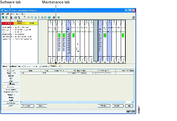
When you upgrade CTC software, the TCC2/TCC2P cards store the new CTC version as the protect CTC version. When you activate the new CTC software, the TCC2/TCC2P cards store the older CTC version as the protect CTC version, and the newer CTC release becomes the working version. You can view the software versions that are installed on an ONS 15454 by selecting the Maintenance > Software tabs in node view (single-shelf mode) or multishelf view (multishelf mode) ( Figure 12-1).
Figure 12-1 CTC Software Versions, Node View (Single-Shelf Mode)
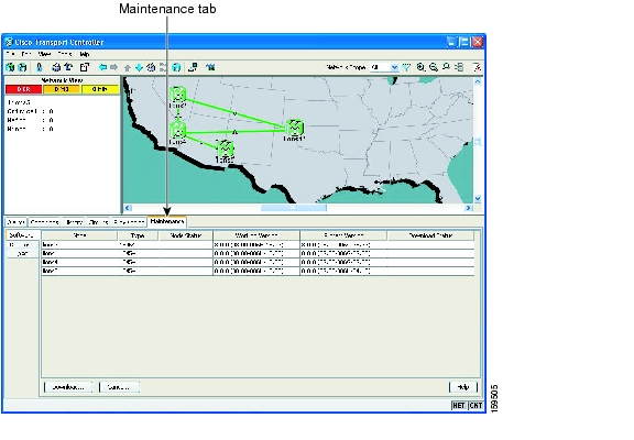
Select the Maintenance > Software tabs in network view to display the software versions installed on all the network nodes ( Figure 12-2).
Figure 12-2 CTC Software Versions, Network View
12.1.2 CTC Software Installed on the PC or UNIX Workstation
CTC software is downloaded from the TCC2/TCC2P cards and installed on your computer automatically after you connect to the ONS 15454 with a new software release for the first time. Downloading the CTC software files automatically ensures that your computer is running the same CTC software version as the TCC2/TCC2P cards you are accessing. The CTC files are stored in the temporary directory designated by your computer operating system. You can use the Delete CTC Cache button to remove files stored in the temporary directory. If the files are deleted, they download the next time you connect to an ONS 15454. Downloading the Java archive (JAR) files for CTC takes several minutes depending on the bandwidth of the connection between your workstation and the ONS 15454. For example, JAR files downloaded from a modem or a data communications channel (DCC) network link require more time than JAR files downloaded over a LAN connection.
During network topology discovery, CTC polls each node in the network to determine which one contains the most recent version of the CTC software. If CTC discovers a node in the network that has a more recent version of the CTC software than the version you are currently running, CTC generates a message stating that a later version of the CTC has been found in the network and offers to install the CTC software upgrade. After the node view appears, you can upgrade CTC by using the Tools > Update CTC menu option. If you have network discovery disabled, CTC will not seek more recent versions of the software. Unreachable nodes are not included in the upgrade discovery.
Note
12.2 CTC Installation Overview
To connect to an ONS 15454 using CTC, you enter the ONS 15454 IP address in the URL field of Netscape Navigator or Microsoft Internet Explorer. After connecting to an ONS 15454, the following occurs automatically:
1.
2.
3.
4.
Each ONS 15454 can handle up to five concurrent CTC sessions. CTC performance can vary, depending upon the volume of activity in each session, network bandwidth, and TCC2/TCC2P card load.
Note
12.3 PC and UNIX Workstation Requirements
To use CTC for the ONS 15454, your computer must have a web browser with the correct Java Runtime Environment (JRE) installed. The correct JRE for each CTC software release is included on the Cisco ONS 15454 software CD. If you are running multiple CTC software releases on a network, the JRE installed on the computer must be compatible with the different software releases.
When you change the JRE version on the JRE tab, you must exit and restart CTC for the new JRE version to take effect. Table 12-1 shows JRE compatibility with ONS 15454 software releases.
Table 12-1 JRE Compatibility
ONS 15454 Release 4.5
No
Yes
No
No
ONS 15454 Release 4.6
No
Yes
Yes
No
ONS 15454 Release 4.7
No
No
Yes
No
ONS 15454 Release 5.0
No
No
Yes
No
ONS 15454 Release 6.0
No
No
Yes
No
ONS 15454 Release 7.0
No
No
Yes
Yes 1
ONS 15454 Release 7.2
No
No
Yes
Yes 1
ONS 15454 Release 8.0
No
No
No
Yes
1 JRE 1.4.2 is the preferred version which is included in the software CD
Table 12-2 lists the requirements for PCs and UNIX workstations. In addition to the JRE, the Java plug-in is also included on the ONS 15454 software CD.
12.4 ONS 15454 Connections
You can connect to the ONS 15454 in multiple ways. You can connect your PC directly to the ONS 15454 (local craft connection) using the RJ-45 port on the TCC2/TCC2P card or, for the ANSI shelf, using the LAN pins on the backplane (the ETSI shelf provides a LAN connection via the RJ-45 jack on the MIC-T/C/P Front Mount Electrical Connection [FMEC]). Alternatively, you can connect your PC to a hub or switch that is connected to the ONS 15454, connect to the ONS 15454 through a LAN or modem, or establish TL1 connections from a PC or TL1 terminal. Table 12-3 lists the ONS 15454 connection methods and requirements.
12.5 CTC Window
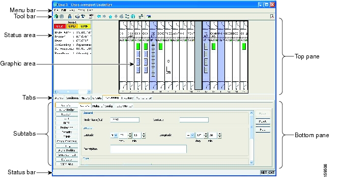
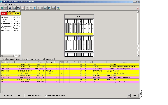
When you log into a single-shelf ONS 15454, the CTC window appears in node view ( Figure 12-3). When you log into a multishelf ONS 15454, meaning that two or more ONS 15454 shelves are configured to operate as one node, the multishelf view ( Figure 12-4) appears in the CTC window. The window includes a menu bar, a toolbar, and a top and bottom pane. The top pane provides status information about the selected objects and a graphic of the current view. The bottom pane provides tabs and subtabs to view ONS 15454 information and perform ONS 15454 provisioning and maintenance tasks. From the CTC window, you can display the other ONS 15454 views. In single-shelf mode, these are the network, node, and card views. In multishelf mode, these are the network, multishelf, shelf, and card views.
Figure 12-3 Node View (Default Login View for Single-Shelf Mode)
Figure 12-4 Multishelf View (Default Login View for Multishelf Mode)
12.5.1 Node View (Multishelf Mode), Node View (Single-Shelf Mode), and Shelf View (Multishelf Mode)
Node view, shown in Figure 12-3, is the first view that appears after you log into a single-shelf ONS 15454. Multishelf view, shown in Figure 12-4, is the first view that appears after you log into a multishelf ONS 15454. The login node is the first node shown, and it is the "home view" for the session. Multishelf view and node view allow you to manage one ONS 15454 node. The status area shows the node name; IP address; session boot date and time; number of Critical (CR), Major (MJ), and Minor (MN) alarms; name and security level of the current logged-in user; software version; and network element default setup.
In a multishelf mode, up to eight shelves operate as a single node. When you open a shelf from multishelf view, shelf view appears, which looks similar to node view but does not contain the tabs and subtabs that are used for node-level operations.
12.5.1.1 CTC Card Colors
The graphic area of the CTC window depicts the ONS 15454 shelf assembly. The colors of the cards in the graphic reflect the real-time status of the physical card and slot ( Table 12-4).
On the ONS 15454 ETSI, the colors of the FMEC cards reflect the real-time status of the physical FMEC cards. Table 12-5 lists the FMEC card colors. The FMEC ports shown in CTC do not change color.
Note
The wording on a card in node view (single-shelf mode) or shelf view (multishelf mode) shows the status of a card (Active, Standby, Loading, or Not Provisioned). Table 12-6 lists the card statuses.
Port color in card view, node view (single-shelf mode), and shelf view (multishelf mode) indicates the port service state. Table 12-7 lists the port colors and their service states. For more information about port service states, see "Administrative and Service States."
Table 12-7 Node View (Single-Shelf Mode) or Shelf View (Multishelf Mode) Card Port Colors and Service States
Cyan (blue)
Out-of-Service and Management, Loopback (OOS-MA,LPBK) (ANSI)
Locked-enabled,loopback (ETSI)
Port is in a loopback state. On the card in node or shelf view, a line between ports indicates that the port is in terminal or facility loopback (see Figure 12-5 and Figure 12-6). Traffic is carried and alarm reporting is suppressed. Raised fault conditions, whether or not their alarms are reported, can be retrieved on the CTC Conditions tab or by using the TL1 RTRV-COND command.
Cyan (blue)
Out-of-Service and Management, Maintenance (OOS-MA,MT) (ANSI)
Locked-enabled,maintenance (ETSI)
Port is out-of-service for maintenance. Traffic is carried and loopbacks are allowed. Alarm reporting is suppressed. Raised fault conditions, whether or not their alarms are reported, can be retrieved on the CTC Conditions tab or by using the TL1 RTRV-COND command. Use this service state for testing or to suppress alarms temporarily. Change the state to IS-NR/Unlocked-enabled; OOS-MA,DSBLD/Locked-enabled,disabled; or OOS-AU,AINS/Unlocked-disabled,automaticInService when testing is complete.
Gray
Out-of-Service and Management, Disabled (OOS-MA,DSBLD) (ANSI)
Locked-enabled,disabled (ETSI)
The port is out-of-service and unable to carry traffic. Loopbacks are not allowed in this service state.
Green
In-Service and Normal (IS-NR) (ANSI)
Unlocked-enabled (ETSI)
The port is fully operational and performing as provisioned. The port transmits a signal and displays alarms; loopbacks are not allowed.
Violet
Out-of-Service and Autonomous, Automatic In-Service (OOS-AU,AINS) (ANSI)
Unlocked-disabled,automaticInService (ETSI)
The port is out-of-service, but traffic is carried. Alarm reporting is suppressed. The node monitors the ports for an error-free signal. After an error-free signal is detected, the port stays in this service state for the duration of the soak period. After the soak period ends, the port service state changes to IS-NR/Unlocked-enabled.
Raised fault conditions, whether or not their alarms are reported, can be retrieved on the CTC Conditions tab or by using the TL1 RTRV-COND command. The AINS port will automatically transition to IS-NR/Unlocked-enabled when a signal is received for the length of time provisioned in the soak field.
Figure 12-5 Terminal Loopback Indicator
Figure 12-6 Facility Loopback Indicator
12.5.1.2 Multishelf View Card Shortcuts
If you move your mouse over cards in the multishelf view graphic, popups display additional information about the card including the card type; the card status (active or standby); the type of alarm, such as Critical, Major, or Minor (if any); the alarm profile used by the card; and for transponder (TXP) or muxponder (MXP) cards, the wavelength of the dense wavelength division multiplexing (DWDM) port.
12.5.1.3 Node View (Single-Shelf Mode) or Shelf View (Multishelf Mode) Card Shortcuts
If you move your mouse over cards in the node view (single-shelf mode) or shelf view (multishelf mode) graphic, popups display additional information about the card including the card type; the card status (active or standby); the type of alarm, such as Critical, Major, or Minor (if any); the alarm profile used by the card; and for TXP or MXP cards, the wavelength of the DWDM port. Right-click a card to reveal a shortcut menu, which you can use to open, reset, delete, or change a card. Right-click a slot to preprovision a card (that is, provision a slot before installing the card).
12.5.1.4 Multishelf View Tabs
Table 12-8 lists the tabs and subtabs available in the multishelf view. The actions on these tabs apply to the multishelf node and its subtending shelves.
12.5.1.5 Node View (Single-Shelf Mode) or Shelf View (Multishelf Mode) Tabs
Table 12-9 lists the tabs and subtabs available in node view (single-shelf mode) or shelf view (multishelf mode).
12.5.2 Network View
Network view allows you to view and manage ONS 15454s that have DCC connections to the node that you logged into and any login node groups you have selected ( Figure 12-7).
Figure 12-7 Network in CTC Network View
Note
The graphic area displays a background image with colored ONS 15454 icons. A Superuser can set up the logical network view feature, which enables each user to see the same network view.
12.5.2.1 Network View Tabs
Table 12-10 lists the tabs and subtabs available in network view.
12.5.2.2 CTC Node Colors
The color of a node in network view, shown in Table 12-11, indicates the node alarm status.
12.5.2.3 DCC Links
The lines show DCC connections between the nodes ( Table 12-12). DCC connections can be green (active) or gray (fail). The lines can also be solid (circuits can be routed through this link) or dashed (circuits cannot be routed through this link). Circuit provisioning uses active/routable links. Selecting a node or span in the graphic area displays information about the node and span in the status area.
12.5.2.4 Link Consolidation
CTC provides the ability to consolidate the DCC, generic communications channel (GCC), optical transmission section (OTS), and PPC links shown in the network view into a more streamlined view. Link consolidation allows you to condense multiple inter-nodal links into a single link. The link consolidation sorts links by class, meaning that all DCC links are consolidated together, for example.You can access individual links within consolidated links using the right-click shortcut menu.Each link has an associated icon ( Table 12-13).
Note
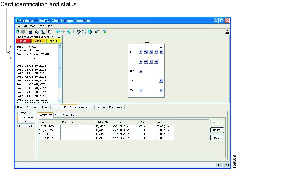
12.5.3 Card View
The card view provides information about individual ONS 15454 cards. Use this window to perform card-specific maintenance and provisioning ( Figure 12-8). A graphic showing the ports on the card is shown in the graphic area. The status area displays the node name, slot, number of alarms, card type, equipment type, card status (active or standby), card service state if the card is present, and port service state (described in Table 12-7). The information that appears and the actions that you can perform depend on the card. For more information about card service states, refer to "Administrative and Service States."
Figure 12-8 CTC Card View Showing a 40-WXC-C Card
Note
Use the card view tabs and subtabs shown in Table 12-14 to provision and manage the ONS 15454. The subtabs, fields, and information shown under each tab depend on the card type selected.
12.6 Using the CTC Launcher Application to Manage Multiple ONS Nodes
The CTC Launcher application is an executable file, StartCTC.exe, that is provided on Software Release 8.0 CDs for Cisco ONS products. You can use CTC Launcher to log into multiple ONS nodes that are running CTC Software Release 3.3 or higher, without using a web browser. The CTC launcher application provides an advantage particularly when you have more than one NE version on the network, because it allows you to pick from all available CTC software versions. It also starts more quickly than the browser version of CTC and has a dedicated node history list.
CTC Launcher provides two connection options. The first option is used to connect to ONS NEs that have an IP connection to the CTC computer. The second option is used to connect to ONS NEs that reside behind third party, OSI-based GNEs. For this option, CTC Launcher creates a TL1 tunnel to transport the TCP traffic through the OSI-based GNE.
The TL1 tunnel transports the TCP traffic to and from ONS ENEs through the OSI-based GNE. TL1 tunnels are similar to the existing static IP-over-CLNS tunnels, GRE, and Cisco IP, that can be created at ONS NEs using CTC. (Refer to the Cisco ONS product documentation for information about static IP-over-CLNS tunnels.) However, unlike the static IP-over-CLNS tunnels, TL1 tunnels require no provisioning at the ONS ENE, the third-party GNE, or DCN routers. All provisioning occurs at the CTC computer when the CTC Launcher is started.
Figure 12-9 shows examples of two static IP-over-CLNS tunnels. A static Cisco IP tunnel is created from ENE 1 through other vendor GNE 1 to a DCN router, and a static GRE tunnel is created from ONS ENE 2 to the other vender, GNE 2. For both static tunnels, provisioning is required on the ONS ENEs. In addition, a Cisco IP tunnel must be provisioned on the DCN router and a GRE tunnel provisioned on GNE 2.
Figure 12-9 Static IP-Over-CLNS Tunnels
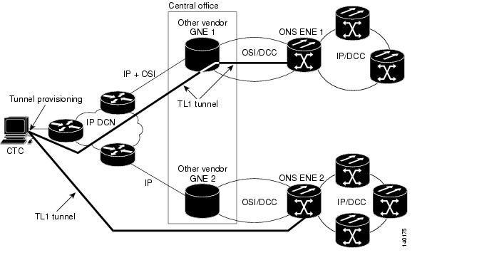
Figure 12-10 shows the same network using TL1 tunnels. Tunnel provisioning occurs at the CTC computer when the tunnel is created with the CTC Launcher. No provisioning is needed at ONS NEs, GNEs, or routers.
Figure 12-10 TL1 Tunnels
TL1 tunnels provide several advantages over static IP-over-CLNS tunnels. Because tunnel provisioning is needed only at the CTC computer, they are faster to set up. Because they use TL1 for TCP transport, they are more secure. TL1 tunnels also provide better flow control. On the other hand, IP over CLNS tunnels require less overhead and usually provide a slight performance edge over TL1 Tunnels (depending on network conditions). TL1 tunnels do not support all IP applications such as SNMP and RADIUS Authentication. Table 12-15 shows a comparison between the two types of tunnels.
TL1 tunnel specifications and general capabilities include:
•
•
•
•
•
12.7 TCC2/TCC2P Card Reset
You can reset the ONS 15454 TCC2/TCC2P card by using CTC (a soft reset) or by physically reseating the card (a hard reset). A soft reset reboots the TCC2/TCC2P card and reloads the operating system and the application software. Additionally, a hard reset temporarily removes power from the TCC2/TCC2P card and clears all buffer memory.
You can apply a soft reset from CTC to either an active or standby TCC2/TCC2P card without affecting traffic. If you need to perform a hard reset on an active TCC2/TCC2P card, put the TCC2/TCC2P card into standby mode first by performing a soft reset.
Note
12.8 TCC2/TCC2P Card Database
When dual TCC2/TCC2P cards are installed in the ONS 15454, each TCC2/TCC2P card hosts a separate database; therefore, the protect card database is available if the database on the working TCC2/TCC2P fails. You can also store a backup version of the database on the workstation running CTC. This operation should be part of a regular ONS 15454 maintenance program at approximately weekly intervals, and should also be completed when preparing an ONS 15454 for a pending natural disaster, such as a flood or fire.
Note
12.9 Software Revert
When you click the Activate button after a software upgrade, the TCC2/TCC2P card copies the current working database and saves it in a reserved location in the TCC2/TCC2P card flash memory. If later during the upgrade you need to revert to the original working software load from the protect software load, the saved database installs automatically. You do not need to restore the database manually or recreate circuits.
The revert feature is useful if the maintenance window in which you were performing an upgrade closes while you are still upgrading CTC software. You can revert to the protect software load without losing traffic. During the next maintenance window, you can complete the upgrade and activate the new software load.
Circuits created or provisioning done after you activate a new software load (upgrade to a higher release) will be lost with a revert. The database configuration at the time of activation is reinstated after a revert. (This does not apply to maintenance reverts, such as Software R5.0.1 to Software R5.0.2, because maintenance releases retain the database during activation.)
Caution
To perform a supported (non-service-affecting) revert from a software release that you have just activated, the release you revert to must have been working at the time you first activated the new software on that node. Because a supported revert automatically restores the node configuration at the time of the previous activation, any configuration changes made after activation will be lost when you revert the software. Downloading the software release that you are upgrading to a second time after you have activated the new load ensures that no actual revert to a previous load can take place (the TCC2/TCC2P will reset, but will not be traffic affecting and will not change your database).
Note
![]()
![]()
![]()
![]()
![]()
![]()
![]()
![]()
Posted: Mon Oct 22 05:37:13 PDT 2007
All contents are Copyright © 1992--2007 Cisco Systems, Inc. All rights reserved.
Important Notices and Privacy Statement.