|
|

Table Of Contents
Optical Channel Circuits and Virtual Patchcords Reference
11.1.1 Administrative and Service States
11.1.2 Creating and Deleting OCHCCs
11.1.3 OCHCCs and Service and Communications Channels
Optical Channel Circuits and Virtual Patchcords Reference
This chapter explains the Cisco ONS 15454 dense wavelength division multiplexing (DWDM) optical channel (OCH) circuit types and virtual patchcords that can be provisioned on the ONS 15454. Circuit types include the OCH client connection (OCHCC), the OCH trail, and the OCH network connection (OCHNC). Virtual patchcords include internal patchcords and provisionable (external) patchcords (PPCs).
Note
Unless otherwise specified, "ONS 15454" refers to both ANSI and ETSI shelf assemblies.
11.1 Optical Channel Circuits
The ONS 15454 DWDM optical circuits provide end-to-end connectivity through three OCH circuit types: OCHNCs, OCHCCs, and OCH trails.
OCHNCs establish connectivity between two optical nodes upon a specified C-band or L-band wavelength through the ports residing on wavelength selective switches, multiplexers, demultiplexer, and add/drop cards, as shown in Table 11-1.
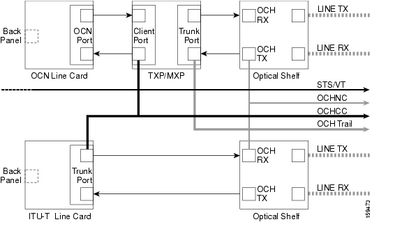
OCHCC circuits extend the OCHNC to create an end-to-end optical connection from client card to client card. OCHCCs are transported by OCH trails. OCH trail circuits create an optical connection from the source client card trunk port to the destination client card trunk port. Each OCH trail is associated to one or more OCHNCs. Figure 11-1 shows the relationships and optical flow between the OCHCC, the OCH trail, and the OCHNC.
Figure 11-1 Optical Channel Management
Each OCHCC circuit is associated to a pair of client or trunk ports on the transponder (TXP), muxponder (MXP), GE_XP, 10GE_XP, or ITU-T line card. Each OCH trail is associated to a pair of trunk ports on the TXP, MXP, GE_XP, 10GE_XP, or ITU-T line card. The OCH trail ports are automatically associated to the OCHCC. If the OCHCC is created between two TXP, MXP, GE_XP, or 10GE_XP cards, two ports belong to the OCHCC at each circuit end:
•
•
If the OCHCC is created between two TXPP or two MXPP cards, three ports belong to the OCHCC at each end:
•
•
If the OCHCC is created between two ITU-T line cards, only one trunk port belongs to the OCHCC at each end. Table 11-2 lists the ports that can be OCHCC and OCH trail endpoints.
11.1.1 Administrative and Service States
OCHCCs, OCH trails, and OCHNCs occupy three different optical layers. Each OCH circuit has its own administrative and service states. The OCHCCs impose additional restrictions on changes that can be made to client card port administrative state.
The OCHCC service state is the sum of the OCHCC service state and the OCH trail service state. When creating an OCHCC circuit, you can specify an initial state for both the OCHCC and the OCH trail layers, including the source and destination port states. The ANSI/ETSI administrative states for the OCHCC circuits and connections are:
•
•
•
OCHCC service states and source and destination port states can be changed independently. You can manually modify client card port states in all traffic conditions. Setting an OCHCC circuit to OOS,DSBLD/Locked,disabled state has no effect on OCHCC client card ports.
An OCH trail is created automatically when you create an OCHCC. OCH trails can be created independently between OCH-10G cards and GE_XP and 10GE_XP when they are provisioned in Layer 2 Over DWDM mode. The OCH trail ANSI/ETSI administrative states include:
•
•
•
You can modify OCH trail circuit states from the Edit Circuit window. Placing an OCH trail OOS,DSBLD/Locked,disabled causes the following state changes:
•
•
Changing the OCH trail state to IS,AINS/Unlocked,automaticInService causes the following state changes:
•
•
The OCH trail service state is the sum of the OCHCC trunk port state and the OCHNC (if applicable) state. Changing the client card trunk ports to OOS,DSBLD/Locked,disabled when the OCH trail state IS/Unlocked will cause the OCH trail state to change to OOS,DSBLD/Locked,disabled and its status to change to Partial.
The OCHNC circuit states are not linked to the OCHCC circuit states. The administrative states for the OCHNC circuit layer are:
•
•
When you create an OCHNC, you can set the target OCHNC circuit state to IS/Unlocked or OOS,DSBLD/Locked,disabled. You can create an OCHNC even if OCHNC source and destination ports are OOS,MT/Locked,maintenance. The OCHNC circuit state will remain OOS-AU,AINS/Unlocked-disabled,automaticInService until the port maintenance state is removed. During maintenance or laser shutdown, the following behavior occurs:
•
•
OCHCCs are associated with the client card end ports. Therefore, the following port parameters cannot be changed when they carry an OCHCC:
•
•
•
•
•
•
Certain OCHCC parameters, such as service type, service size, and OCHNC wavelength can only be modified by deleting and recreating the OCHCC. If the OCHCC has MXP end ports, you can modify services and parameters on client ports that are not allocated to the OCHCC. Some client port parameters, such as Ethernet frame size and distance extension, are not part of an OCHCC so they can be modified if not restricted by the port state. For addition information about administrative and service states, see "Administrative and Service States."
11.1.2 Creating and Deleting OCHCCs
To create an OCHCC, you must know the client port states and their parameters. If the client port state is IS/Unlocked, OCHCC creation will fail if the OTN line parameters (ITU-T G.709, FEC, signal fail bit error rate (SF BER), and signal degrade bit error rate (SD BER) on the OCHCC differ from what is provisioned on the trunk port. The port state must be changed to OOS-DSLB/Locked,disabled in order to complete the OCHCC.
If you delete an OCHCC, you can specify the administrative state to apply to the client card ports. For example, you can have the ports placed in OOS,DSBLD/Locked,disabled state after an OCHCC is deleted. If you delete an OCHCC that originates and terminates on MXP cards, the MXP trunk port states can only be changed if the trunk ports do not carry other OCHCCs.
11.1.3 OCHCCs and Service and Communications Channels
Although optical service channels (OSCs), generic communications channels (GCCs), and data communications channels (DCCs) are not managed by OCHCCs, the following restrictions must be considered when creating or deleting OCHCCs on ports with service or communication channels:
•
•
•
11.2 Virtual Patchcords
TXP, MXP, TXPP, MXPP, GE_XP, 10GE_XP, and ADM-10G client ports and DWDM filter ports can be located in different nodes or in the same single-shelf or multishelf node. ITU-T line card trunk ports and the corresponding DWDM filter ports are usually located in different nodes.
OCHCC provisioning requires a virtual patchcord between the client card trunk ports and the DWDM filter ports. Depending on the physical layout, this can be an internal patchcord or a provisionable (external) patchcord (PPC). Both patchcord types are bidirectional. However, each direction is managed as a separate patchcord.
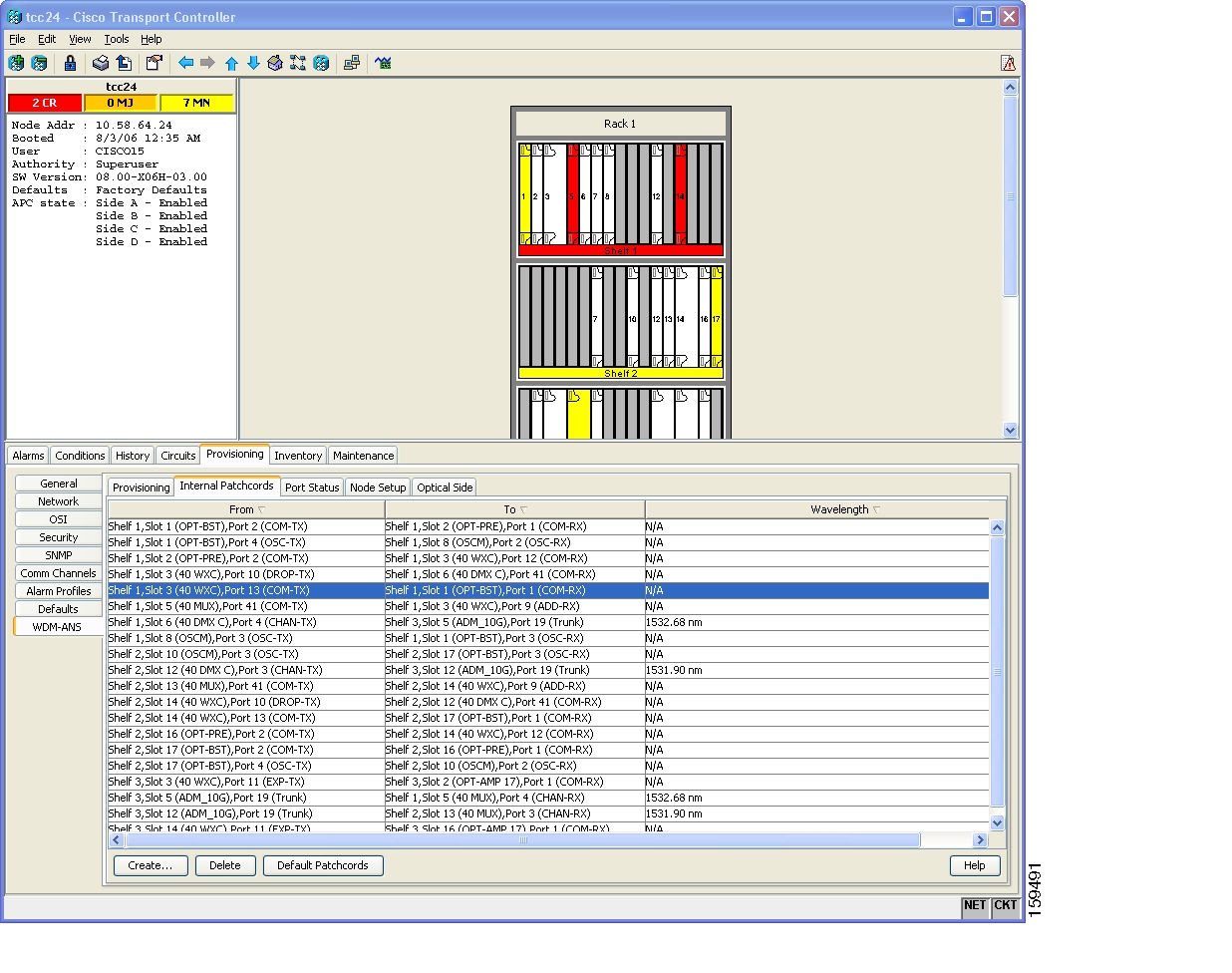
Internal patchcords provide virtual links between the two sides of a DWDM shelf, either in single-shelf or multishelf mode. They are viewed and managed on the Provisioning > WDM-ANS > Internal Patchcords tab ( Figure 11-2).
Figure 11-2 Internal Patchcords Tab
CTC calculates internal patchcords automatically after you click the Default Patchcords button on the Internal Patchcords tab. However, some internal patchcords cannot be calculated because of the card types that are installed and/or the card positions within a shelf. These internal patchcords must be created manually. For example, internal patchcords related to optical bypass circuits must be manually provisioned. When you create an internal patchcord manually, the Internal Patchcord Creation wizard asks you to choose one of the following internal patchcord types:
•
•
Note
•
Table 11-3 shows the internal patchcord OCH trunk, OCH filter, and OTS/OCH ports.
Table 11-3 Internal Patchcord Ports
TXPs
MXPs
GE_XP
10GE_XP
ADM-10G
ITU-T line cards
Any trunk port
—
—
OPT-BST
OPT-BST-E
OPT-BST-L
—
—
COM-TX
COM-RX
OSC-TX
OSC-RX
OPT-AMP-17-C
OPT-AMP-L
—
—
COM-TX
COM-RX
OSC-TX1
OSC-RX1
DC-TX1
DC-RX1
OPT-PRE
—
—
COM-TX
COM-RX
DC-TX
DC-RX
OSCM
OSC-CSM
—
—
COM-TX
COM-RX
OSC-TX
OSC-RX
32MUX
32MUX-O
40-MUX-C
—
Any CHAN RX port
COM-TX
32DMX
32DMX-L
32DMX-O
40-DMX-C
—
Any CHAN TX port
COM-RX
32WSS
32WSS-L
40-WSS-C
—
Any ADD port
COM-TX
COM-RX
EXP-TX
EXP-RX
DROP-TX
40-WXC-C
—
—
ADD-RX
DROP-TX
COM TX
COM RX
MMU
—
—
EXP A TX
EXP A RX
1 When provisioned in OPT-PRE mode.
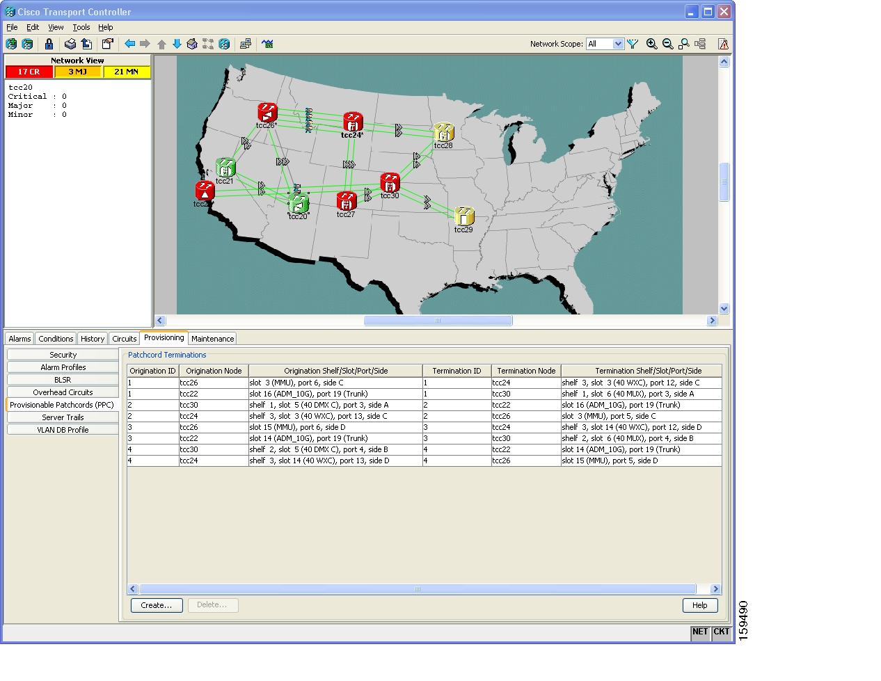
PPCs are created and managed from the network view Provisioning > Provisionable Patchcord (PPC) tab ( Figure 11-3), or from the node view (single-shelf mode) or multiself view (multishelf mode) Provisioning > Comm Channel > PPC tab.
Figure 11-3 Network View Provisionable Patchcords Tab
PPCs are required when the TXP, MXP, GE_XP, 10GE_XP, ADM-10G, or ITU-T line card is installed in a different node than the OCH filter ports. They can also be used to create OTS-to-OTS links between shelves that do not have OSC connectivity. PPCs are routable and can be used for network topology discovery by Open Shortest Path First (OSPF). GCCs and DCCs are not required for PPC creation. When you create a PPC, the PPC Creation wizard asks you to choose one of the following PPC types:
•
•
•
Table 11-4 shows the PPC OCH trunk, OCH filter, and OTS ports.
Table 11-4 Provisionable Patchcord Ports
TXPs
MXPs
GE_XP
10GE_XP
ADM-10G
ITU-T line cards
Any trunk port
—
—
OPT-BST
OPT-BST-E
OPT-BST-L
—
COM RX1
LINE RX
LINE TX
—
OPT-AMP-17-C
OPT-AMP-L
—
COM RX2
COM TX3
LINE RX3
LINE TX3
—
OPT-PRE
—
COM RX4
COM TX4
—
OSC-CSM
—
COM RX1
LINE RX
LINE TX
—
32MUX
32MUX-O
40-MUX-C
—
—
Any CHAN RX port
32DMX
32DMX-L
32DMX-O
40-DMX-C
—
—
Any CHAN TX port
32WSS
32WSS-L
40-WSS-C
—
—
Any ADD port
40-WXC-C
—
COM RX
COM TX
—
MMU
—
EXP A RX
EXP A TX
—
1 Line nodes only.
2 When Card Mode is OPT-PRE.
3 When Card Mode is OPT-LINE.
4 Line nodes with two OPT-PRE cards and no BST cards installed.
For OCH trunk to OCH filter PPCs, the following rules and conditions apply:
•
•
•
•
•
For OCH-trunk to OCH-trunk PPCs, the following rules and conditions apply:
•
•
•
![]()
![]()
![]()
![]()
![]()
![]()
![]()
![]()
Posted: Mon Oct 22 05:35:36 PDT 2007
All contents are Copyright © 1992--2007 Cisco Systems, Inc. All rights reserved.
Important Notices and Privacy Statement.