|
|

Table Of Contents
DLP-A412 Install the DCU Shelf Assembly
DLP-A416 View Circuit Information
DLP-A418 Install Public-Key Security Certificate
DLP-A421 Provision G-Series and CE-1000-4 Flow Control Watermarks
DLP-A422 Verify BLSR Extension Byte Mapping
DLP-A428 Install Fiber-Optic Cables in a 1+1 Configuration
DLP-A430 View Spanning Tree Information
DLP-A431 Change the JRE Version
DLP-A433 Enable Node Secure Mode
DLP-A435 Modify Backplane Port IP Settings in Secure Mode
DLP-A436 Disable Node Security Mode
DLP-A437 Change a VCAT Member Service State
DLP-A438 Change General Port Settings for the FC_MR-4 Card
DLP-A439 Change Distance Extension Port Settings for the FC_MR-4 Card
DLP-A440 Change Enhanced FC/FICON Port Settings for the FC_MR-4 Card
DLP-A441 Install Electrical Cables on the UBIC-H EIAs
DLP-A442 Verify Pass-Through Circuits
DLP-A443 Install the Fiber Clip on 15454_MRC-12 Cards
DLP-A444 Provision a PPM on the MRC-12 Card
DLP-A445 Provision the Optical Line Rate on the MRC-12 Card
DLP-A446 Change the Optical Line Rate on the MRC-12 Card
DLP-A447 Delete a PPM from the MRC-12 or OC192-XFP Card
DLP-A448 Convert DS3XM-6 or DS3XM-12 Cards From 1:1 to 1:N Protection
DLP-A449 Set Up SNMP for a GNE
DLP-A450 Set Up SNMP for an ENE
DLP-A451 Format and Enter NMS Community String for SNMP Command or Operation
DLP-A453 Delete a Server Trail
DLP-A454 View the BLSR STS Squelch Table
DLP-A455 View the BLSR VT Squelch Table
DLP-A456 Configure the Node for RADIUS Authentication
DLP-A457 Grant Superuser Privileges to a Provisioning User
DLP-A459 Change Optics Thresholds Settings for OC-192 and MRC-12 Cards
DLP-A460 Reset a Traffic Card Using CTC
DLP-A461 Preprovision an SFP or XFP Device
DLP-A462 View and Terminate Active Logins
DLP-A463 Roll the Source or Destination of One Optical Circuit
DLP-A464 Roll One Cross-Connect from an Optical Circuit to a Second Optical Circuit
DLP-A465 Roll Two Cross-Connects on One Optical Circuit Using Automatic Routing
DLP-A466 Roll Two Cross-Connects on One Optical Circuit Using Manual Routing
DLP-A467 Roll Two Cross-Connects from One Optical Circuit to a Second Optical Circuit
DLP-A469 Install a GBIC or SFP/XFP Device
DLP-A470 Remove GBIC or SFP/XFP Devices
DLP-A495 Consolidate Links in Network View
DLP-A498 Switch Between TDM and DWDM Network Views
DLPs A400 to A499
Note
The terms "Unidirectional Path Switched Ring" and "UPSR" may appear in Cisco literature. These terms do not refer to using Cisco ONS 15xxx products in a unidirectional path switched ring configuration. Rather, these terms, as well as "Path Protected Mesh Network" and "PPMN," refer generally to Cisco's path protection feature, which may be used in any topological network configuration. Cisco does not recommend using its path protection feature in any particular topological network configuration.
DLP-A412 Install the DCU Shelf Assembly
Warning
Step 1
Step 2
Step 3
Step 4
Step 5
DLP-A416 View Circuit Information
Step 1
•
•
•
Note
Step 2
•
•
•
•
•
•
•
•
•
•
•
•
•
–
–
–
Step 3
DLP-A418 Install Public-Key Security Certificate
Purpose
This task installs the ITU Recommendation X.509 public-key security certificate. The public-key certificate is required to run Software Release 4.1 or later.
Tools/Equipment
None
Prerequisite Procedures
This task is performed during the "DLP-A60 Log into CTC" task on page 17-68. You cannot perform it outside of this task.
Required/As Needed
Required
Onsite/Remote
Onsite or remote
Security Level
Provisioning or higher
Step 1
•
•
•
•
Step 2
•
•
Caution
Step 3
DLP-A421 Provision G-Series and CE-1000-4 Flow Control Watermarks
Step 1
Step 2
Step 3
Step 4
a.
The Flow Ctrl Lo and Flow Ctrl Hi values change.
b.
Step 5
a.
b.
c.
This value sets the flow control threshold for sending the signal to the attached Ethernet device to resume transmission.
d.
e.
This value sets the flow control threshold for sending the signal to the attached Ethernet device to pause transmission.
f.
Note
Step 6
DLP-A422 Verify BLSR Extension Byte Mapping
Step 1
Step 2
Step 3
Step 4
Step 5
Step 6
Step 7
Step 8
DLP-A428 Install Fiber-Optic Cables in a 1+1 Configuration
Note
Note
Note
Step 1
Step 2
Step 3
Step 4
DLP-A430 View Spanning Tree Information
Step 1
Step 2
•
•
•
•
Step 3
DLP-A431 Change the JRE Version
Step 1
Step 2
Step 3
Step 4
Step 5
Step 6
Step 7
Step 8
Step 9
DLP-A433 Enable Node Secure Mode
Purpose
This task enables secure mode on the ONS 15454. When secure mode is enabled, two IP addresses are assigned to the node: one address is assigned to the backplane LAN port and the other is assigned to the TCC2P RJ-45 TCP/IP (LAN) port.
Tools/Equipment
TCC2P cards must be installed.
Prerequisite Procedures
NTP-A108 Back Up the Database, page 15-5
Required/As Needed
As needed
Onsite/Remote
Onsite or remote
Security Level
Superuser
Caution
Note
Step 1
Step 2
Step 3
Step 4
Step 5
Step 6
Step 7
Step 8
•
•
Step 9
Within the next 30 to 40 seconds, the TCC2P cards reboot. CTC switches to network view, and the CTC Alerts dialog box appears. In network view, the node changes to gray and a DISCONNECTED condition appears.
Step 10
Step 11
a.
b.
c.
d.
e.
Note
Step 12
DLP-A434 Lock Node Security
Purpose
This task locks the secure mode configuration on an ONS 15454. When secure mode is locked, two IP addresses must always be provisioned on the ONS 15454: one for the TCC2P TCP/IP (LAN) port and one for the backplane LAN port.
Tools/Equipment
TCC2P cards must be installed.
Prerequisite Procedures
DLP-A60 Log into CTC, page 17-68
Required/As Needed
As needed
Onsite/Remote
Onsite or remote
Security Level
Superuser
Caution
Note
Step 1
Step 2
Step 3
Step 4
DLP-A435 Modify Backplane Port IP Settings in Secure Mode
Purpose
This task modifies the ONS 15454 backplane IP address, subnet mask, and default router. It also modifies settings that control backplane IP address visibility in CTC and the ONS 15454 LCD. To perform this task, secure mode must be enabled.
Tools/Equipment
TCC2P cards must be installed.
Prerequisite Procedures
NTP-A108 Back Up the Database, page 15-5
DLP-A60 Log into CTC, page 17-68
Required/As Needed
As needed
Onsite/Remote
Onsite or remote
Security Level
Superuser
Caution
Caution
Step 1
Step 2
•
•
•
•
–
–
–
•
Step 3
If you changed the IP address, subnet mask, or default router, the node will reboot. This will take 5 to 10 minutes.
Step 4
DLP-A436 Disable Node Security Mode
Purpose
This task disables the ONS 15454 secure mode, meaning dual-IP addresses are no longer supported.With secure mode disabled, only one IP address can be provisioned for both the backplane LAN port and the TCC2P TCP/IP (LAN) port. If secure mode is disabled for a node, that node cannot identify other network nodes that are in secure mode.
Tools/Equipment
TCC2P cards must be installed.
Prerequisite Procedures
NTP-A108 Back Up the Database, page 15-5
Required/As Needed
As needed
Onsite/Remote
Onsite or remote
Security Level
Superuser
Note
Note
Note
Step 1
Step 2
Step 3
Step 4
•
•
•
Step 5
Step 6
•
•
•
Step 7
Within the next 30 to 40 seconds, the TCC2P cards reboot. CTC switches to network view, and the CTC Alerts dialog box appears. In network view, the node changes to gray and a DISCONNECTED condition appears.
Step 8
Step 9
DLP-A437 Change a VCAT Member Service State
Purpose
This task displays the Edit Circuit window for VCAT members, where you can change the service state.
Tools/Equipment
None
Prerequisite Procedures
DLP-A60 Log into CTC, page 17-68
VCAT circuits must exist on the network. See the "NTP-A264 Create an Automatically Routed VCAT Circuit" procedure on page 6-82 or the "NTP-A265 Create a Manually Routed VCAT Circuit" procedure on page 6-87.
Required/As Needed
As needed
Onsite/Remote
Onsite or remote
Security Level
Provisioning or higher
Note
Step 1
Step 2
Step 3
Step 4
Step 5
Note
Step 6
•
•
•
•
•
Note the following behavior of the two VCAT members on ML-Series cards (both SW-LCAS and non-LCAS members):
•
•
Step 7
Step 8
Step 9
DLP-A438 Change General Port Settings for the FC_MR-4 Card
Note
Step 1
Step 2
Step 3
Step 4
Table 21-3 FC_MR-4 Card General Port Settings
Port
(Display only) Port number.
1 through 4
Port Name
Provides the ability to assign the specified port a name.
User-defined. Name can be up to 32 alphanumeric/special characters. Blank by default.
See the "DLP-A314 Assign a Name to a Port" task on page 20-8.
Admin State
Changes the port administrative service state unless network conditions prevent the change.
•
•
•
•
Service State
(Display only) Identifies the autonomously generated state that gives the overall condition of the port. Service states appear in the format: Primary State-Primary State Qualifier, Secondary State.
•
•
•
Port Rate
Selects the fiber channel interface.
•
•
Link Rate
(Display only) Shows the actual rate of the port.
—
Max GBIC Rate
(Display only) Shows the maximum Gigabit Interface Converter (GBIC) rate. Cisco supports two GBICs for the FC_MR-4 card (ONS-GX-2FC-SML and ONS-GX-2FC-MMI). If used with another GBIC, "Contact GBIC vendor" is displayed.
—
Link Recovery
Enables or disables link recovery if a local port is inoperable. If enabled, a link reset occurs when there is a loss of transport from a cross-connect switch, protection switch, or an upgrade.
•
•
Media Type
Sets the proper payload value for the Transparent Generic Framing Protocol (GFP-T) frames.
•
•
•
•
•
Step 5
DLP-A439 Change Distance Extension Port Settings for the FC_MR-4 Card
Note
Step 1
Step 2
Step 3
Step 4
Step 5
DLP-A440 Change Enhanced FC/FICON Port Settings for the FC_MR-4 Card
Note
Step 1
Step 2
Step 3
Step 4
Step 5
DLP-A441 Install Electrical Cables on the UBIC-H EIAs
Note
Step 1
Step 2
Step 3
Step 4
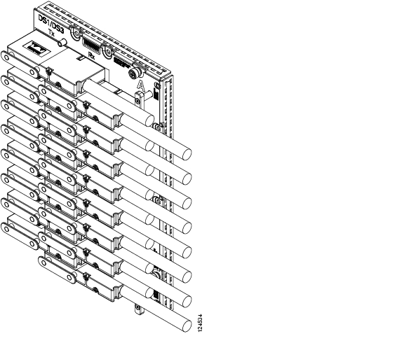
Figure 21-1 shows a UBIC-H with cables installed in all connectors.
Figure 21-1 Fully Cabled UBIC-H (A-Side)
Step 5
Note
Step 6
DLP-A442 Verify Pass-Through Circuits
Step 1
Step 2
Step 3
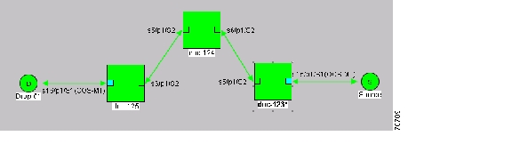
Figure 21-2 Verifying Pass-Through STSs
Step 4
Step 5
Step 6
DLP-A443 Install the Fiber Clip on 15454_MRC-12 Cards
Note
Step 1
Step 2
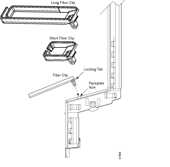
Figure 21-3 Installing the Fiber Clip
Step 3
Step 4
DLP-A444 Provision a PPM on the MRC-12 Card
Step 1
Step 2
Step 3
Step 4
•
•
Step 5
Step 6
Step 7
Step 8
Step 9
Step 10
DLP-A445 Provision the Optical Line Rate on the MRC-12 Card
Step 1
Step 2
Step 3
Step 4
•
•
Step 5
Step 6
Step 7
Step 8
DLP-A446 Change the Optical Line Rate on the MRC-12 Card
Step 1
Step 2
Step 3
Step 4
Step 5
Step 6
Step 7
DLP-A447 Delete a PPM from the MRC-12 or OC192-XFP Card
Step 1
You cannot delete a port on a PPM if it is in service, part of a protection group, has a communications channel termination in use, is used as a timing source, has circuits, or has overhead circuits. As needed, complete the following procedures and task:
•
•
•
•
•
Step 2
Step 3
Step 4
a.
b.
c.
Step 5
•
•
Step 6
Step 7
DLP-A448 Convert DS3XM-6 or DS3XM-12 Cards From 1:1 to 1:N Protection
Note
Step 1
Step 2
Step 3
a.
b.
The working slot should change to Working/Active and the protect slot should change to Protect/Standby. If they fail to change, do not continue. Troubleshoot the working card and slot to determine why the card cannot carry working traffic.
Step 4
Step 5
Step 6
Step 7
Step 8
Step 9
Note
Step 10
Step 11
Step 12
Step 13
Step 14
Step 15
Step 16
Step 17
Step 18
Step 19
Step 20
Step 21
Step 22
The protection group should appear in the Protection Groups list on the Protection subtab.
Step 23
DLP-A449 Set Up SNMP for a GNE
Step 1
Step 2
Step 3
•
•
Note
•
•
Step 4
Step 5
Step 6
Step 7
Step 8
Note
For more information about the SNMP proxy feature, refer to the "SNMP" chapter of the Cisco ONS 15454 Reference Manual.
Step 9
Step 10
DLP-A450 Set Up SNMP for an ENE
Step 1
Step 2
Step 3
•
•
Note
•
•
Step 4
Step 5
Step 6
Step 7
Step 8
Note
For more information about the SNMP proxy feature, refer to the "SNMP" chapter of the Cisco ONS 15454 Reference Manual.
Step 9
Step 10
a.
b.
•
•
The SNMP proxy directs SNMP traps in the following general order: ENE > RELAY A > RELAY B > RELAY C > NMS. The following parameters also apply:
•
•
•
Step 11
Step 12
Step 13
DLP-A451 Format and Enter NMS Community String for SNMP Command or Operation
Step 1
Note
Step 2
•
allviews{192.168.7.4,,,net7node4}If "allviews" is a valid community name value at the proxy-enabled SNMP agent (the GNE), the GNE is expected to forward the PDU to 192.168.7.4 at Port 161. The outgoing PDU will have "net7node4" as the community name. This is the valid community name for the ENE with address 192.168.7.4.
•
allviews{192.168.7.99,,,enter7{192.168.9.6,161,,net9node6}}If "allviews" is a valid community name value at the proxy-enabled GNE, the GNE is expected to forward the PDU to 192.168.7.99 at the default port (Port 161) with a community name of "enter7{192.168.9.6,161,,net9node6}". The system with the address 192.168.7.99 (the NE between the GNE and ENE) forwards this PDU to 192.168.9.6 at Port 161 (at the ENE) with a community name of "net9node6". The community name "enter7" is valid for the NE between the GNE and the ENE and "net9node6" is a valid community name for the ENE.
Step 3
Step 4
Step 5
Step 6
Step 7
DLP-A452 Create a VLAN
Purpose
This task creates a new VLAN.
Tools/Equipment
None
Prerequisite Procedures
See Chapter 6, "Create Circuits and VT Tunnels" for circuit creation procedures.
Required/As Needed
As needed
Onsite/Remote
Onsite or remote
Security Level
Provisioning or higher
Step 1
Step 2
Step 3
Step 4
•
•
•
Step 5
Step 6
Step 7
DLP-A453 Delete a Server Trail
Purpose
This task deletes a server trail.
Tools/Equipment
None
Prerequisite Procedures
NTP-A326 Create a Server Trail, page 6-93
Required/As Needed
As needed
Onsite/Remote
Onsite or remote
Security Level
Provisioning or higher
Step 1
Step 2
Step 3
Step 4
Step 5
Step 6
DLP-A454 View the BLSR STS Squelch Table
Step 1
a.
b.
c.
Step 2
a.
b.
c.
d.
e.
Step 3
•
•
•
•
•
•
•
•
•
Note
Step 4
DLP-A455 View the BLSR VT Squelch Table
Step 1
a.
b.
c.
Step 2
a.
b.
c.
d.
e.
Step 3
Note
•
•
•
Step 4
DLP-A456 Configure the Node for RADIUS Authentication
Purpose
This task allows you to configure a node for Remote Authentication Dial In User Service (RADIUS) authentication. RADIUS validates remote users who are attempting to connect to the network.
Tools/Equipment
None
Prerequisite procedures
DLP-A60 Log into CTC, page 17-68
Before configuring the node for RADIUS authentication, you must first add the node as a network device on the RADIUS server. Refer to the User Guide for Cisco Secure ACS for Windows Server for more information about configuring a RADIUS server.
Required/As needed
As needed
Onsite/Remote
Onsite or remote
Security Level
Superuser
Caution
Note
shell:priv-lvl=N, where N is:
0 for Retrieve User
1 for Maintenance User
2 for Provisioning User
3 for Super User.
Step 1
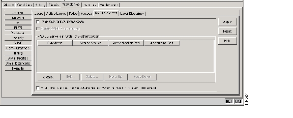
Figure 21-4 RADIUS Server Tab
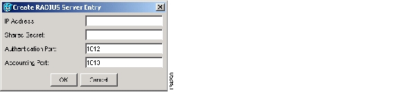
Step 2
Figure 21-5 Create RADIUS Server Entry Window
Step 3
The GNE passes authentication requests from the ENEs in its network to the RADIUS server, which grants authentication if the GNE is listed as a client on the server.
Caution
Step 4
Step 5
Step 6
Step 7
Note
Step 8
Step 9
Step 10
Step 11
Step 12
Step 13
Step 14
Step 15
DLP-A457 Grant Superuser Privileges to a Provisioning User
Step 1
Step 2
Step 3
Note
Step 4
A pencil icon will appear next to the default name that will be changed as a result of editing the defaults file.
Note
Step 5
DLP-A459 Change Optics Thresholds Settings for OC-192 and MRC-12 Cards
Note
Step 1
Step 2
Note
Step 3
Step 4
Step 5
DLP-A460 Reset a Traffic Card Using CTC
Purpose
This task resets an optical, electrical, E-Series Ethernet, G-Series Ethernet, ML-Series Ethernet, or CE-1000-4 Ethernet card in CTC. The CE100T-8 Ethernet card has unique reset tasks; see the "DLP-A54 Hard-Reset a CE-100T-8 Card Using CTC" task on page 17-66 or the "DLP-A224 Soft-Reset a CE-100T-8 Card Using CTC" task on page 19-17 for more information.
Tools/Equipment
None
Prerequisite Procedures
Required/As Needed
As needed
Onsite/Remote
Onsite or remote
Security Level
Superuser
Note
Caution
Step 1
Step 2
Step 3
Step 4
DLP-A461 Preprovision an SFP or XFP Device
Purpose
This task preprovisions SFPs/XFPs on the MRC-12 and OC192-XFP cards. The SFPs/XFPs are referred to as PPMs in CTC. Cisco-approved OC-3, OC-12, OC-48, OC-192 and multirate PPMs are compatible with the ONS 15454. See Table 21-9 for a list.
Tools/Equipment
None
Prerequisite Procedures
Required/As Needed
As needed
Onsite/Remote
Onsite or remote
Security Level
None
Note
Note
Step 1
a.
b.
c.
Step 2
Step 3
Step 4
Step 5
•
•
Step 6
Step 7
Step 8
Step 9
Step 10
Step 11
DLP-A462 View and Terminate Active Logins
Step 1
•
•
•
•
•
•
Step 2
Step 3
Step 4
DLP-A463 Roll the Source or Destination of One Optical Circuit
Step 1
Step 2
Step 3
Step 4
Step 5
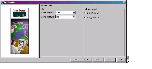
a.
b.
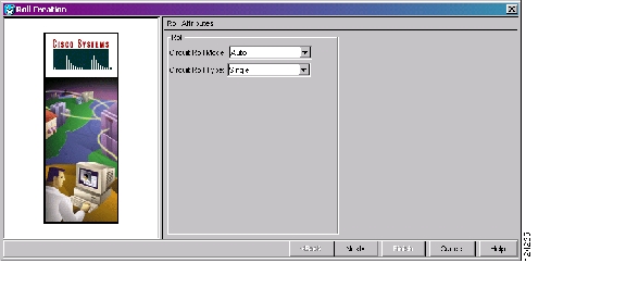
Figure 21-6 Selecting Single Roll Attributes
Step 6
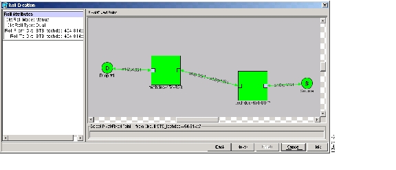
Step 7
This facility is the fixed location in the cross-connect involved in the roll process. The identifier appears in the text box below the graphic image. The facility that is not selected is the Roll From path. The Roll From path is deleted after the roll is completed.
Figure 21-7 Selecting a Path
Step 8
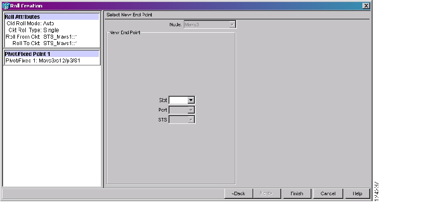
Step 9
Figure 21-8 Selecting a New Endpoint
Step 10
Step 11
•
•
•
Note
•
Note
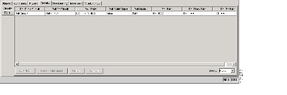
Figure 21-9 Viewing the Rolls Tab
Step 12
Step 13
Step 14
DLP-A464 Roll One Cross-Connect from an Optical Circuit to a Second Optical Circuit
Purpose
This task reroutes a cross-connect on one circuit onto another circuit, resulting in a new destination.
Tools/Equipment
None
Prerequisite Procedures
DLP-A60 Log into CTC, page 17-68
A156 Delete a Section DCC Termination for the ports involved in the roll
Required/As Needed
As needed
Onsite/Remote
Onsite or remote
Security Level
Provisioning or higher
Step 1
Step 2
Step 3
The circuits must have a DISCOVERED status; in addition, they must be the same size and direction for you to begin a roll. The planned Roll To circuit must not carry traffic. The Roll To facility should be DCC connected to the source node of the Roll To circuit.
Step 4
Step 5
a.
b.
c.
Figure 21-10 Selecting Roll Attributes for a Single Roll onto a Second Circuit
Step 6
Step 7
This facility is the fixed location in the cross-connect involved in the roll process. The identifier appears in the text box below the graphic image. The facility that is not selected is the Roll From path. The Roll From path is deleted after the roll is completed.
Step 8
Step 9
Step 10
The statuses of the Roll From and Roll To circuits change from DISCOVERED to ROLL_PENDING in the Circuits tab.
Step 11
•
•
•
Note
•
Step 12
Step 13
The roll is cleared from the Rolls tab and the new rolled circuit on Circuits tab returns to the DISCOVERED status.
Step 14
DLP-A465 Roll Two Cross-Connects on One Optical Circuit Using Automatic Routing
Step 1
Step 2
Step 3
Step 4
Step 5
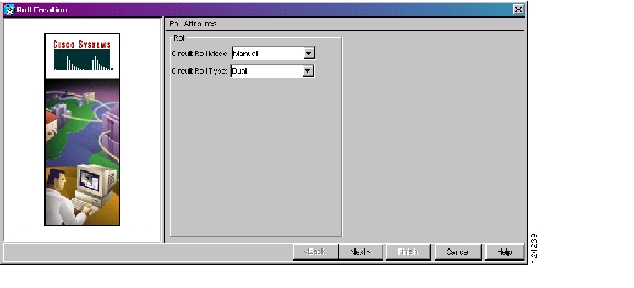
a.
b.
Figure 21-11 Selecting Dual Roll Attributes
Step 6
Step 7
This path is a fixed point in the cross connection involved in the roll process. The path identifier appears in the text box below the graphic image. The path that is not selected contains the Roll From path. The Roll From path is deleted after the roll is completed.
Step 8
Step 9
•
•
Step 10
The path that is not selected is the Roll From path. The Roll From path is deleted after the roll is completed. The path identifier appears in the text box below the graphic image.
Step 11
Step 12
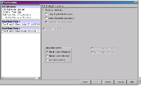
•
•
Figure 21-12 Setting Roll Routing Preferences
Step 13
•
•
•
Step 14
•
•
•
Step 15
a.
b.
c.
d.
Step 16
a.
b.
Caution
Step 17
In the Circuits tab, verify that a new circuit appears. This circuit is the Roll To circuit. It is designated with the Roll From circuit name appended with ROLL**.
Step 18
•
•
•
Note
Note
•
Step 19
Note
Step 20
Step 21
DLP-A466 Roll Two Cross-Connects on One Optical Circuit Using Manual Routing
Step 1
Step 2
Step 3
Step 4
Step 5
a.
b.
Step 6
Step 7
This path is a fixed point in the cross-connect involved in the roll process. The path identifier appears in the text box below the graphic image. The path that is not selected contains the Roll From path. The Roll From path is deleted after the roll is completed.
Step 8
Step 9
•
•
Step 10
The path that is not selected is the Roll From path. The Roll From path is deleted after the roll is complete. The path identifier appears in the text box below the graphic image.
Step 11
Step 12
Step 13
•
•
Step 14
•
•
•
Step 15
The green arrows pointing from the source node to other network nodes indicate spans that are available for routing the circuit.
Step 16
Caution
Step 17
This circuit is the Roll To circuit. It is designated with the Roll From circuit name appended with ROLL**.
Step 18
•
•
•
Note
•
Step 19
Note
Step 20
Step 21
DLP-A467 Roll Two Cross-Connects from One Optical Circuit to a Second Optical Circuit
Step 1
Step 2
Step 3
The Roll From path will be on one circuit and the Roll To path will be on the other circuit. The circuits must have a DISCOVERED status and must be the same size and direction for you to begin a roll. The planned Roll To circuit must not carry traffic. The first Roll To path must be DCC-connected to the source node of the Roll To circuit, and the second Roll To path must be DCC-connected to the destination node of the Roll To circuit.
Step 4
Step 5
a.
b.
c.
Step 6
Step 7
This path is a fixed point in the cross-connect involved in the roll process. The path identifier appears in the text box below the graphic image. The path that is not selected contains the Roll From path. The Roll From path is deleted after the roll is completed.
Step 8
Step 9
•
•
The circuit status for the Roll From path changes from DISCOVERED to ROLL PENDING.
Step 10
The path that is not selected is the Roll From path. The Roll From path is deleted after the roll is completed. The path identifier appears in the text box below the graphic image.
Step 11
Caution
Step 12
Step 13
•
•
•
Note
•
Step 14
Note
Step 15
Step 16
DLP-A468 Delete a Roll
Purpose
This task deletes a roll. Use caution when selecting this option, traffic might be affected. Delete a roll only if it cannot be completed or cancelled in normal ways. Circuits might have a PARTIAL status when this option is selected. See Table 21-2 for a description of circuit statuses.
Tools/Equipment
None
Prerequisite Procedures
DLP-A60 Log into CTC, page 17-68
Required/As Needed
As needed
Onsite/Remote
Onsite or remote
Security Level
Provisioning or higher
Step 1
Step 2
Step 3
Step 4
Step 5
Step 6
DLP-A469 Install a GBIC or SFP/XFP Device
Purpose
This task installs GBICs (required for E-Series Ethernet, G-Series Ethernet, CE-1000-4, and FC_MR-4 cards) and SFPs/XFPs (required for ML1000-2, ML100X-8, MXP, MRC-12, and OC192-XFP cards) and attaches fiber to the devices. GBICs, SFPs, and XFPs are hot-swappable input/output devices that plug into a traffic card port to link the port with the fiber-optic network. For a description of SFP/XFP devices on transponder or muxponder cards, refer to the Cisco ONS 15454 DWDM Reference Manual.
Tools/Equipment
For the E1000-2-G, G1K-4, CE-1000-4, or FC_MR-4 cards, use the SX, LX, ZX, or DWDM GBICs shown in Table 21-8.
For the ML1000-2, ML100X-8, MRC-12, and OC192-XFP cards, use the SFPs and XFPs shown in Table 21-9.
Prerequisite Procedures
One or more of the following, depending on the card where you will install the GBIC or SFP/XFP device:
•
•
Required/As Needed
As needed
Onsite/Remote
Onsite
Security Level
None
Warning
Warning
Note
Note
Note
Step 1
Step 2
Table 21-8 shows the available GBICs.
Note
Table 21-9 shows the available SFPs and XFPs.
Table 21-9 Available SFPs and XFPs
1000BaseSX
ML1000-2
Short reach
Multimode fiber up to 550 m long
15454E-SFP-LC-SX=
1000BaseLX
Long reach
Single-mode fiber up to 5 km long
15454E-SFP-LC-LX=
1000BaseFX
ML100X-8
Short reach
1310 nm multimode fiber up to 2 km long
ONS-SE-100-FX
1000BaseLX-10
Intermediate reach
1310 nm, single mode fiber, up to 15 km long
ONS-SE-100-LX10
OC-48 SR
MRC-12
Short reach
1310-nm single-mode fiber up to 2 km long
ONS-SI-2G-S1
OC-48 IR1
Intermediate reach
1310-nm single-mode fiber, up to 15 km long
ONS-SI-2G-I1
OC-48 LR1
Long reach
1310-nm single-mode fiber up to 40 km long
ONS-SI-2G-L1
OC-48 LR2
Long reach
1550-nm single-mode fiber up to 80 km long
ONS-SI-2G-L2
OC-48 LR2 DWDM
Long reach
1530.33 to 1560.61 nm single-mode fiber up to 120 km long
ONS-SC-2G-30.3 through
ONS-SC-2G-60.6OC-3/OC-12 IR1 dual rate
Intermediate reach
1310-nm single-mode fiber up to 15 km long
ONS-SI-622-I1
OC-12 LR1
Long reach
1310-nm single-mode fiber up to 40 km long
ONS-SI-622-L1
OC-12 LR2
Long reach
1550-nm single-mode fiber up to 80 km long
ONS-SI-622-L2
OC-12 CWDM
Long reach
1470 to 1610 nm single-mode fiber up to 80 km long
ONS-SE-622-1470 through
ONS-SE-622-1610OC-3 IR1
Intermediate reach
1310-nm single-mode fiber up to 15 km long
ONS-SI-155-I1
OC-3 LR1
Long reach
1310-nm single-mode fiber up to 40 km long
ONS-SI-155-L1
OC-3 LR2
Long reach
1550-nm single-mode fiber up to 80 km long
ONS-SI-155-L2
OC-3 CWDM
Long reach
1470 to 1610 nm single-mode fiber up to 80 km long
ONS_SE-155-1470 through
ONS-SE-155-1610OC-192 SR1
OC192SR1/
STM64IO Short Reach1Short reach
1310-nm single-mode fiber up to 10 km long
ONS-XC-10G-S1
OC-192 SR1, IR1, LR2
OC192/
STM64 Any Reach1Short reach
1310-nm single-mode fiber up to 10 km long
ONS-XC-10G-S1
Intermediate reach
1550-nm single-mode fiber up to 15 km long
ONS-XC-10G-I2
Long reach
1550-nm single-mode fiber up to 80 km long
ONS-XC-10G-L2
1 CTC refers to this card as OC192-XFP
Note
Step 3
•
•
•
Step 4
a.
Note
b.
c.
d.
Step 5
a.
b.
c.
d.
The click indicates that the GBIC is locked into the slot.
e.
f.
Step 6
a.
b.
c.
SFPs and XFPs must be provisioned in CTC. If you installed a multirate PPM, complete the "DLP-A444 Provision a PPM on the MRC-12 Card" task. (Single-rate XFPs do not need to be provisioned in CTC.)
Step 7
DLP-A470 Remove GBIC or SFP/XFP Devices
Warning
Step 1
Step 2
a.
b.
Step 3
a.
b.
c.
Step 4
a.
b.
c.
d.
Step 5
DLP-A489 Cancel a Roll
Purpose
This task cancels a roll. When the roll mode is Manual, you can only cancel a roll before you click the Complete button. When the roll mode is Auto, cancelling a roll is only allowed before a good signal is detected by the node or before clicking the Force Valid Signal button. A dual or single roll can be cancelled before the roll state changes to ROLL_COMPLETED.
Tools/Equipment
None
Prerequisite Procedures
DLP-A60 Log into CTC, page 17-68
Required/As Needed
As needed
Onsite/Remote
Onsite or remote
Security Level
Provisioning or higher
Caution
Step 1
Step 2
Step 3
Step 4
DLP-A495 Consolidate Links in Network View
Note
Step 1
Step 2
•
•
•
•
•
•
•
Step 3
Step 4
a.
b.
c.
d.
Step 5
a.
b.
Note
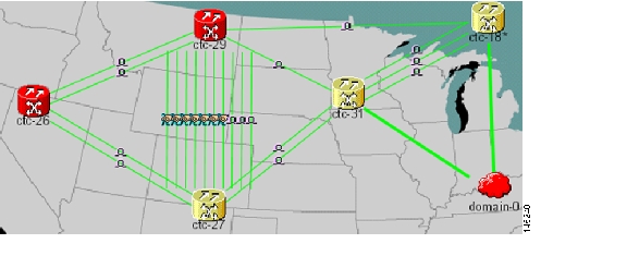
Figure 21-13 shows the network view with unconsolidated DCC and PPC links.
Figure 21-13 Unconsolidated Links in the Network View
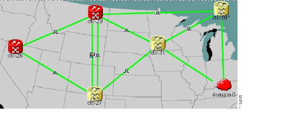
Figure 21-14 shows a network view with globally consolidated links.
Figure 21-14 Consolidated Links in the Network View
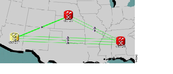
Figure 21-15 shows a network view with local DCC link consolidation between two nodes.
Figure 21-15 Network View with Local Link Consolidation
Step 6
Step 7
a.
b.
Step 8
Step 9
a.
The link classes that appear in the Link Filter dialog are determined by the Network Scope you choose in the network view ( Table 21-10).
Table 21-10 Link Classes By Network Scope
ALL
DCC, GCC, OTS, PPC, Server Trail
DWDM
GCC, OTS, PPC
TDM
DCC, PPC, Server Trail
b.
c.
Step 10
DLP-A498 Switch Between TDM and DWDM Network Views
Step 1
Step 2
•
•
•
Note
Step 3
![]()
![]()
![]()
![]()
![]()
![]()
![]()
![]()
Posted: Mon Oct 29 05:04:29 PDT 2007
All contents are Copyright © 1992--2007 Cisco Systems, Inc. All rights reserved.
Important Notices and Privacy Statement.