|
|

Table Of Contents
DLP-A111 Changing the Maximum Number of Session Entries for Alarm History
DLP-A112 Display Alarms and Conditions Using Time Zone
DLP-A117 Apply Alarm Profiles to Cards and Nodes
DLP-A121 Enable/Disable Pointer Justification Count Performance Monitoring
DLP-A122 Enable/Disable Intermediate Path Performance Monitoring
DLP-A124 Refresh PM Counts at 15-Minute Intervals
DLP-A125 Refresh PM Counts at One-Day Intervals
DLP-A126 View Near-End PM Counts
DLP-A127 View Far-End PM Counts
DLP-A129 Reset Current PM Counts
DLP-A137 Provision Path Trace on OC-N Ports
DLP-A140 Change the Node Name, Date, Time, and Contact Information
DLP-A142 Modify a Static Route
DLP-A143 Delete a Static Route
DLP-A145 Change the Network View Background Color
DLP-A150 Modify a 1:1 Protection Group
DLP-A152 Modify a 1:N Protection Group
DLP-A154 Modify a 1+1 Protection Group
DLP-A155 Delete a Protection Group
DLP-A156 Delete a Section DCC Termination
DLP-A157 Change the Node Timing Source
DLP-A158 Change User Password and Security Level on a Single Node
DLP-A159 Delete a User from a Single Node
DLP-A160 Change User Password and Security Level on Multiple Nodes
DLP-A161 Delete a User from Multiple Nodes
DLP-A163 Delete SNMP Trap Destinations
DLP-A165 Change Line and Threshold Settings for a DS1-14 or DS1N-14 Card
DLP-A166 Change Line and Threshold Settings for a DS3-12 or DS3N-12 Card
DLP-A167 Change Line and Threshold Settings for a DS3E-12 or DS3N-12E Card
DLP-A168 Change Line and Threshold Settings for the DS3XM-6 Card
DLP-A169 Change Line and Threshold Settings for the EC1-12 Card
DLP-A171 Change Threshold Settings for OC-N Cards
DLP-A172 Change an Optical Port to SDH
DLP-A176 Convert DS1-14 Cards From 1:1 to 1:N Protection
DLP-A177 Convert DS3-12 Cards From 1:1 to 1:N Protection
DLP-A178 Convert DS3-12E Cards From 1:1 to 1:N Protection
DLP-A189 Verify that a 1+1 Working Slot is Active
DLP-A194 Clear a BLSR Force Ring Switch
DLP-A195 Verify Timing in a Reduced Ring
DLP-A196 Delete a BLSR from a Single Node
DLP-A197 Initiate a Path Protection Force Switch
DLP-A198 Clear a Path Protection Force Switch
DLPs A100 to A199
Note
The terms "Unidirectional Path Switched Ring" and "UPSR" may appear in Cisco literature. These terms do not refer to using Cisco ONS 15xxx products in a unidirectional path switched ring configuration. Rather, these terms, as well as "Path Protected Mesh Network" and "PPMN," refer generally to Cisco's path protection feature, which may be used in any topological network configuration. Cisco does not recommend using its path protection feature in any particular topological network configuration.
DLP-A111 Changing the Maximum Number of Session Entries for Alarm History
Step 1
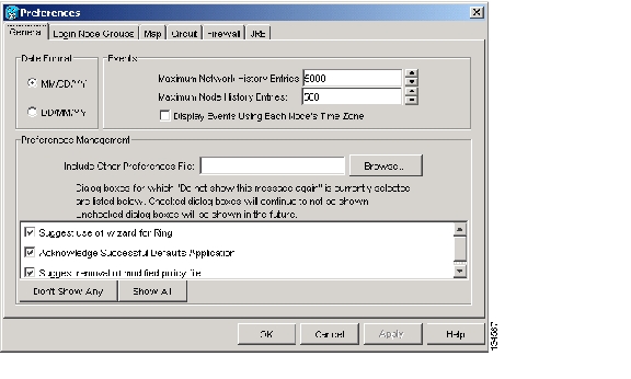
The Cisco Transport Controller (CTC) Preferences dialog box appears ( Figure 18-1).
Figure 18-1 CTC Preferences Dialog Box
Step 2
Step 3
Note
Note
Step 4
DLP-A112 Display Alarms and Conditions Using Time Zone
Step 1
The CTC Preferences dialog box appears ( Figure 18-1).
Step 2
Step 3
Step 4
DLP-A113 Synchronize Alarms
Step 1
Step 2
This button causes CTC to retrieve a current alarm summary for the card, node, or network. This step is optional because CTC updates the Alarms window automatically as raise/clear messages arrive from the node.
Note
Step 3
DLP-A114 View Conditions
Step 1
Step 2
The Retrieve button requests the current set of fault conditions from the node, card, or network. The window is not updated when events change on the node. You must click Retrieve to see any changes.
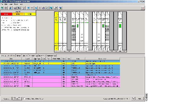
Figure 18-2 Node View Conditions Window
Conditions include all fault conditions raised on the node, whether or not they are reported.
Note
Events that are reported as Major (MJ), Minor (MN), or Critical (CR) severities are alarms. Events that are reported as Not-Alarmed (NA) are conditions. Conditions that are not reported at all are marked Not-Reported (NR) in the Conditions window severity column.
Conditions that have a default severity of Critical (CR), Major (MJ), Minor (MN), or Not-Alarmed (NA) but are not reported due to exclusion or suppression are shown as NR in the Conditions window.
Note
Current conditions are shown with the severity chosen in the alarm profile, if used. For more information about alarm profiles, see the "NTP-A71 Create, Download, and Assign Alarm Severity Profiles" procedure on page 8-6.
Note
Step 3
An exclusion rule eliminates all lower-level alarms or conditions that originate from the same cause. For example, a fiber break may cause an LOS alarm, an AIS condition, and an SF condition. If you check the Exclude Same Root Cause check box, only the LOS alarm will appear. According to Telcordia, exclusion rules apply to a query of "all conditions from a node."
Step 4
DLP-A117 Apply Alarm Profiles to Cards and Nodes
Purpose
This task applies a custom or default alarm profile to cards or nodes.
Tools/Equipment
None
Prerequisite Procedures
DLP-A518 Create a New or Cloned Alarm Severity Profile, page 22-9
Required/As Needed
As needed
Onsite/Remote
Onsite or remote
Security Level
Provisioning or higher
Step 1
Figure 18-3 Node View Alarm Profile
Step 2
a.
b.
c.
Step 3
a.
b.
c.
Step 4
Step 5
DLP-A121 Enable/Disable Pointer Justification Count Performance Monitoring
Step 1
Step 2
See Table 18-1 for a list of line terminating equipment (LTE) cards.
Step 3
Step 4
•
•
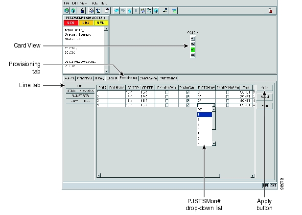
Figure 18-4 Enabling or Disabling Pointer Justification Count Parameters
Step 5
Step 6
Step 7
Note
Step 8
DLP-A122 Enable/Disable Intermediate Path Performance Monitoring
Note
Note
Step 1
See Table 18-1 for a list of OC-N LTE cards.
Step 2
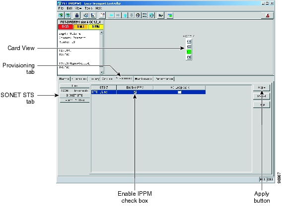
Figure 18-5 SONET STS Tab for Enabling or Disabling IPPM
Step 3
•
•
Step 4
Step 5
Step 6
DLP-A124 Refresh PM Counts at 15-Minute Intervals
Step 1
Step 2
Step 3
Step 4
Step 5
Each monitored performance parameter has corresponding threshold values for the current time period. If the value of the counter exceeds the threshold value for a particular 15-minute interval, a threshold crossing alert (TCA) is raised. The number represents the counter value for each specific performance monitoring parameter.
Step 6
Note
Step 7
DLP-A125 Refresh PM Counts at One-Day Intervals
Step 1
Step 2
Step 3
Step 4
Step 5
Each monitored performance parameter has corresponding threshold values for the current time period. If the value of the counter exceeds the threshold value for a particular 1-day interval, a threshold crossing alert (TCA) is raised. The number represents the counter value for each specific performance monitoring parameter.
Step 6
Note
Step 7
DLP-A126 View Near-End PM Counts
Step 1
Step 2
Step 3
Step 4
Step 5
Step 6
Step 7
DLP-A127 View Far-End PM Counts
Step 1
Step 2
Step 3
Step 4
Step 5
Step 6
Step 7
DLP-A129 Reset Current PM Counts
Step 1
Step 2
Step 3
Note
Step 4
Step 5
DLP-A131 Search for Circuits
Step 1
•
•
•
Step 2
Step 3
Step 4
Step 5
•
•
•
•
Step 6
Step 7
Step 8
DLP-A137 Provision Path Trace on OC-N Ports
Purpose
This task monitors a path trace on OC-N ports within the circuit path.
Tools/Equipment
The OC-N ports you want to monitor must be on OC-N cards capable of receiving path trace. See Table 19-3 on page 19-44.
Prerequisite Procedures
DLP-A264 Provision a J1 Path Trace on Circuit Source and Destination Ports, page 19-43
Required/As Needed
As needed
Onsite/Remote
Onsite or remote
Security Level
Provisioning or higher
Step 1
Step 2
Step 3
Step 4
Step 5
Note
Step 6
•
•
Step 7
Step 8
Step 9
DLP-A140 Change the Node Name, Date, Time, and Contact Information
Note
Step 1
Step 2
•
•
•
•
•
Note
•
•
•
•
•
•
•
See the "NTP-A25 Set Up Name, Date, Time, and Contact Information" procedure on page 4-4 for detailed field descriptions.
Step 3
Step 4
DLP-A142 Modify a Static Route
Purpose
This task modifies a static route on an ONS 15454.
Tools/Equipment
None
Prerequisite Procedures
DLP-A60 Log into CTC, page 17-65
Required/As Needed
As needed
Onsite/Remote
Onsite or remote
Security Level
Provisioning or higher
Step 1
Step 2
Step 3
Step 4
Step 5
•
•
•
See the "DLP-A65 Create a Static Route" task on page 17-72 for detailed field descriptions.
Step 6
Step 7
DLP-A143 Delete a Static Route
Purpose
This task deletes an existing static route on an ONS 15454.
Tools/Equipment
None
Prerequisite Procedures
DLP-A60 Log into CTC, page 17-65
Required/As Needed
As needed
Onsite/Remote
Onsite or remote
Security Level
Provisioning or higher
Step 1
Step 2
Step 3
Step 4
Step 5
DLP-A144 Disable OSPF
Purpose
This task disables the Open Shortest Path First (OSPF) routing protocol process for an ONS 15454 LAN.
Tools/Equipment
None
Prerequisite Procedures
DLP-A60 Log into CTC, page 17-65
DLP-A250 Set Up or Change Open Shortest Path First Protocol, page 19-33
Required/As Needed
As needed
Onsite/Remote
Onsite or remote
Security Level
Provisioning or higher
Step 1
Step 2
Step 3
Step 4
DLP-A145 Change the Network View Background Color
Note
Step 1
Step 2
Step 3
Step 4
Step 5
Step 6
DLP-A148 Create Domain Icons
Note
Step 1
Step 2
Step 3
Step 4
Step 5
DLP-A149 Manage Domain Icons
Purpose
This task manages CTC network view domain icons.
Tools/Equipment
None
Prerequisite procedures
DLP-A60 Log into CTC, page 17-65
Required/As needed
As needed
Onsite/Remote
Onsite or remote
Security Level
Provisioning or higher
Note
Step 1
Step 2
Step 3
DLP-A150 Modify a 1:1 Protection Group
Purpose
This task modifies a 1:1 protection group for electrical (DS-1, DS-3, EC-1, and DS3XM) cards.
Tools/Equipment
None
Prerequisite Procedures
DLP-A71 Create a 1:1 Protection Group, page 17-77
Required/As Needed
As needed
Onsite/Remote
Onsite or remote
Security Level
Provisioning or higher
Step 1
Step 2
Step 3
•
•
•
Step 4
Note
Step 5
DLP-A152 Modify a 1:N Protection Group
Purpose
This task modifies a 1:N protection group for DS-1 and DS-3 cards.
Tools/Equipment
None
Prerequisite Procedures
DLP-A72 Create a 1:N Protection Group, page 17-79
Required/As Needed
As needed
Onsite/Remote
Onsite or remote
Security Level
Provisioning or higher
Step 1
Step 2
Step 3
Step 4
•
•
•
•
See the "DLP-A72 Create a 1:N Protection Group" task on page 17-79 for field descriptions.
Step 5
Note
Step 6
DLP-A154 Modify a 1+1 Protection Group
Purpose
This task modifies a 1+1 protection group for any optical port (OC-3, OC-12, OC-12 IR, OC-48, OC-48AS, and OC-192).
Tools/Equipment
None
Prerequisite Procedures
DLP-A73 Create a 1+1 Protection Group, page 17-80
Required/As Needed
As needed
Onsite/Remote
Onsite or remote
Security Level
Provisioning or higher
Step 1
Step 2
Step 3
•
•
•
•
See the "DLP-A73 Create a 1+1 Protection Group" task on page 17-80 for field descriptions.
Step 4
Step 5
DLP-A155 Delete a Protection Group
Step 1
Step 2
Step 3
Step 4
Step 5
DLP-A156 Delete a Section DCC Termination
Step 1
Step 2
Step 3
Step 4
DLP-A157 Change the Node Timing Source
Caution
Step 1
Step 2
•
Note
•
•
•
•
See the "DLP-A69 Set Up SONET External or Line Timing" task on page 17-74 for field descriptions.
Step 3
Note
•
•
•
•
•
•
•
•
Step 4
Note
•
•
•
Step 5
Step 6
DLP-A158 Change User Password and Security Level on a Single Node
Purpose
This task changes settings for an existing user at one node.
Tools/Equipment
None
Prerequisite Procedures
Required/As Needed
As needed
Onsite/Remote
Onsite or remote
Security Level
Superuser
Step 1
Step 2
Step 3
•
•
•
See the "NTP-A30 Create Users and Assign Security" procedure on page 4-4 for field descriptions.
Step 4
Note
Step 5
DLP-A159 Delete a User from a Single Node
Purpose
This task deletes an existing user from a single node.
Tools/Equipment
None
Prerequisite Procedures
Required/As Needed
As needed
Onsite/Remote
Onsite or remote
Security Level
Superuser
Note
Note
Step 1
Step 2
Step 3
Step 4
Step 5
Step 6
DLP-A160 Change User Password and Security Level on Multiple Nodes
Note
Step 1
Step 2
Step 3
Step 4
•
•
•
See the "DLP-A75 Create a New User on Multiple Nodes" task on page 17-82 for field descriptions.
Step 5
Step 6
Step 7
Step 8
DLP-A161 Delete a User from Multiple Nodes
Purpose
This task deletes an existing user from multiple nodes.
Tools/Equipment
None
Prerequisite Procedures
Required/As Needed
As needed
Onsite/Remote
Onsite or remote
Security Level
Superuser
Note
Note
Step 1
Step 2
Step 3
Step 4
Step 5
Step 6
Step 7
DLP-A163 Delete SNMP Trap Destinations
Step 1
Step 2
Step 3
Step 4
Step 5
DLP-A165 Change Line and Threshold Settings for a DS1-14 or DS1N-14 Card
Step 1
Step 2
Step 3
Note
Step 4
Step 5
Step 6
Table 18-3 describes the values on the Provisioning > Line tabs.
Table 18-3 Line Options for DS1-14 and DS1N-14 Cards
Port #
(Display only) Port number.
1 to 14
Port Name
Sets the port name.
User-defined, up to 32 alphanumeric/special characters. Blank by default.
See the "DLP-A314 Assign a Name to a Port" task on page 20-8.
SF BER
Sets the signal fail bit error rate.
•
•
•
SD BER
Sets the signal degrade bit error rate.
•
•
•
•
•
Line Type
Defines the line framing type.
•
•
•
Line Coding
Defines the DS-1 transmission coding type.
•
•
Line Length
Defines the distance (in feet) from the backplane connection to the next termination point.
•
•
•
•
•
Admin State
Sets the port administrative service state unless network conditions prevent the change.
•
•
•
•
Service State
(Display only) Identifies the autonomously generated state that gives the overall condition of the port. Service states appear in the format: Primary State-Primary State Qualifier, Secondary State.
•
•
•
•
AINS Soak
Sets the automatic in-service soak period.
•
•
Table 18-4 describes the values on the Provisioning > Line Thresholds tabs.
Table 18-5 describes the values on the Provisioning > Elect Path Thresholds tabs.
Table 18-6 describes the values on the Provisioning > SONET Thresholds tabs for the DS-1 cards.
Note
Step 7
DLP-A166 Change Line and Threshold Settings for a DS3-12 or DS3N-12 Card
Step 1
Step 2
Step 3
Note
Step 4
Step 5
Step 6
Table 18-7 describes the values on the Provisioning > Line tabs.
Table 18-7 Line Options for DS3-12 or DS3N-12 Cards
Port
(Display only) Port number.
1 to 12
Port Name
Sets the port name.
User-defined, up to 32 alphanumeric/special characters. Blank by default.
See the "DLP-A314 Assign a Name to a Port" task on page 20-8.
SF BER
Sets the signal fail bit error rate.
•
•
•
SD BER
Sets the signal degrade bit error rate.
•
•
•
•
•
Line Length
Defines the distance (in feet) from backplane connection to the next termination point.
•
•
Admin State
Sets the port administrative service state unless network conditions prevent the change.
•
•
•
•
Service State
(Display only) Identifies the autonomously generated state that gives the overall condition of the port. Service states appear in the format: Primary State-Primary State Qualifier, Secondary State.
•
•
•
•
AINS Soak
Sets the automatic in-service soak period.
Duration of the valid input signal, in hh.mm format, after which the card becomes in service (IS) automatically 0 to 48 hours, 15-minute increments.
Table 18-8 describes the values on the Provisioning > Line Thresholds tabs.
Table 18-9 describes the values on the Provisioning > Elect Path Thresholds tabs.
Table 18-10 describes the values on the Provisioning > SONET Thresholds tabs.
Note
Step 7
DLP-A167 Change Line and Threshold Settings for a DS3E-12 or DS3N-12E Card
Note
Step 1
Step 2
Step 3
Note
Step 4
Step 5
Step 6
Table 18-11 describes the values on the Provisioning > Line tabs.
Table 18-11 Line Options for the DS3-12E and DS3N-12E Cards
Port #
(Display only) Port number.
1 to 12
Port Name
Sets the port name.
User-defined, up to 32 alphanumeric/special characters. Blank by default.
See the "DLP-A314 Assign a Name to a Port" task on page 20-8.
SF BER
Sets the signal fail bit error rate.
•
•
•
SD BER
Sets the signal degrade bit error rate.
•
•
•
•
•
Line Type
Defines the line framing type.
•
•
•
Detected Line Type
(Display only) Displays the detected line type.
•
•
•
•
Line Coding
Defines the DS3E transmission coding type.
B3ZS
Line Length
Defines the distance (in feet) from backplane connection to the next termination point.
•
•
Admin State
Sets the port administrative service state unless network conditions prevent the change.
•
•
•
•
Service State
(Display only) Identifies the autonomously generated state that gives the overall condition of the port. Service states appear in the format: Primary State-Primary State Qualifier, Secondary State.
•
•
•
•
AINS Soak
Sets the automatic in-service soak period.
•
•
Table 18-12 describes the values on the Provisioning > Line Thresholds tabs.
Table 18-13 describes the values on the Provisioning > Elect Path Thresholds tabs.
Table 18-14 describes the values on the Provisioning > SONET Thresholds tabs.
Note
Step 7
DLP-A168 Change Line and Threshold Settings for the DS3XM-6 Card
Note
Step 1
Step 2
Step 3
Note
Step 4
Step 5
Step 6
Table 18-15 describes the values on the Provisioning > Line tabs for the DS3XM-6 cards.
Table 18-15 Line Options for the DS3XM-6 Parameters
Port
(Display only) Sets the port number.
1 to 6
Port Name
Sets the port name.
User-defined, up to 32 alphanumeric/ special characters. Blank by default.
See the "DLP-A314 Assign a Name to a Port" task on page 20-8.
SF BER
Sets the signal fail bit error rate.
•
•
•
SD BER
Sets the signal degrade bit error rate.
•
•
•
•
•
Line Type
Defines the line framing type.
•
•
Line Coding
Defines the DS-1 transmission coding type that is used.
B3ZS
Line Length
Defines the distance (in feet) from backplane connection to the next termination point.
•
•
Admin State
Sets the port administrative service state unless network conditions prevent the change.
•
•
•
•
Service State
(Display only) Identifies the autonomously generated state that gives the overall condition of the port. Service states appear in the format: Primary State-Primary State Qualifier, Secondary State.
•
•
•
•
AINS Soak
Sets the automatic in-service soak period.
•
•
Table 18-16 describes the values on the Provisioning > Line Thresholds tabs for DS3XM-6 cards.
Table 18-17 describes the values on the Provisioning > Elect Path Thresholds tabs for the DS3XM-6 cards.
Table 18-18 describes the values on the Provisioning > SONET Thresholds tabs for the DS3XM-6 cards.
Note
Step 7
DLP-A169 Change Line and Threshold Settings for the EC1-12 Card
Step 1
Step 2
Step 3
Note
Note
Step 4
Step 5
Step 6
Table 18-19 describes the values on the Line tab for the EC1-12 card.
Table 18-19 Line Options for the EC1-12 Card
Port
(Display only) Port number.
1 to 12
Port Name
(Optional) Sets a name for the port.
User-defined, up to 32 alphanumeric/ special characters. Blank by default.
See the "DLP-A314 Assign a Name to a Port" task on page 20-8.
SF BER
Sets the signal fail bit error rate.
•
•
•
SD BER
Sets the signal degrade bit error rate.
•
•
•
•
•
PJStsMon#
Sets the STS that will be used for pointer justification; if set to zero, no STS is used.
•
•
Line Buildout
Defines the distance (in feet) from backplane to next termination point.
•
•
Rx Equalization
For early EC1-12 card versions, equalization can be turned off if the line length is short or the environment is extremely cold; Rx Equalization should normally be set to On.
•
•
Admin State
Sets the port administrative service state unless network conditions prevent the change.
•
•
•
•
Service State
(Display only) Identifies the autonomously generated state that gives the overall condition of the port. Service states appear in the format: Primary State-Primary State Qualifier, Secondary State.
•
•
•
•
AINS Soak
Sets the automatic in-service soak period.
•
•
Table 18-20 lists the values on the SONET Thresholds tab for EC1-12 cards.
Step 7
DLP-A171 Change Threshold Settings for OC-N Cards
Step 1
Step 2
Step 3
Step 4
Step 5
DLP-A172 Change an Optical Port to SDH
Purpose
This task provisions a port on an OC-N card for SDH. You must put the port in the OOS,MT administrative service state beforing changing the port to SDH.
Tools/Equipment
None
Prerequisite Procedures
DLP-A60 Log into CTC, page 17-65
Required/As Needed
As needed
Onsite/Remote
Onsite or remote
Security Level
Provisioning or higher
Step 1
Step 2
Step 3
Note
Step 4
Step 5
Step 6
DLP-A176 Convert DS1-14 Cards From 1:1 to 1:N Protection
Note
Step 1
Step 2
Step 3
a.
b.
The working slot should change to Working/Active and the protect slot should change to Protect/Standby. If they do not change, do not continue. Troubleshoot the working card and slot to determine why the card cannot carry working traffic.
Step 4
Step 5
Step 6
Step 7
Step 8
Step 9
Note
Step 10
Step 11
Step 12
Step 13
Step 14
Step 15
Step 16
Step 17
Step 18
Step 19
Step 20
Step 21
Step 22
Note
Step 23
Step 24
DLP-A177 Convert DS3-12 Cards From 1:1 to 1:N Protection
Note
Step 1
Step 2
Step 3
a.
b.
The working slot should change to Working/Active and the protect slot should change to Protect/Standby. If they fail to change, do not continue. Troubleshoot the working card and slot to determine why the card cannot carry working traffic.
Step 4
Step 5
Step 6
Step 7
Step 8
Step 9
Note
Step 10
Step 11
Step 12
Step 13
Step 14
Step 15
Step 16
Step 17
Step 18
Step 19
Step 20
Step 21
Step 22
The protection group should appear in the Protection Groups list on the Protection subtab.
Step 23
DLP-A178 Convert DS3-12E Cards From 1:1 to 1:N Protection
Note
Step 1
Step 2
Step 3
a.
b.
The working slot should change to Working/Active and the protect slot should change to Protect/Standby. If they fail to change, do not continue. Troubleshoot the working card and slot to determine why the card cannot carry working traffic.
Step 4
Step 5
Step 6
Step 7
Step 8
Step 9
Note
Step 10
Step 11
Step 12
Step 13
Step 14
Step 15
Step 16
Step 17
Step 18
Step 19
Step 20
Step 21
Step 22
The protection group should appear in the Protection Groups list on the Protection subtab.
Step 23
DLP-A189 Verify that a 1+1 Working Slot is Active
Step 1
Step 2
Step 3
a.
b.
c.
Step 4
Note
Step 5
a.
b.
Step 6
Step 7
DLP-A190 Install a UBIC-V EIA
Caution
Note
Note
Step 1
Step 2
Step 3
Step 4
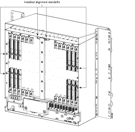
Step 5
Figure 18-6 Installed Alignment Standoffs
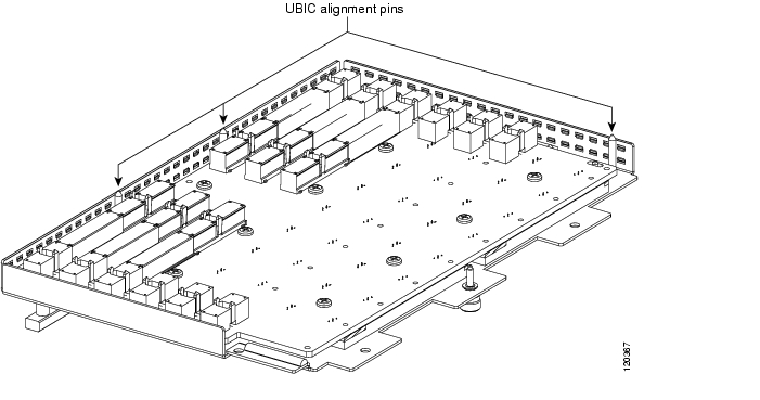
Step 6
Figure 18-7 UBIC-V Alignment Pins
Caution
Step 7
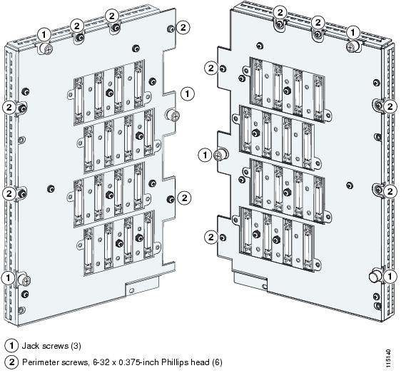
Caution
Figure 18-8 UBIC-V EIA Screw Locations
Figure 18-9 UBIC-V EIA Jack Screw
Step 8
Figure 18-10 shows a UBIC-V EIA installation.
Figure 18-10 Installing the UBIC-V EIA
Step 9
DLP-A191 Delete a Card
Purpose
This task deletes a card from CTC.
Tools/Equipment
None
Prerequisite Procedures
Required/As Needed
As needed
Onsite/Remote
Onsite or remote
Security Level
Provisioning or higher
Step 1
You cannot delete a card if any of the following conditions apply:
•
•
•
•
•
•
Note
Step 2
DLP-A194 Clear a BLSR Force Ring Switch
Purpose
This task removes a Force switch from a BLSR port.
Tools/Equipment
None
Prerequisite Procedures
Required/As Needed
As needed
Onsite/Remote
Onsite
Security Level
Maintenance or higher
Step 1
Step 2
Step 3
Step 4
a.
b.
c.
Step 5
a.
b.
c.
On the BLSR network graphic, a green and a purple span line connects each node. This is the normal display for BLSRs when protection operations are not invoked.
Step 6
Step 7
DLP-A195 Verify Timing in a Reduced Ring
Step 1
Step 2
Step 3
Step 4
a.
b.
c.
Note
Step 5
Step 6
DLP-A196 Delete a BLSR from a Single Node
Step 1
•
•
Step 2
Step 3
Step 4
Step 5
Step 6
DLP-A197 Initiate a Path Protection Force Switch
Caution
Caution
Step 1
Step 2
Step 3
Step 4
Step 5
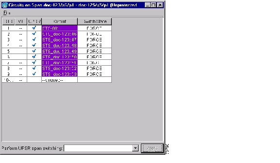
In the Circuits on Span window, the Switch State for all circuits is FORCE. Figure 18-11 shows an example.
Figure 18-11 Circuits on Span Dialog Box with a Force Switch
Note
Step 6
DLP-A198 Clear a Path Protection Force Switch
Purpose
This task clears a Path Protection Force switch.
Tools/Equipment
None
Prerequisite Procedures
Required/As Needed
As needed
Onsite/Remote
Onsite or remote
Security Level
Maintenance or higher
Step 1
Step 2
Step 3
Step 4
Step 5
In the Circuits on Span window, the Switch State for all path protection circuits is CLEAR.
Step 6
![]()
![]()
![]()
![]()
![]()
![]()
![]()
![]()
Posted: Wed Oct 10 03:36:21 PDT 2007
All contents are Copyright © 1992--2007 Cisco Systems, Inc. All rights reserved.
Important Notices and Privacy Statement.