|
|

Table Of Contents
DLP-A412 Install the DCU Shelf Assembly
DLP-A416 View Circuit Information
DLP-A417 View the BLSR Squelch Table
DLP-A418 Install Public-Key Security Certificate
DLP-A421 Provision G-Series Flow Control Watermarks
DLP-A422 Verify BLSR Extension Byte Mapping
DLP-A428 Install Fiber-Optic Cables in a 1+1 Configuration
DLP-A430 View Spanning Tree Information
DLP-A431 Change the JRE Version
DLP-A433 Enable Node Security Mode
DLP-A435 Modify Backplane Port IP Settings
DLP-A436 Disable Node Security Mode
DLP-A437 Change a VCAT Member Service State
DLP-A438 Change General Port Settings for the FC_MR-4 Card
DLP-A439 Change Distance Extension Port Settings for the FC_MR-4 Card
DLP-A440 Change Enhanced FC/FICON Port Settings for the FC_MR-4 Card
DLP-A441 Install Electrical Cables on the UBIC-H EIAs
DLP-A442 Verify Pass-Through Circuits
DLP-A469 Install GBIC or SFP Connectors
DLP-A470 Remove GBIC or SFP Connectors
DLP-A498 Switch Between TDM and DWDM Network Views
DLPs A400 to A499
Note
The terms "Unidirectional Path Switched Ring" and "UPSR" may appear in Cisco literature. These terms do not refer to using Cisco ONS 15xxx products in a unidirectional path switched ring configuration. Rather, these terms, as well as "Path Protected Mesh Network" and "PPMN," refer generally to Cisco's path protection feature, which may be used in any topological network configuration. Cisco does not recommend using its path protection feature in any particular topological network configuration.
DLP-A412 Install the DCU Shelf Assembly
Step 1
Step 2
Step 3
Warning
Step 4
Step 5
DLP-A416 View Circuit Information
Step 1
•
•
•
Note
Step 2
•
•
•
•
•
•
•
•
•
•
•
•
•
–
–
–
Step 3
DLP-A417 View the BLSR Squelch Table
Step 1
Step 2
Step 3
•
•
•
•
•
Note
Step 4
DLP-A418 Install Public-Key Security Certificate
Purpose
This task installs the ITU Recommendation X.509 public-key security certificate. The public-key certificate is required to run Software Release 4.1 or later.
Tools/Equipment
None
Prerequisite Procedures
This task is performed during the "DLP-A60 Log into CTC" task on page 17-66. You cannot perform it outside of this task.
Required/As Needed
Required
Onsite/Remote
Onsite or remote
Security Level
Provisioning or higher
Step 1
•
•
•
•
Step 2
•
•
Caution
Step 3
DLP-A421 Provision G-Series Flow Control Watermarks
Step 1
Step 2
Step 3
Step 4
a.
The Flow Ctrl Lo and Flow Ctrl Hi values change.
b.
Step 5
a.
b.
c.
This value sets the flow control threshold for sending the signal to the attached Ethernet device to resume transmission.
d.
e.
This value sets the flow control threshold for sending the signal to the attached Ethernet device to pause transmission.
f.
Note
Step 6
DLP-A422 Verify BLSR Extension Byte Mapping
Step 1
Step 2
Step 3
Step 4
Step 5
Step 6
Step 7
Step 8
DLP-A428 Install Fiber-Optic Cables in a 1+1 Configuration
Note
Note
Note
Step 1
Step 2
Step 3
Step 4
DLP-A430 View Spanning Tree Information
Step 1
Step 2
•
•
•
•
Step 3
DLP-A431 Change the JRE Version
Note
Step 1
Step 2
Step 3
Step 4
Step 5
Step 6
Step 7
Step 8
Step 9
DLP-A433 Enable Node Security Mode
Purpose
This task enables the ONS 15454 security mode. When security mode is enabled, two IP addresses are assigned to the node. One address is assigned to the backplane LAN port and the other to the TCC2P RJ-45 TCP/IP (LAN) port.
Tools/Equipment
TCC2P cards must be installed.
Prerequisite Procedures
NTP-A108 Back Up the Database, page 15-4
Required/As Needed
As needed
Onsite/Remote
Onsite or remote
Security Level
Superuser
Caution
Note
Step 1
Step 2
Step 3
Step 4
Step 5
Step 6
Step 7
Step 8
•
•
Note
Step 9
Within the next 30 to 40 seconds, the TCC2P cards reboot. CTC switches to network view, and the CTC Alerts dialog box appears. In network view, the node color changes to grey and a DISCONNECTED condition appears.
Step 10
Step 11
a.
b.
c.
d.
e.
Note
Step 12
DLP-A434 Lock Node Security
Purpose
This task locks the ONS 15454 security mode. When security mode is locked, two IP addresses must always be provisioned for the node, one for the TCC2P LAN (TCP/IP) port, and one for the backplane LAN port.
Tools/Equipment
TCC2P cards must be installed.
Prerequisite Procedures
DLP-A60 Log into CTC, page 17-66
Required/As Needed
As needed
Onsite/Remote
Onsite or remote
Security Level
Superuser
Caution
Step 1
Step 2
Step 3
Step 4
DLP-A435 Modify Backplane Port IP Settings
Purpose
This task modifies the ONS 15454 backplane IP address, subnet mask, and default router. It also modifies settings that control backplane IP address visibility in CTC and the ONS 15454 LCD. To perform this task, secure mode must be enabled.
Tools/Equipment
TCC2P cards must be installed.
Prerequisite Procedures
NTP-A108 Back Up the Database, page 15-4
DLP-A60 Log into CTC, page 17-66
Required/As Needed
As needed
Onsite/Remote
Onsite or remote
Security Level
Superuser
Caution
Step 1
Step 2
•
•
•
•
–
–
–
•
Step 3
If you changed the IP address, subnet mask, or default router, the node will reboot. This will take 5 to 10 minutes.
Step 4
DLP-A436 Disable Node Security Mode
Purpose
This task disables the ONS 15454 security mode and allows only one IP address to be provisioned for the backplane LAN port and the TCC2P LAN port.
Tools/Equipment
TCC2P cards must be installed.
Prerequisite Procedures
NTP-A108 Back Up the Database, page 15-4
Required/As Needed
As needed
Onsite/Remote
Onsite or remote
Security Level
Superuser
Note
Step 1
Step 2
Step 3
Step 4
•
•
•
Step 5
Step 6
•
•
•
Step 7
Within the next 30 to 40 seconds, the TCC2P cards reboot. CTC switches to network view, and the CTC Alerts dialog box appears. In network view, the node color changes to grey and a DISCONNECTED condition appears.
Step 8
Step 9
DLP-A437 Change a VCAT Member Service State
Purpose
This task displays the Edit Circuit window for VCAT members, where you can change the service state.
Tools/Equipment
None
Prerequisite Procedures
DLP-A60 Log into CTC, page 17-66
VCAT circuits must exist on the network. See the "NTP-A264 Create an Automatically Routed VCAT Circuit" procedure on page 6-86 or the "NTP-A265 Create a Manually Routed VCAT Circuit" procedure on page 6-90.
Required/As Needed
As needed
Onsite/Remote
Onsite or remote
Security Level
Provisioning or higher
Note
Step 1
Step 2
Step 3
Step 4
Step 5
Note
Step 6
•
•
•
•
•
Step 7
Step 8
Step 9
DLP-A438 Change General Port Settings for the FC_MR-4 Card
Step 1
Step 2
Step 3
Table 21-3 FC_MR-4 Card General Port Settings
Port
(Display only.) Displays the port number.
1 through 4
Port Name
Provides the ability to assign the specified port a name.
User-defined. Name can be up to 32 alphanumeric/special characters. Blank by default.
See the "DLP-A314 Assign a Name to a Port" task on page 20-8.
Admin State
Changes the port service state unless network conditions prevent the change.
•
•
•
Service State
Identifies the autonomously generated state that gives the overall condition of the port. Service states appear in the format: Primary State-Primary State Qualifier, Secondary State.
•
•
•
Port Rate
Selects the Fibre Channel interface.
•
•
Link Rate
Displays the actual rate of the port.
—
Max GBIC Rate
Displays the maximum Gigabit Interface Converter (GBIC) rate. Cisco supports two GBICs for the FC_MR-4 card (ONS-GX-2FC-SML and ONS-GX-2FC-MMI). If used with another GBIC, "Contact GBIC vendor" is displayed.
—
Link Recovery
Enables or disables link recovery if a local port is inoperable. If enabled, a link reset occurs when there is a loss of transport from a cross-connect switch, protection switch, or an upgrade.
—
Media Type
Sets the proper payload value for the Transparent Generic Framing Protocol (GFP-T) frames.
•
•
•
•
•
Step 4
Step 5
DLP-A439 Change Distance Extension Port Settings for the FC_MR-4 Card
Step 1
Step 2
Step 3
Step 4
Step 5
DLP-A440 Change Enhanced FC/FICON Port Settings for the FC_MR-4 Card
Step 1
Step 2
Step 3
Step 4
Step 5
DLP-A441 Install Electrical Cables on the UBIC-H EIAs
Note
Step 1
Step 2
Step 3
Step 4
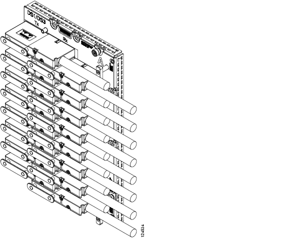
Figure 21-1 shows a UBIC-H with cables installed in all connectors.
Figure 21-1 Fully Cabled UBIC-H (A-Side)
Step 5
Note
Step 6
DLP-A442 Verify Pass-Through Circuits
Step 1
Step 2
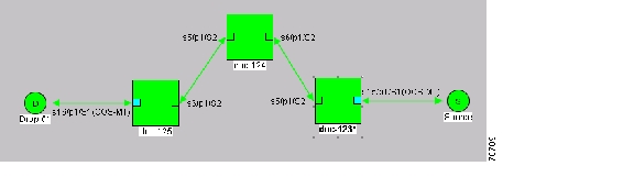
Step 3
Figure 21-2 Verifying Pass-Through STSs
Step 4
Step 5
Step 6
DLP-A469 Install GBIC or SFP Connectors
Purpose
This task installs GBICs (required for E-Series Ethernet, G-Series Ethernet, and FC_MR-4 cards) and Small Form-factor Pluggables (SFPs) (required for ML1000-2 and MXP cards). SFPs are hot-swappable input/output devices that plug into a line card port to link the port with the fiber-optic network. For a description of SFP connectors on transponder or muxponder cards, refer to the Cisco ONS 15454 DWDM Installation and Operations Guide.
Tools/Equipment
For the E1000-2-G use:
•
•
For the G1000-4 or G1K-4 card use:
•
•
•
•
For the ML1000-2 card use:
•
•
For the FC_MR-4 card use:
•
•
Prerequisite Procedures
DLP-A39 Install Ethernet Cards, page 17-48
Required/As Needed
As needed
Onsite/Remote
Onsite
Security Level
None
Note
Note
Note
Step 1
Step 2
Table 21-6 shows the available GBICs.
Note
Table 21-7 shows the available SFPs.
Step 3
•
•
•
Step 4
a.
Note
b.
c.
d.
Step 5
a.
b.
c.
d.
The click indicates that the GBIC is locked into the slot.
e.
Warning
Warning
Step 6
a.
b.
c.
Step 7
DLP-A470 Remove GBIC or SFP Connectors
Warning
Step 1
Step 2
a.
b.
Step 3
a.
b.
c.
Step 4
a.
b.
c.
d.
Step 5
DLP-A498 Switch Between TDM and DWDM Network Views
Step 1
Step 2
•
•
•
Note
Step 3
![]()
![]()
![]()
![]()
![]()
![]()
![]()
![]()
Posted: Wed Oct 17 09:50:27 PDT 2007
All contents are Copyright © 1992--2007 Cisco Systems, Inc. All rights reserved.
Important Notices and Privacy Statement.