|
|

Table Of Contents
DLP-A1 Unpack and Verify the Shelf Assembly
DLP-A2 Inspect the Shelf Assembly
DLP-A3 Reverse the Mounting Bracket to Fit a 19-inch (482.6 mm) Rack
DLP-A4 Install the External Brackets and Air Filter
DLP-A5 Mount the Shelf Assembly in a Rack (One Person)
DLP-A6 Mount the Shelf Assembly in a Rack (Two People)
DLP-A7 Mount Multiple Shelf Assemblies in a Rack
DLP-A10 Remove the Lower Backplane Cover
DLP-A11 Remove the Backplane Sheet Metal Cover
DLP-A12 Install a BNC or High-Density BNC EIA
DLP-A14 Install the AMP Champ EIA
DLP-A16 Connect the Office Ground to the ONS 15454
DLP-A17 Connect Office Power to the ONS 15454 Shelf
DLP-A18 Turn On and Verify Office Power
DLP-A19 Install Alarm Wires on the Backplane
DLP-A20 Install Timing Wires on the Backplane
DLP-A21 Install LAN Wires on the Backplane
DLP-A22 Install the TL1 Craft Interface
DLP-A23 Install DS-1 Cables Using Electrical Interface Adapters (Balun)
DLP-A24 Install DS-1 AMP Champ Cables on the AMP Champ EIA
DLP-A25 Install Coaxial Cable With BNC Connectors
DLP-A26 Install Coaxial Cable With High-Density BNC Connectors
DLP-A27 Install Coaxial Cable with SMB Connectors
DLP-A29 Route DS-1 and DS-3/EC-1 Twisted-Pair Cables
DLP-A30 Install Ferrites to Power Cabling
DLP-A31 Attach Ferrites to Wire-Wrap Pin Fields
DLP-A32 Inspect the Shelf Installation and Connections
DLP-A34 Create an Optimized 1+1 Protection Group
DLP-A35 Modify an Optimized 1+1 Protection Group
DLP-A36 Install the TCC2/TCC2P Cards
DLP-A37 Install the XCVT or XC10G Cards
DLP-A38 Install the Alarm Interface Controller or Alarm Interface Controller-International Card
DLP-A39 Install Ethernet Cards
DLP-A43 Install Fiber-Optic Cables for Path Protection Configurations
DLP-A44 Install Fiber-Optic Cables for BLSR Configurations
DLP-A45 Install the Fiber Boot
DLP-A52 Set Up a Windows PC for Craft Connection to an ONS 15454 Using Automatic Host Detection
DLP-A53 Set Up a Solaris Workstation for a Craft Connection to an ONS 15454
DLP-A56 Disable Proxy Service Using Internet Explorer (Windows)
DLP-A57 Disable Proxy Service Using Netscape (Windows and UNIX)
DLP-A61 Create Login Node Groups
DLP-A62 Add a Node to the Current Session or Login Group
DLP-A64 Set the IP Address, Default Router, and Network Mask Using the LCD
DLP-A67 Provision the IIOP Listener Port on the ONS 15454
DLP-A68 Provision the IIOP Listener Port on the CTC Computer
DLP-A69 Set Up External or Line Timing
DLP-A70 Set Up Internal Timing
DLP-A71 Create a 1:1 Protection Group
DLP-A72 Create a 1:N Protection Group
DLP-A73 Create a 1+1 Protection Group
DLP-A74 Create a New User on a Single Node
DLP-A75 Create a New User on Multiple Nodes
DLP-A88 Optical 1+1 Protection Test
DLP-A92 Four-Fiber BLSR Exercise Span Test
DLP-A93 Four-Fiber BLSR Span Switching Test
DLP-A94 Path Protection Switching Test
DLP-A95 Provision a DS-1 Circuit Source and Destination
DLP-A96 Provision a DS-1 or DS-3 Circuit Route
DLP-A97 Provision an OC-N Circuit Source and Destination
DLP-A99 Determine Available VLANs
DLPs A1 to A99
Note
The terms "Unidirectional Path Switched Ring" and "UPSR" may appear in Cisco literature. These terms do not refer to using Cisco ONS 15xxx products in a unidirectional path switched ring configuration. Rather, these terms, as well as "Path Protected Mesh Network" and "PPMN," refer generally to Cisco's path protection feature, which may be used in any topological network configuration. Cisco does not recommend using its path protection feature in any particular topological network configuration.
DLP-A1 Unpack and Verify the Shelf Assembly
Purpose
This task removes the shelf assembly from the package.
Tools/Equipment
None
Prerequisite Procedures
None
Required/As Needed
Required
Onsite/Remote
Onsite
Security Level
None
Step 1
Step 2
Step 3
Step 4
Note
Step 5
DLP-A2 Inspect the Shelf Assembly
Step 1
Step 2
•
•
Step 3
Step 4
Step 5
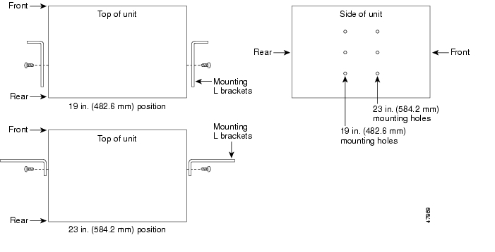
DLP-A3 Reverse the Mounting Bracket to Fit a 19-inch (482.6 mm) Rack
Caution
Caution
Step 1
Step 2
Text imprinted on the mounting bracket will now also be upside down.
Step 3
The narrow side of the mounting bracket should be towards the front of the shelf assembly. Text imprinted on the mounting bracket should be visible and upside down.
Step 4
Step 5
Step 6
Figure 17-1 Reversing the Mounting Brackets (23-inch [584.2-mm] Position to 19-inch [482.6-mm] Position)
Step 7
DLP-A4 Install the External Brackets and Air Filter
Purpose
This task installs the external brackets and air filter on the bottom of the shelf rather than below the fan-tray assembly. Installing the external brackets and air filter on the bottom of the shelf enables access to the air filter without removing the fan-tray assembly.
Tools/Equipment
#2 Phillips screwdriver
Medium slot-head screwdriver
Small slot-head screwdriver
Prerequisite Procedures
A3 Reverse the Mounting Bracket to Fit a 19-inch (482.6 mm) Rack, if applicable
Required/As Needed
As needed
Onsite/Remote
Onsite
Security Level
None
Note
Step 1
Note
Step 2
Step 3
Each bracket has a filter stopper and a flange on one end. Make sure to attach the brackets with the stoppers and flanges facing the rear of the shelf assembly (the top, if the ONS 15454 is facedown during installation).
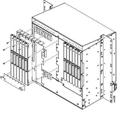
Figure 17-2 illustrates bottom bracket installation. If you do not use the brackets, in the future you must remove the fan-tray assembly before removing the air filter. The brackets enable you to clean and replace the air filter without removing the fan-tray assembly.
Figure 17-2 Installing the External Brackets
Step 4
Step 5
DLP-A5 Mount the Shelf Assembly in a Rack (One Person)
Purpose
This task allows one person to mount the shelf assembly in a rack.
Tools/Equipment
Pinned hex tool
Two set screws (48-1003-XX)
Eight pan-head Phillips mounting screws (48-1004-XX, 48-1007-XX)
#2 Phillips screwdriver
Prerequisite Procedures
A3 Reverse the Mounting Bracket to Fit a 19-inch (482.6 mm) Rack, if applicable
A4 Install the External Brackets and Air Filter, if applicable
Required/As Needed
As needed
Onsite/Remote
Onsite
Security Level
None
Step 1
•
•
Step 2
Step 3
Step 4
Step 5
Step 6
Step 7
Note
Step 8
Step 9
DLP-A6 Mount the Shelf Assembly in a Rack (Two People)
Purpose
This task allows two people to mount the shelf assembly in a rack.
Tools/Equipment
Pinned hex tool
Two set screws (48-1003-XX)
Eight pan-head Phillips mounting screws (48-1004-XX, 48-1007-XX)
#2 Phillips screwdriver
Prerequisite Procedures
A3 Reverse the Mounting Bracket to Fit a 19-inch (482.6 mm) Rack, if applicable
A4 Install the External Brackets and Air Filter, if applicable
Required/As Needed
Required
Onsite/Remote
Onsite
Security Level
None
Step 1
•
•
Step 2
Step 3
Step 4
Step 5
Step 6
Step 7
Note
Step 8
Step 9
DLP-A7 Mount Multiple Shelf Assemblies in a Rack
Purpose
This task allows multiple shelves to be assembled in a rack.
Tools/Equipment
#2 Phillips screwdriver
Medium slot-head screwdriver
Small slot-head screwdriver
Prerequisite Procedures
A3 Reverse the Mounting Bracket to Fit a 19-inch (482.6 mm) Rack, if applicable
A4 Install the External Brackets and Air Filter, if applicable
Required/As Needed
As needed
Onsite/Remote
Onsite
Security Level
None
Note
Step 1
•
•
Step 2
Step 3
Step 4
DLP-A8 Open the Front Door
Note
Step 1
The ONS 15454 comes with a pinned hex key for locking and unlocking the front door. Turn the key counterclockwise to unlock the door and clockwise to lock it.
Step 2
Step 3
Figure 17-3 Cisco ONS 15454 Front Door
Step 4
DLP-A9 Remove the Front Door
Purpose
This task removes the front cabinet compartment door.
Tools/Equipment
Open-end wrench
Prerequisite Procedures
Required/As Needed
As needed
Onsite/Remote
Onsite
Security Level
None
Step 1
a.
b.
Step 2
Figure 17-4 Removing the ONS 15454 Front Door
Step 3
DLP-A10 Remove the Lower Backplane Cover
Step 1
Step 2
Step 3
Step 4
DLP-A11 Remove the Backplane Sheet Metal Cover
Step 1
Step 2
Step 3
Step 4
Step 5
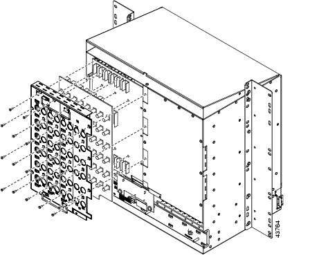
DLP-A12 Install a BNC or High-Density BNC EIA
Step 1
Step 2
Step 3
Step 4
Figure 17-5 shows a BNC EIA installation.
Figure 17-5 Installing the BNC EIA
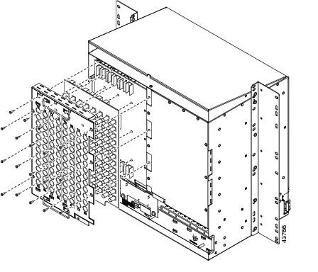
Figure 17-6 shows high-density BNC EIA installation.
Figure 17-6 Installing the High-Density BNC EIA
Step 5
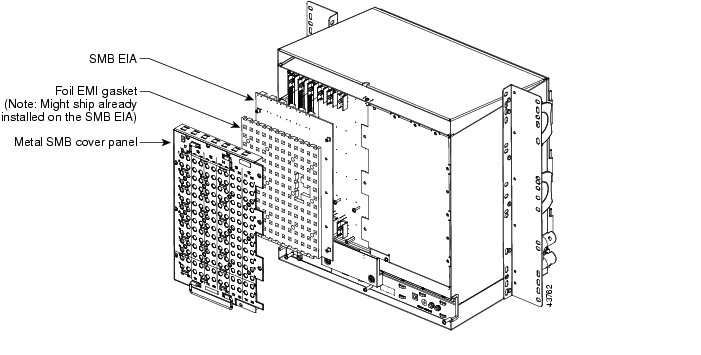
DLP-A13 Install an SMB EIA
Step 1
Step 2
Caution
Step 3
Step 4
Step 5
If you are using SMB EIAs to make DS-1 connections, you need the DS-1 electrical interface adapter, commonly referred to as a balun (P/N 15454-WW-14=).
Figure 17-7 shows an SMB EIA installation.
Figure 17-7 Installing the SMB EIA (Use a Balun for DS-1 Connections)
Step 6
DLP-A14 Install the AMP Champ EIA
Step 1
Step 2
Step 3
Step 4
Figure 17-8 shows an AMP Champ EIA installation.
Figure 17-8 Installing the AMP Champ EIA
Step 5
DLP-A16 Connect the Office Ground to the ONS 15454
Step 1
Step 2
Note
Figure 17-9 Ground Location on the Backplane
Step 3
Step 4
DLP-A17 Connect Office Power to the ONS 15454 Shelf
Warning
Note
Note
If you are using the TCC2/TCC2P cards, the system clock is kept running for up to three hours. In this case, no action is required.
Note
Step 1
Step 2
Step 3
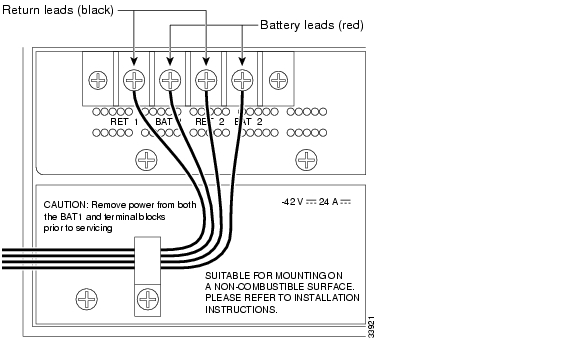
Warning
Figure 17-10 Cisco ONS 15454 Power Terminals
Step 4
Note
Caution
Caution
Step 5
Step 6
Note
Step 7
Warning
Step 8
Step 9
Step 10
Step 11
DLP-A18 Turn On and Verify Office Power
Purpose
This task measures the power to verify correct power and returns.
Tools/Equipment
Voltmeter
Prerequisite Procedures
A16 Connect the Office Ground to the ONS 15454
Required/As Needed
Required
Onsite/Remote
Onsite
Security Level
None
Step 1
a.
Note
b.
Step 2
•
•
Step 3
a.
Note
b.
Step 4
DLP-A19 Install Alarm Wires on the Backplane
Step 1
Figure 17-11 shows backplane alarm pin assignments for the AIC-I in ONS 15454 Release 3.4 or later.
Note
Figure 17-11 Cisco ONS 15454 Backplane Pinouts (Release 3.4 or Later)
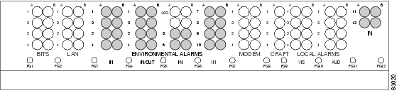
Figure 17-12 calls out the environmental alarm pins on the backplane for Release 3.4 or later.
Figure 17-12 Highlighted Environmental Alarms
Figure 17-13 shows alarm pin assignments for the AIC in a shelf for Release 3.3 and earlier.
Figure 17-13 Cisco ONS 15454 Backplane Pinouts (Release 3.3 or Earlier)
Note
Step 2
DLP-A20 Install Timing Wires on the Backplane
Step 1
Ground the shield of the BITS input cable at the BITS end. For BITS output, wrap the ground shield of the BITS cable to the frame ground pin (FG1) located beneath the column of BITS pins. Table 17-1 lists the pin assignments for the BITS timing pin fields.
Note
Step 2
DLP-A21 Install LAN Wires on the Backplane
Note
Step 1
Caution
A frame ground pin is located beneath each pin field (FG2 for the LAN pin field). Wrap the ground shield of the LAN interface cable to the frame ground pin. Table 17-2 shows the LAN pin assignments.
Note
Step 2
DLP-A22 Install the TL1 Craft Interface
Note
Step 1
Step 2
Wrap the ground wire of your computer cable to pin A3 on the craft pin field. Table 17-3 shows the pin assignments for the CRAFT pin field.
Note
Table 17-3 Craft Interface Pin Assignments
Craft
A1
Receive
A2
Transmit
A3
Ground
A4
DTR
Step 3
DLP-A23 Install DS-1 Cables Using Electrical Interface Adapters (Balun)
Note
Step 1
Step 2
Step 3
a.
b.
c.
Note
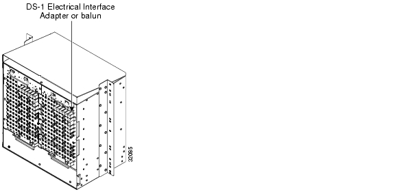
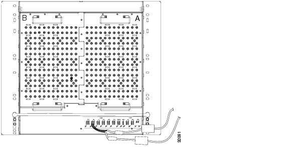
Figure 17-14 shows a ONS 15454 backplane with an SMB EIA. DS-1 electrical interface adapters are attached on both sides of the shelf assembly to create DS-1 twisted-pair termination points.
Figure 17-14 Backplane with an SMB EIA for DS-1 Cables
Step 4
DLP-A24 Install DS-1 AMP Champ Cables on the AMP Champ EIA
Step 1
Step 2
Step 3
The female connector has grooves on the outside edge for snapping the clips into place.
Table 17-4 shows the pin assignments for the AMP Champ connectors on the ONS 15454 AMP Champ EIA.
Note
Table 17-4 Pin Assignments for AMP Champ Connectors
Tx Tip 1
white/blue1
33
Tx Ring 1
blue/whiteRx Tip 1
yellow/orange17
49
Rx Ring 1
orange/yellowTx Tip 2 white/orange
2
34
Tx Ring 2
orange/whiteRx Tip 2
yellow/green18
50
Rx Ring 2
green/yellowTx Tip 3
white/green3
35
Tx Ring 3
green/whiteRx Tip 3
yellow/brown19
51
Rx Ring 3
brown/yellowTx Tip 4
white/brown4
36
Tx Ring 4
brown/whiteRx Tip 4
yellow/slate20
52
Rx Ring 4
slate/yellowTx Tip 5
white/slate5
37
Tx Ring 5
slate/whiteRx Tip 5
violet/blue21
53
Rx Ring 5
blue/violetTx Tip 6
red/blue6
38
Tx Ring 6
blue/redRx Tip 6
violet/orange22
54
Rx Ring 6
orange/violetTx Tip 7
red/orange7
39
Tx Ring 7
orange/redRx Tip 7
violet/green23
55
Rx Ring 7
green/violetTx Tip 8
red/green8
40
Tx Ring 8
green/redRx Tip 8
violet/brown24
56
Rx Ring 8
brown/violetTx Tip 9
red/brown9
41
Tx Ring 9
brown/redRx Tip 9
violet/slate25
57
Rx Ring 9
slate/violetTx Tip 10
red/slate10
42
Tx Ring 10
slate/redRx Tip 101
white/blue26
58
Rx Ring 10
blue/whiteTx Tip 11
black/blue11
43
Tx Ring 11
blue/blackRx Tip 11
white/orange27
59
Rx Ring 11
orange/whiteTx Tip 12
black/orange12
44
Tx Ring 12
orange/blackRx Tip 12
white/green28
60
Rx Ring 12
green/whiteTx Tip 13
black/green13
45
Tx Ring 13
green/blackRx Tip 13
white/brown29
61
Rx Ring 13
brown/whiteTx Tip 14
black/brown14
46
Tx Ring 14
brown/blackRx Tip 14
white/slate30
62
Rx Ring 14
slate/whiteTx Spare0+
Not applicable15
47
Tx Spare0-
Not applicableRx Spare0+
Not applicable31
63
Rx Spare0-
Not applicableTx Spare1+
Not applicable16
48
Tx Spare1-
Not applicableRx Spare1+
Not applicable32
64
Rx Spare1-
Not applicable
1 Pins 26, 27, 28, 29, 30, 58, 59, 60, 61, and 62 correspond to the white/orange binder group. A binder group is a set of 25 pairs of wires coded with an industry-standard color scheme.
Table 17-5 shows the pin assignments for the AMP Champ connectors on the ONS 15454 AMP Champ EIA for a shielded DS-1 cable.
Step 4
DLP-A25 Install Coaxial Cable With BNC Connectors
Purpose
This task installs the coaxial cable with BNC connectors.
Tools/Equipment
None
Prerequisite Procedures
Required/As Needed
As needed
Onsite/Remote
Onsite
Security Level
None
Step 1
Figure 17-15 shows how to connect a coaxial cable to the BNC EIA using a right-angle BNC cable connector.
Figure 17-15 Using a Right-Angle Connector to Install Coaxial Cable with BNC Connectors
Step 2
Step 3
Step 4
Step 5
Step 6
Warning
Step 7
Step 8
DLP-A26 Install Coaxial Cable With High-Density BNC Connectors
Step 1
Step 2
Step 3
Step 4
Step 5
Step 6
The rubber-coated edges of the side cutouts prevent the cables from chafing.
Step 7
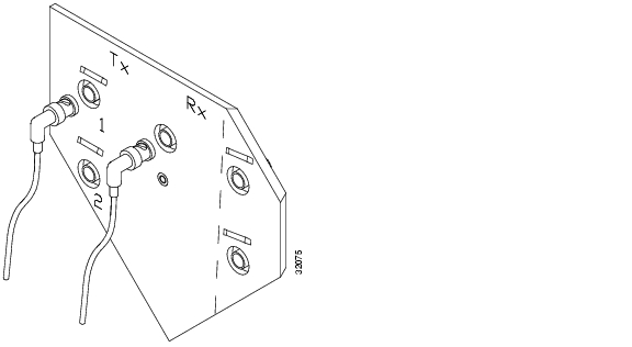
DLP-A27 Install Coaxial Cable with SMB Connectors
Purpose
This task installs the coaxial cable with SMB connectors.
Tools/Equipment
SMB cable connector
Prerequisite Procedures
Required/As Needed
As needed
Onsite/Remote
Onsite
Security Level
None
Step 1
Figure 17-16 Installing Coaxial Cable with SMB Connectors
Step 2
Step 3
Step 4
Warning
Step 5
Step 6
DLP-A28 Route Coaxial Cables
Purpose
This task routes the coaxial cables.
Tools/Equipment
RG179, RG59 (735A) #26 AWG cable, or RG59 (734A) #20 AWG cable
Prerequisite Procedures
One or more of the following tasks, as needed:
•
•
Required/As Needed
As needed
Onsite/Remote
Onsite
Security Level
None
Step 1
Step 2
Step 3
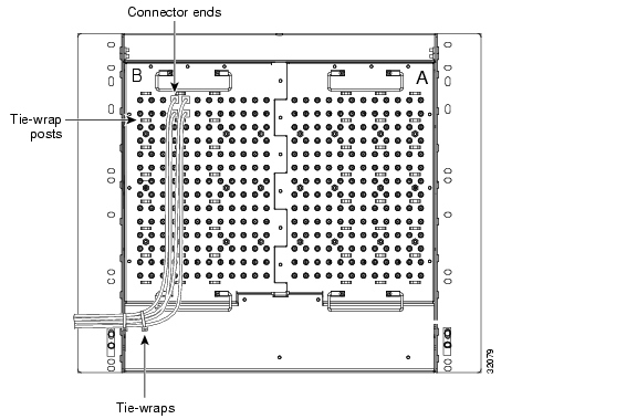
When using the RG179 cable, the maximum distance available (122 feet, 37.2 m) is less than the maximum distance available with standard RG59 (735A) cable (306 feet, 93.3 m). The maximum distance when using the RG59 (734A) cable is 450 feet (137.2 m). The shorter maximum distance available with the RG179 is due to a higher attenuation rate for the thinner cable. Attenuation rates are calculated using a DS-3 signal:
•
•
Use a figure of 5.0 for total cable loss when making calculations. Figure 17-17 shows an example of proper coaxial cable routing.
Figure 17-17 Routing Coaxial Cable (SMB EIA Backplane)
Step 4
DLP-A29 Route DS-1 and DS-3/EC-1 Twisted-Pair Cables
Purpose
This task routes the DS-1 and DS-3/EC-1 twisted-pair cables.
Tools/Equipment
None
Prerequisite Procedures
A23 Install DS-1 Cables Using Electrical Interface Adapters (Balun)
Required/As Needed
As needed
Onsite/Remote
Onsite
Security Level
None
Step 1
•
•
Step 2
Caution
Note
Step 3
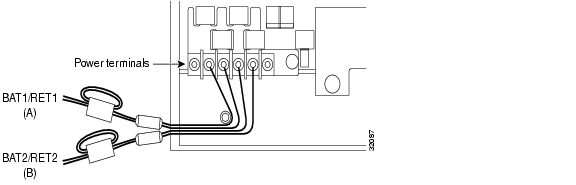
DLP-A30 Install Ferrites to Power Cabling
Step 1
Step 2
Figure 17-18 Attaching Block and Oval Ferrites to Power Cabling
Step 3
DLP-A31 Attach Ferrites to Wire-Wrap Pin Fields
Purpose
This task attaches ferrites to wire-wrap pin fields. Use an oval ferrite (TDK ZCAT1730-0730) and block ferrite (Fair Rite 0443164151) for each pair of cables. Figure 17-19 shows the suggested method for attaching ferrites to wire-wrap pin fields.
Tools/Equipment
Oval and block ferrites
Prerequisite Procedures
NTP-A8 Attach Wires to Alarm, Timing, LAN, and Craft Pin Connections, page 1-15
Required/As Needed
As needed
Onsite/Remote
Onsite
Security Level
None
Step 1
Step 2
Figure 17-19 Attaching Ferrites to Wire-Wrap Pin Fields
Step 3
DLP-A32 Inspect the Shelf Installation and Connections
Purpose
Use this task to inspect the shelf installation and connections and to verify that everything is installed and connected properly.
Tools/Equipment
None
Prerequisite Procedures
Complete Table 1-5 on page 1-30
Required/As Needed
Required
Onsite/Remote
Onsite
Security Level
None
Step 1
Step 2
Step 3
DLP-A33 Measure Voltage
Purpose
This task measures the power in order to verify correct power and returns.
Tools/Equipment
Voltmeter
Prerequisite Procedures
Complete Table 1-5 on page 1-30.
Required/As Needed
Required
Onsite/Remote
Onsite
Security Level
None
Step 1
a.
b.
Step 2
a.
•
•
•
b.
Step 3
DLP-A34 Create an Optimized 1+1 Protection Group
Step 1
Step 2
a.
b.
c.
Step 3
Step 4
Step 5
•
•
•
After you choose the protect card, a list of cards available for protection appear in the Available Ports list, as shown in Figure 17-34. If no cards are available, no cards appear. If this occurs, you cannot complete this task until you install the physical cards or preprovision the ONS 15454 slots using the "DLP-A330 Preprovision a Slot" task on page 20-20.
Step 6
Step 7
•
•
•
•
•
Step 8
DLP-A35 Modify an Optimized 1+1 Protection Group
Purpose
This task modifies an optimized 1+1 protection group for OC3 IR 4/STM1 SH 1310 and OC3 IR/STM1 SH 1310-8 cards.
Tools/Equipment
None
Prerequisite Procedures
A34 Create an Optimized 1+1 Protection Group
Required/As Needed
As needed
Onsite/Remote
Onsite or remote
Security Level
Provisioning or higher
Step 1
Step 2
Step 3
•
•
•
•
•
Step 4
Step 5
DLP-A36 Install the TCC2/TCC2P Cards
Note
Step 1
Step 2
Step 3
Note
If you insert a card into a slot provisioned for a different card, all LEDs turn off.
Step 4
a.
•
•
•
•
•
•
•
•
Note
Note
Note
Note
b.
•
•
•
•
•
•
•
•
•
•
Note
Note
Note
Note
Step 5
Step 6
Step 7
Refer to the release-specific software upgrade document to replace the software. To exchange the TCC2/TCC2P card, see the Cisco ONS 15454 Troubleshooting Guide.
Step 8
Tip
Note
Note
Step 9
Step 10
DLP-A37 Install the XCVT or XC10G Cards
Note
Note
Step 1
Step 2
Step 3
Note
Step 4
•
•
•
•
•
Note
Note
Note
Step 5
Step 6
Step 7
Note
Step 8
•
•
•
•
•
Note
Note
Note
Step 9
Step 10
DLP-A38 Install the Alarm Interface Controller or Alarm Interface Controller-International Card
Purpose
This task installs the Alarm Interface Controller (AIC) or Alarm Interface Controller-International (AIC-I) card. The AIC or AIC-I card provides connections for external alarms and controls (environmental alarms).
Tools/Equipment
AIC or AIC-I card
Prerequisite Procedures
A36 Install the TCC2/TCC2P Cards
Required/As Needed
As needed
Onsite/Remote
Onsite
Security Level
None
Note
Step 1
Step 2
Step 3
Note
Step 4
•
•
•
Step 5
•
•
•
Note
Note
Note
Note
Step 6
DLP-A39 Install Ethernet Cards
Step 1
Step 2
Step 3
Note
Step 4
For E-Series, G-Series and ML-Series cards:
•
•
•
•
For CE-100T-8 card:
•
•
•
•
Note
Note
Step 5
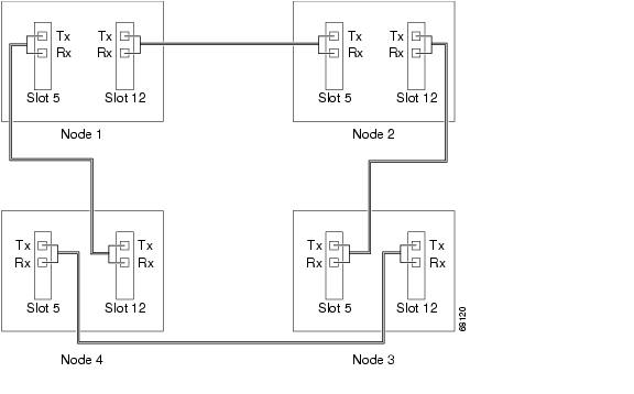
DLP-A43 Install Fiber-Optic Cables for Path Protection Configurations
Purpose
This task connects the fiber-optic cables to the east and west path protection ports at each node. See "Turn Up Network" to provision and test path protection configurations.
Tools/Equipment
Fiber-optic cables
Prerequisite Procedures
Required/As Needed
As needed
Onsite/Remote
Onsite
Security Level
None
Note
Caution
Step 1
Step 2
Step 3
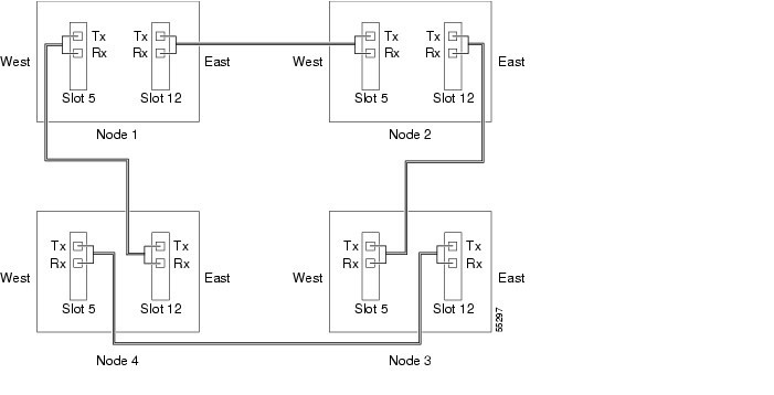
Figure 17-20 shows fiber connections for a four-node path protection with trunk (span) cards in Slot 5 (west) and Slot 12 (east).
Figure 17-20 Connecting Fiber to a Four-Node Path Protection
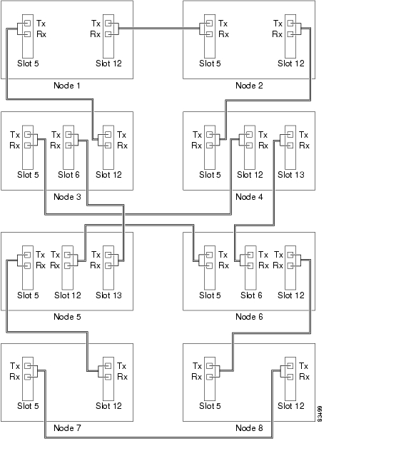
Figure 17-21 shows a traditional path protection dual-ring interconnect (DRI) example.
Figure 17-21 Connecting Fiber to an Eight-Node Traditional Path Protection Dual-Ring Interconnect
Figure 17-22 shows an integrated dual-ring interconnect (DRI) example.
Figure 17-22 Connecting Fiber to a Six-Node Integrated Path Protection Dual-Ring Interconnect
Step 4
DLP-A44 Install Fiber-Optic Cables for BLSR Configurations
Purpose
This task installs the fiber-optics to the east and west bidirectional line switched ring (BLSR) ports at each node. See "Turn Up Network" to provision and test BLSR configurations.
Tools/Equipment
Fiber-optic cables
Prerequisite Procedures
Required/As Needed
As needed
Onsite/Remote
Onsite
Security Level
None
Note
Caution
Step 1
Step 2
Note
Step 3
Figure 17-23 shows fiber connections for a two-fiber BLSR with trunk (span) cards in Slot 5 (west) and Slot 12 (east).
Figure 17-23 Connecting Fiber to a Four-Node, Two-Fiber BLSR
Figure 17-24 shows fiber connections for a four-fiber BLSR. Slot 5 (west) and Slot 12 (east) carry the working traffic. Slot 6 (west) and Slot 13 (east) carry the protect traffic.
Figure 17-24 Connecting Fiber to a Four-Node, Four-Fiber BLSR
Step 4
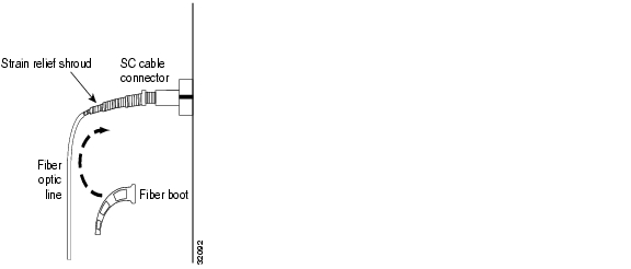
DLP-A45 Install the Fiber Boot
Note
Note
Note
Step 1
Step 2
Figure 17-25 Attaching a Fiber Boot
Step 3
Step 4
Step 5
DLP-A50 Set Up a Windows PC for Craft Connection to an ONS 15454 on the Same Subnet Using Static IP Addresses
Step 1
a.
b.
c.
Step 2
•
•
•
•
Step 3
a.
b.
c.
d.
e.
f.
g.
h.
i.
j.
k.
l.
m.
n.
Step 4
a.
b.
c.
d.
e.
f.
g.
h.
i.
j.
k.
l.
m.
n.
Step 5
a.
b.
c.
d.
e.
f.
g.
h.
i.
j.
Step 6
a.
Note
b.
c.
d.
e.
f.
g.
h.
i.
Step 7
DLP-A51 Set Up a Windows PC for Craft Connection to an ONS 15454 Using Dynamic Host Configuration Protocol
Note
Note
Step 1
a.
b.
c.
Step 2
•
•
•
•
Step 3
a.
b.
c.
d.
e.
f.
g.
h.
i.
Step 4
a.
b.
c.
d.
e.
f.
g.
h.
Step 5
a.
b.
c.
d.
e.
f.
g.
Step 6
a.
Note
b.
c.
d.
e.
f.
g.
h.
Step 7
DLP-A52 Set Up a Windows PC for Craft Connection to an ONS 15454 Using Automatic Host Detection
Step 1
a.
Note
b.
c.
Step 2
•
•
•
•
Step 3
a.
b.
c.
d.
e.
f.
g.
h.
i.
j.
k.
l.
m.
n.
Step 4
a.
b.
c.
d.
e.
f.
g.
h.
i.
j.
k.
l.
m.
n.
Step 5
a.
b.
c.
d.
e.
f.
g.
h.
i.
j.
Step 6
a.
Note
b.
c.
d.
e.
f.
g.
h.
i.
Step 7
DLP-A53 Set Up a Solaris Workstation for a Craft Connection to an ONS 15454
Step 1
Step 2
# ifconfig deviceFor example:
# ifconfig hme1If the interface is plumbed, a message similar to the following appears:
hme1:flags=1000842<BROADCAST,RUNNING,MULTICAST,IPv4>mtu 1500 index 2 inet 0.0.0.0 netmask
0
If a message similar to this one appears, go to Step 4.
If the interface is not plumbed, a message similar to the following appears:
ifconfig: status: SIOCGLIFFLAGS: hme1: no such interface.If a message similar to this one appears, go to Step 3.
Step 3
# ifconfig device plumbFor example:
# ifconfig hme1 plumbStep 4
# ifconfig interface ip-address netmask netmask upFor example:
# ifconfig hme0 192.1.0.3 netmask 255.255.255.0 up
Note
Step 5
Step 6
a.
b.
c.
ping ONS-15454-IP-addressFor example, to connect to an ONS 15454 with a default IP address of 192.1.0.2, type:
ping 192.1.0.2If your workstation is connected to the ONS 15454, the following message appears:
IP-address is alive
Note
d.
# ndd -set /dev/device instance 0# ndd -get /dev/device link_statusFor example:
# ndd -set /dev/hme instance 0# ndd -get /dev/hme link_statusA result of "1" means the link is up. A result of "0" means the link is down.
Note
#man ndd.Step 7
DLP-A56 Disable Proxy Service Using Internet Explorer (Windows)
Step 1
Note
Step 2
Step 3
Step 4
•
•
Note
Step 5
DLP-A57 Disable Proxy Service Using Netscape (Windows and UNIX)
Step 1
Step 2
Step 3
Step 4
•
•
Note
Step 5
DLP-A60 Log into CTC
Purpose
This task logs into CTC.
Tools/Equipment
None
Prerequisite Procedures
One of the following procedures:
•
•
Required/As Needed
Required
Onsite/Remote
Onsite or remote
Security Level
Retrieve or higher
Note
Step 1
•
•
–
# netscape -install–
# netscape -ncols 32
Note
Step 2
Note
If a Java Plug-in Security Warning dialog box appears, complete the "DLP-A418 Install Public-Key Security Certificate" task on page 21-6 to install the public-key security certificate required by Software Release 4.1 and later.
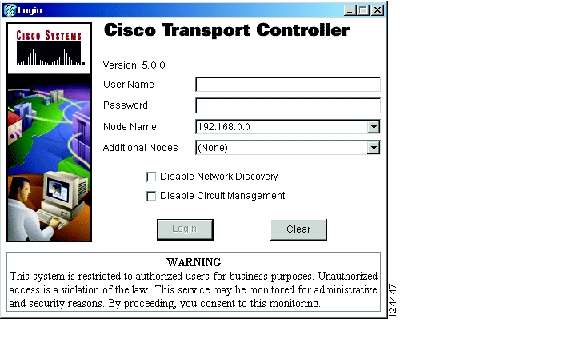
After you complete the security certificate dialog box (or if the certificate is already installed), a Java Console window displays the CTC file download status. The web browser displays information about your Java and system environments. If this is the first login, CTC caching messages appear while CTC files are downloaded to your computer. The first time you connect to an ONS 15454, this process can take several minutes. After the download, the CTC Login dialog box appears ( Figure 17-26).
Figure 17-26 Logging into CTC
Step 3
Note
Step 4
•
•
•
•
Step 5
If the login is successful, the CTC window appears. From here, you can navigate to other CTC views to provision and manage the ONS 15454. If you need to turn up the shelf for the first time, see Chapter 4, "Turn Up Node." If login problems occur, refer to the Cisco ONS 15454 Troubleshooting Guide.
Step 6
DLP-A61 Create Login Node Groups
Step 1
Step 2
Step 3
Step 4
Note
Step 5
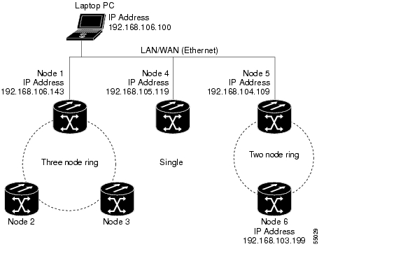
The next time you log into an ONS 15454, the login node group will be available in the Additional Nodes list of the Login dialog box. For example, in Figure 17-27, a login node group is created that contains the IP addresses for Nodes 1, 4, and 5. During login, if you choose this group from the Additional Nodes list and Disable Network Discovery is not selected, all nodes in the figure appear. If the login group and Disable Network Discovery are both selected, Nodes 1, 4, and 5 appear. You can create as many login groups as you need. The groups are stored in the CTC preferences file and are not visible to other users.
Figure 17-27 Login Node Group
Step 6
DLP-A62 Add a Node to the Current Session or Login Group
Step 1
Step 2
Note
Step 3
Note
Step 4
After a few seconds, the new node appears on the network view map.
Step 5
DLP-A64 Set the IP Address, Default Router, and Network Mask Using the LCD
Note
Note
Step 1
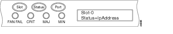
Step 2
•
•
•
Figure 17-28 Selecting the IP Address Option
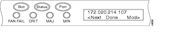
Step 3
Figure 17-29 Changing the IP Address
Step 4
Tip
Step 5
Step 6
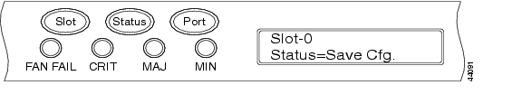
Step 7
Figure 17-30 Selecting the Save Configuration Option
Step 8
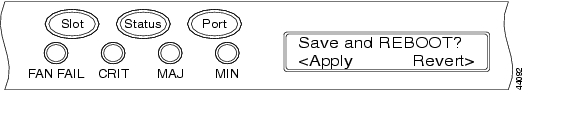
A Save and REBOOT message appears ( Figure 17-31).
Figure 17-31 Saving and Rebooting the TCC2/TCC2P
Step 9
Saving the new configuration causes the TCC2/TCC2P cards to reboot. During the reboot, a "Saving Changes - TCC Reset" message displays on the LCD. The LCD returns to the normal alternating display after the TCC2/TCC2P reboot is complete.
Note
Step 10
DLP-A65 Create a Static Route
Step 1
Step 2
Step 3
•
•
•
•
Step 4
Note
Step 5
DLP-A67 Provision the IIOP Listener Port on the ONS 15454
Note
Step 1
Step 2
•
•
•
Step 3
Step 4
Both ONS 15454 TCC2/TCC2P cards reboot, one at a time. The reboot takes approximately 15 minutes.
Step 5
DLP-A68 Provision the IIOP Listener Port on the CTC Computer
Purpose
This task selects the IIOP listener port on CTC.
Tools/Equipment
IIOP listener port number from LAN or firewall administrator.
Prerequisite Procedures
NTP-A24 Verify Card Installation, page 4-2
Required/As Needed
Required only if the computer running CTC resides behind a firewall.
Onsite/Remote
Onsite or remote
Security Level
Provisioning or higher
Step 1
Step 2
Step 3
•
•
•
Step 4
Step 5
Step 6
Step 7
Step 8
DLP-A69 Set Up External or Line Timing
Step 1
Step 2
•
Note
•
•
•
•
Step 3
Note
•
–
–
–
•
Step 4
Note
Step 5
•
•
Step 6
•
•
•
•
Step 7
•
•
Step 8
•
•
•
•
Step 9
Note
Step 10
DLP-A70 Set Up Internal Timing
Caution
Step 1
Step 2
•
•
•
•
•
Step 3
•
–
–
–
•
Step 4
Step 5
Step 6
Step 7
DLP-A71 Create a 1:1 Protection Group
Step 1
Step 2
Step 3
Step 4
•
•
•
After you choose the protect card, the card available for protection appear in the Available Cards list, as shown in Figure 17-32. If no cards are available, no cards appear. If this occurs, you can not complete this task until you install the physical cards or preprovision the ONS 15454 slots using the "DLP-A330 Preprovision a Slot" task on page 20-20.
Figure 17-32 Creating a 1:1 Protection Group
Step 5
Step 6
•
•
•
Step 7
Step 8
DLP-A72 Create a 1:N Protection Group
Step 1
Step 2
Step 3
Step 4
•
•
•
After you choose the protect card, a list of cards available for protection appear in the Available Cards list, as shown in Figure 17-33. If no cards are available, no cards appear. If this occurs, you can not complete this task until you install the physical cards or preprovision the ONS 15454 slots using the "DLP-A330 Preprovision a Slot" task on page 20-20.
Figure 17-33 Creating a 1:N Protection Group
Step 5
Step 6
•
•
•
Step 7
Step 8
DLP-A73 Create a 1+1 Protection Group
Step 1
Step 2
Step 3
Step 4
•
•
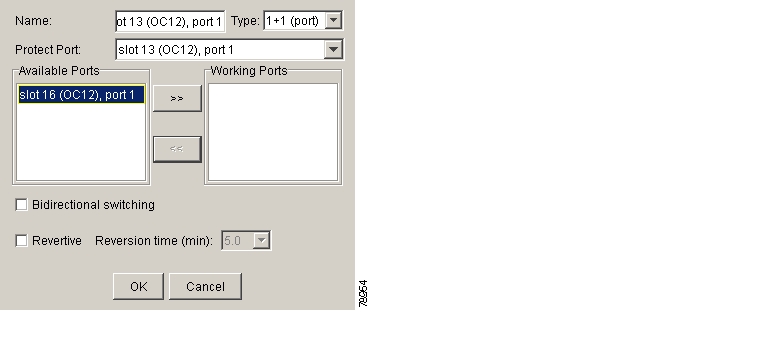
•
After you choose the protect port, a list of ports available for protection appear in the Available Ports list, as shown in Figure 17-34. If no cards are available, no ports appear. If this occurs, you can not complete this task until you install the physical cards or preprovision the ONS 15454 slots using the "DLP-A330 Preprovision a Slot" task on page 20-20.
Figure 17-34 Creating a 1+1 Protection Group
Step 5
Step 6
•
•
•
Step 7
Step 8
DLP-A74 Create a New User on a Single Node
Purpose
This task creates a new user for one ONS 15454.
Tools/Equipment
None
Prerequisite Procedures
Required/As Needed
As needed
Onsite/Remote
Onsite or remote
Security Level
Superuser
Step 1
Step 2
Step 3
•
•
•
•
Note
Step 4
Step 5
DLP-A75 Create a New User on Multiple Nodes
Purpose
This task adds a new user to multiple ONS 15454s.
Tools/Equipment
None
Prerequisite Procedures
Required/As Needed
As needed
Onsite/Remote
Onsite or remote
Security Level
Superuser
Note
Step 1
Step 2
Step 3
Step 4
•
•
•
•
Note
Step 5
Step 6
Step 7
Step 8
DLP-A83 Provision Orderwire
Purpose
This task provisions orderwire on the AIC or the AIC-I card.
Tools/Equipment
An AIC or AIC-I card must be installed in Slot 9.
OC-N cards must be installed.
Prerequisite Procedures
NTP-A24 Verify Card Installation, page 4-2
Required/As Needed
As needed
Onsite/Remote
Onsite or remote
Security Level
Provisioning or higher
Step 1
Step 2
Step 3
•
•
•
Caution
Step 4
Step 5
•
•
•
Step 6
Step 7
•
•
•
Step 8
Step 9
DLP-A88 Optical 1+1 Protection Test
Purpose
This task verifies that a 1+1 protection group will switch traffic properly.
Tools/Equipment
The test set specified by the acceptance test procedure.
Prerequisite Procedures
A60 Log into CTC; a test circuit created as part of the topology acceptance test.
Required/As Needed
Required
Onsite/Remote
Onsite
Security Level
Provisioning or higher
Step 1
Step 2
a.
b.
Step 3
Step 4
Step 5
Step 6
a.
b.
c.
d.
•
•
Step 7
Step 8
a.
b.
Step 9
a.
b.
c.
•
•
Step 10
Step 11
a.
b.
c.
•
•
Step 12
DLP-A89 Remap the K3 Byte
Caution
Step 1
Step 2
Step 3
Step 4
Step 5
Step 6
Note
Step 7
DLP-A91 BLSR Switch Test
Step 1
Step 2
Step 3
Step 4
a.
Note
b.
c.
d.
On the network view graphic, an F appears on the BLSR channel where you invoked the Force Ring switch. The BLSR span lines turn purple where the switch was invoked, and all span lines between other BLSR nodes turn green.
Step 5
a.
b.
c.
•
•
Note
d.
•
•
Step 6
Step 7
a.
b.
c.
•
•
•
Step 8
Step 9
a.
b.
Step 10
Step 11
a.
b.
c.
d.
On the network view graphic, the Force Ring switch is removed, the F indicating the switch is removed, and the span lines between BLSR nodes will be purple and green. The span lines might take a few moments to change color.
Step 12
Step 13
a.
a.
b.
Step 14
a.
b.
c.
d.
On the network view graphic, an F appears on the working BLSR channel where you invoked the Force Ring switch. The BLSR span lines are purple where the Force Ring switch was invoked, and all span lines between other BLSR nodes are green. The span lines might take a few moments to change color.
Step 15
a.
b.
c.
•
•
Note
d.
•
•
Step 16
Step 17
a.
b.
•
•
•
Step 18
Step 19
a.
b.
Step 20
Step 21
a.
b.
c.
d.
On the network view graphic, the Force Ring switch is removed, the F indicating the switch is removed, and the span lines between BLSR nodes will be purple and green. The span lines might take a few moments to change color.
Step 22
Step 23
a.
b.
c.
Step 24
Step 25
DLP-A92 Four-Fiber BLSR Exercise Span Test
Step 1
Step 2
Step 3
Step 4
a.
Note
b.
c.
On the network view graphic, an E appears on the BLSR channel where you invoked the exercise. The E will appear for 10 to 15 seconds, then disappear.
Step 5
a.
b.
•
•
•
Note
Step 6
a.
b.
Step 7
a.
b.
c.
d.
On the network view graphic, an E appears on the BLSR channel where you invoked the exercise. The E will appear for 10 to 15 seconds, then disappear.
Step 8
Step 9
a.
b.
•
•
•
Note
Step 10
a.
b.
Step 11
Step 12
DLP-A93 Four-Fiber BLSR Span Switching Test
Step 1
Step 2
Step 3
Note
Step 4
a.
Note
b.
c.
d.
On the network view graphic, an F appears on the BLSR channel where you invoked the protection switch. The BLSR span lines turn purple where the Force Span switch was invoked, and all span lines between other BLSR nodes turn green.
Step 5
a.
b.
c.
Step 6
a.
b.
Step 7
Step 8
a.
b.
c.
d.
On the network view graphic, the Force Span switch is removed, the F disappears, and the span lines between BLSR nodes will be purple and green. The span lines might take a few moments to change color.
Step 9
a.
b.
c.
d.
On the network view graphic, an F appears on the BLSR channel where you invoked the Force Span switch. The BLSR span lines are purple where the Force Span switch was invoked, and all span lines between other BLSR nodes are green. The span lines might take a few moments to change color.
Step 10
a.
b.
c.
Step 11
a.
b.
Step 12
Step 13
a.
b.
c.
d.
On the network view graphic, the Force Span switch is removed, the F indicating the switch is removed, and the span lines between BLSR nodes will be purple and green. The span lines might take a few moments to change color.
Step 14
Step 15
DLP-A94 Path Protection Switching Test
Note
Step 1
Step 2
The Circuits on Span dialog box shows the path protection circuits, including circuit names, locations, and a color code showing which circuits are active on the span.
Step 3
a.
b.
c.
d.
e.
In the Circuits on Span dialog box, the Switch State for all circuits is FORCE. Unprotected circuits will not switch.
Step 4
a.
b.
c.
d.
e.
In the Circuits on Span window, the Switch State for all path protection circuits is CLEAR.
Step 5
DLP-A95 Provision a DS-1 Circuit Source and Destination
Note
Step 1
Step 2
Note
Step 3
Step 4
Step 5
Step 6
Step 7
Step 8
Step 9
Step 10
Step 11
Step 12
DLP-A96 Provision a DS-1 or DS-3 Circuit Route
Step 1
Step 2
Step 3
Step 4
Note
Step 5
Step 6
•
•
•
Step 7
Step 8
DLP-A97 Provision an OC-N Circuit Source and Destination
Step 1
Step 2
Step 3
Note
Step 4
Step 5
Step 6
Step 7
Step 8
Step 9
Step 10
Step 11
DLP-A99 Determine Available VLANs
Purpose
This task verifies that the network has the capacity to support the additional new VLANs required for the creation E-Series circuits. It does not apply to E-Series cards in port-mapped mode.
Tools/Equipment
E-Series Ethernet cards (E100T-12/E100T-G, E1000-2/E1000-2-G) must be installed at each end of the Ethernet circuit.
Prerequisite Procedures
NTP-A127 Verify Network Turn Up, page 6-4
Required/As Needed
As needed
Onsite/Remote
Onsite or remote
Security Level
Provisioning or higher
Step 1
Step 2
Step 3
The Edit Circuit dialog box shows the number of VLANs used by circuits and the total number of VLANs available for use.
Step 4
Caution
Step 5
![]()
![]()
![]()
![]()
![]()
![]()
![]()
![]()
Posted: Wed Oct 17 10:03:05 PDT 2007
All contents are Copyright © 1992--2007 Cisco Systems, Inc. All rights reserved.
Important Notices and Privacy Statement.