|
|

Table Of Contents
Data Communications Channel (DCC) Operations
I/O Interfaces Cross-Connect Capabilities
Multiple Destinations for Unidirectional Circuits
BLSR Protection Channel Access Circuits
Synchronous Status Messaging (SSM)
Automatic Protection Switching
Dual-Ring Interconnect—Path Protection
Protection Switch Initiation Time
Protection Switch Completion Time
Linear Add/Drop Multiplexer Network
Two-Fiber Bidirectional Path Switched Ring
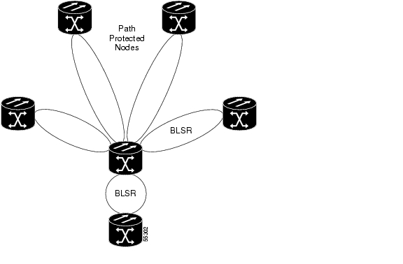
Path-Protected Meshed Networks
Inservice Topology Conversions
Unprotected Point-to-Point or Linear ADM to Path Protection
Point-to-Point or Linear ADM to Two-Fiber BLSR
Path Protection to Two-Fiber BLSR
Two-Fiber BLSR to Four-Fiber BLSR
Add or Remove a Node from a Topology
SONET Transport
Note
The terms "Unidirectional Path Switched Ring" and "UPSR" may appear in Cisco literature. These terms do not refer to using Cisco ONS 15xxx products in a unidirectional path switched ring configuration. Rather, these terms, as well as "Path Protected Mesh Network" and "PPMN," refer generally to Cisco's path protection feature, which may be used in any topological network configuration. Cisco does not recommend using its path protection feature in any particular topological network configuration.
This chapter contains specific information about Synchronous Optical Network (SONET) line rates, signal format, overhead functions, and payload mappings for the Cisco ONS 15454. For an introduction to SONET, see the SONET primer in Appendix B. For information about Telcordia's generic requirements for SONET, see GR-253-CORE.
The following topics are covered in this chapter:
•
•
Rates and Formats
Inside the ONS 15454, STS-N connections may be allowed that do not correspond to the standard signal definitions. For example, Ethernet card connections in the ONS 15454 may be made with the standard signals and also STS-6C and STS-24C line rates, because the STS-6C and STS-24C signals are carried within standard SONET links and never appear outside of the ONS 15454 system. Table 2-1 lists the SONET line rates supported by the ONS 15454.
STS Concatenation
In the ONS 15454, valid concatenated payloads exist from STS-1 to STS-192c and are carried in the optical OC-N signal or STS-N electrical signal. Valid STS-Nc payloads for the ONS 15454 are listed in Table 2-2.
When STS-1's are concatenated, the path overhead in the first STS-1 controls the payload. Path overhead in the remaining STS-1's is still carried, but it is not used.
Concatenated STS Time Slot Assignments
Table 2-3 shows the available time slot assignments for concatenated STSs when using CTC to provision circuits.
VT Structure
Signals with bit rates less than DS3 at 45 Mb/s can be carried in the ONS 15454 by mapping these lower rate signals into sections of an STS-1 frame. These sections are each called a Virtual Tributary (VT). Each STS-1 frame is divided into exactly seven virtual tributary groups (VTG).
A single STS-1 frame cannot be partially filled with VTGs and use its remaining payload for something else, like ATM cell transport. The STS-1 can either be sectioned off into exactly 7 VTGs or left whole. The 7 VTGs in an STS-1 frame consists of 108 bytes each.
The ONS 15454 system utilizes the Asynchronous VT1.5 structure, which is diagramed in Figure 2-1. Note that there are 27 bytes in the VT1.5. 24 bytes make up the payload of the DS1 signal. The remaining 3 bytes are used for path overhead.
Figure 2-1 VT1.5 Structure
Each STS-1 can support 28 VT1.5 mapped DS1 signals. Table 2-4 illustrates how the ONS 15454 numbers these VT1.5 mapped signals compared to the VT Group numbering scheme defined in Telcordia GR-253-CORE.
M13 Multiplexing
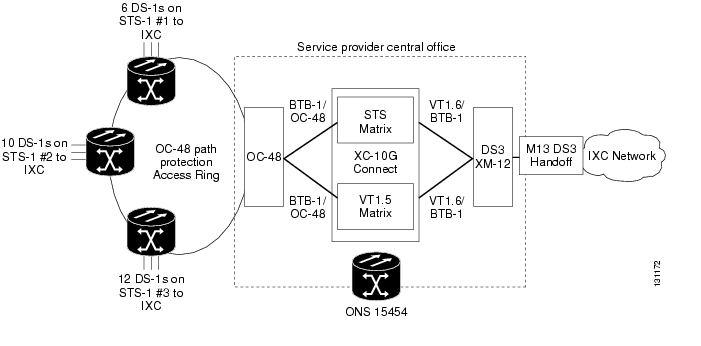
The ONS 15454 provides GR499-CORE compliant M13 multiplexing to groom D1s into channelized DS3 signals. This transmux function is provided by the DS3XM-6 and DS3XM-12 transmux cards. In Figure 2-2, the ONS 15454 is pictured collecting multiple DS1s from IXC customers around the OC-48 path protection access ring and, in the ONS 15454 node at the Service Provider's Central Office, transmitting them within a channalized DS3 signal to the IXC's network.
Figure 2-2 Ported Transmux Function
The DS3XM-6 and DS3XM-12 cards can terminate either C-bit or M13 formatted DS-3 signals and demultiplex them into DS1 signals for transport as VC11/VT1.5 payloads. Each DS3 signal is partitioned into M-frames mapped to 28 DS-1 signals in an M13 multiplex unit. The 28 DS-1 signals are then converted to VT1.5 payloads (1.728 Mb/s) for DS-1 transport.
Conversely, these transmux cards can take 28 T-1s and multiplex them into a channeled C-bit or M13 framed DS3. This is accomplished in two steps. In the first step, 4 DS1 signals are multiplexed to reach a 6.312 Mb/s transmission rate inside the M13 multiplex unit. The M13 unit then multiplexes 7 of the 6.312 Mb/s signals to generate the DS3 output.
With the introduction of the DS3XM-12 card in Release 5.0, the ONS 15454 can support up to 96 DS3 transmux ports in a single shelf.
Portless Transmux Function
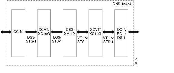
The portless transmux function enables the ONS 15454 to multiplex and demultiplex DS3 signals directly from optical interfaces without requiring an external DS3 card to groom DS1s from DS3 signals inside an STS-1 from an optical port. Only the DS3XM-12 card can provide this function, which is illustrated in Figure 2-3.
Figure 2-3 Portless Transmux Function
Only the DS3XM-12 card provides portless transmux interfaces that can change transported DS3s within optical interfaces into VT1.5s. Each DS3XM-12 card can provide either 6 or 12 portless transmux interfaces depending on the card's slot position and the type of cross-connect card as follows:
If the DS3XM12 card is in slots 1-4 or 14-17 and the cross-connect is an XC-VT then the backplane bandwidth size is an STS-12, which supports a maximum of 6 portless transmux ports.
If the DS3XM12 card is slots 5-6 or 12-13 and the cross-connect is an XC-VT, or slots 1-6 and 12-17 and cross-connect is an XC-10G the backplane size is an STS-48, which supports a maximum of 12 portless transmux ports.
Overhead Mapping
The individual SONET overhead byte designations are laid out in Table 2-5.
Table 2-6 provides a list of supported and unsupported SONET overhead bytes for the Cisco ONS 15454.
Data Communications Channel (DCC) Operations
SONET provides four data communications channels (DCCs) for network element operation, administration, maintenance, and provisioning: one on the SONET Section layer (D1 to D3 bytes) and three on the SONET Line layer (D4 to D12 bytes). The ONS 15454 uses the Section DCC (SDCC) for ONS 15454 management and provisioning. An SDCC and Line DCC (LDCC) each provide 192 Kb/s of bandwidth per channel. The aggregate bandwidth of the three LDCCs is 576 Kb/s. When multiple DCC channels exist between two neighboring nodes, the ONS 15454 balances traffic over the existing DCC channels using a load balancing algorithm. This algorithm chooses a DCC for packet transport by considering packet size and DCC utilization.
Note
The SDCC is defined in the first STS-1 of an STS-N frame. SDCC channels need to be terminated via a provisioning session at each ONS 15454 node in the ring before messages can flow between nodes. After the SDCC channels have been terminated, OAM&P will start up automatically within each ONS 15454 node. If there are two ONS 15454 nodes connected by multiple OC-N spans, the SDCC on each of these spans does not have to be terminated at each node to start the flow of OAM&P information. You only need to terminate the SDCCs on the ports of the OC-N cards that are going to serve as the OC-N trunk ports for the ring. SDCCs that are not terminated are available for DCC tunneling.
A SONET link that carries payload from an ONS 15454 node to a third-party's SONET node will also have an SDCC defined in the Section Overhead. However, OAM&P messages will not be recognized by the third-party's node, and the SDCC should not be enabled. Disabling the SDCC will not have any affect on the DS3, DS1, and other payload signals carried between nodes.
DCC Tunneling
Note
You can tunnel the SONET DCC from third party equipment across ONS 15454 networks using one of two tunneling methods, a traditional DCC tunnel or an IP-encapsulated tunnel.
Traditional DCC Tunnels
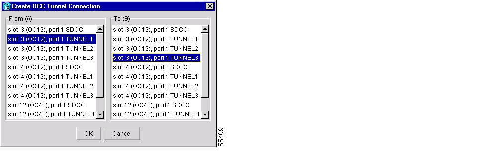
In traditional DCC tunnels, you can use the 3 LDCCs and the SDCC (when not used for ONS 15454 DCC terminations) for a maximum of 4 DCC tunnels. A traditional DCC tunnel endpoint is defined by slot, port, and DCC, where a DCC can be either the section DCC or one of the line DCCs (see Figure 2-4). You can link LDCCs to LDCCs and link SDCCs to SDCCs. You can also link a SDCC to a LDCC, and a LDCC to a SDCC. To create a DCC tunnel, you connect the tunnel endpoints from one ONS 15454 optical port to another. Software Release 4.0 and higher can support a maximum of 84 DCC tunnel connections for each ONS 15454. Table 2-7 shows the DCC tunnels that you can create using different OC-N cards.
Figure 2-4 Selecting DCC Tunnel End-Points
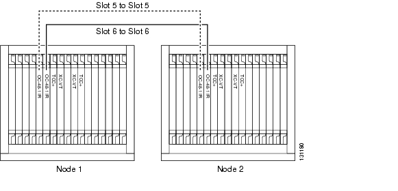
Figure 2-5 shows an example of a DCC tunnel. Third-party equipment is connected to OC-3 cards at Node 1/Slot 3/Port 1 and Node 3/Slot 3/Port 1. OC-48 trunk cards connect each ONS 15454 node. In the example, 3 tunnel connections are created, 1 at Node 1 (OC-3 to OC-48), 1 at Node 2 (OC-48 to OC-48), and 1 at Node 3 (OC-48 to OC-3).
Figure 2-5 DCC Tunnel Example
When you create DCC tunnels, keep the following guidelines in mind:
•
•
•
•
•
IP-Encapsulated Tunnels
An IP-encapsulated tunnel puts a SDCC in an IP packet at a source node and dynamically routes the packet to a destination node. To compare traditional DCC tunnels with IP-encapsulated tunnels, a traditional DCC tunnel is configured as one dedicated path across a network and does not provide a failure recovery mechanism if the path is down. An IP-encapsulated tunnel is a virtual path, which adds protection when traffic travels between different networks.
IP-encapsulated tunneling has the potential of flooding the DCC network with traffic resulting in a degradation of performance for CTC. The data originating from an IP tunnel can be throttled to a user-specified rate, which is a percentage of the total SDCC bandwidth.
Each ONS 15454 supports up to 10 IP-encapsulated tunnels. You can convert a traditional DCC tunnel to an IP-encapsulated tunnel or an IP-encapsulated tunnel to a traditional DCC tunnel. Only tunnels in the DISCOVERED state can be converted.
Caution
K1 and K2 Byte Switching
The K1 and K2 bytes in the Line Overhead are used for automatic protection switching (APS) commands and error conditions between pieces of SONET node equipment. These two bytes are only used in the first STS-1 of an STS-N signal. The meaning of the K1 and K2 bytes depends on the type of protection used. For example, bits 1-4 of the K1 byte have the following meaning shown in Table 2-8 when a 1+1 fiber protection scheme is used.
Remember that the SONET overhead is sent with the SONET frame every 125 microseconds between nodes. So if a SONET node detects a fault on the receive bit stream from a node, the receiving node can notify the transmitting node immediately by changing the state of the K1 and K2 bytes. The transmitting node does not have to compose a message and send it through the DCC channels. The node receiving the new K1/K2 state must begin processing the change within three frame receptions (3 times 125 microseconds or 375 microseconds). The ONS 15454 conforms to the GR-253-CORE standard for K1 and K2 state signaling, so other vendor equipment should be interoperable with ONS 15454 transmission payload and protection signaling.
K3 Byte Remapping
Warning
The Cisco ONS 15454 uses the undefined K1 byte within STS-2 to improve BLSR switching times. Cisco renamed the K1 byte within STS-2 the K3 byte. The improved switching time allows a Cisco to support the 50ms BLSR switch time in rings with up to 16 ONS 15454 nodes.
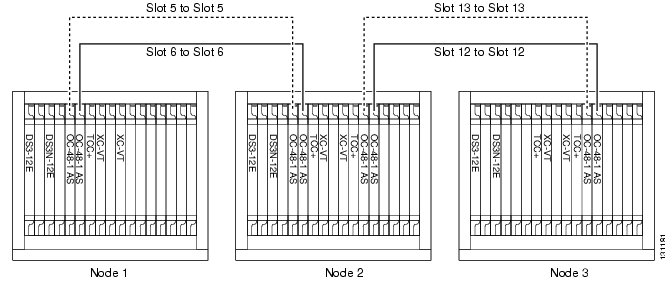
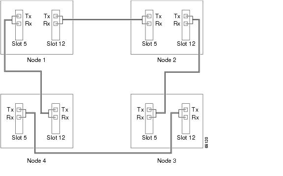
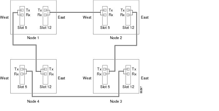
If a BLSR is routed through third-party equipment that cannot transparently transport the K3 byte, you can remap it to either the Z2, E2, or F1 bytes on the ONS 15454 OC-48 any slot (AS) cards. K3 byte remapping is not available on other OC-N cards. If you remap the K3 byte, you must remap it to the same byte on each BLSR trunk card that connects to the third-party equipment. All other BLSR trunk cards should remain mapped to the K3 byte.
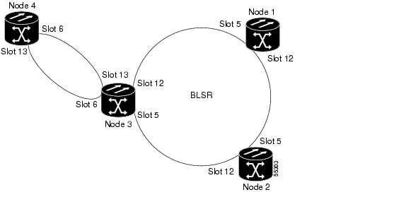
For example, in Figure 2-6, a BLSR span between Node 2 and Node 4 passes through third-party equipment. Because this equipment cannot transparently transport the K3 byte, the OC-48AS card at Node 2/Slot 12 and the OC-48AS card at Node 4/Slot 5 are provisioned to use an alternate byte. Other BLSR trunk cards are not changed.
Figure 2-6 BLSR Provisioned with Remapped K3 Byte
J1 and J2 Path Trace
The SONET J1 and J2 Path Trace is a repeated, fixed-length string comprised of 64 consecutive J1 bytes. J1 Path Trace can be used to carry a remote hostname, an interface name/number, an IP address, or anything that can be used to uniquely identify a circuit. J1 Path Trace is commonly used to troubleshoot circuit paths through networks. The Cisco ONS 15454 can monitor the J1 Path Trace strings on each STS and compare the received string with the transmitted string. A TIM-P alarm is raised if the string received at a circuit drop port does not match the string the port expects to receive. Two path trace modes are available:
•
•
Table 2-9 shows the ONS 15454 cards that support J1 Path Trace. DS-1 and DS-3 cards can transmit and receive the J1 field, while the EC-1, OC-3, OC-48AS, and OC-192 can only receive it. A new feature added in System Release 4.0 gives the ONS 15454 the ability to support J1 Path Trace monitoring while a BLSR switch is in effect. Cards not listed in the table do not support the J1 byte. The DS3XM-12 card supports J2 path trace for VT circuits.
Path Signal Label, C2 Byte
One of the overhead bytes in the SONET frame is the C2 byte. The SONET standard defines the C2 byte as the path signal label. The purpose of this byte is to communicate the payload type being encapsulated by the STS path overhead (POH). The C2 byte functions similarly to EtherType and Logical Link Control (LLC)/Subnetwork Access Protocol (SNAP) header fields on an Ethernet network; it allows a single interface to transport multiple payload types simultaneously. C2 byte hex values supported by the ONS 15454 are provided in Table 2-10.
If a circuit is provisioned using a terminating card, the terminating card provides the C2 byte. A VT circuit is terminated at the XCVT or XC10G card, which generates the C2 byte (0x02) downstream to the STS terminating cards. The XCVT or XC10G card generates the C2 value (0x02) to the DS1 or DS3XM terminating card. If an optical circuit is created with no terminating cards, the test equipment must supply the path overhead in terminating mode. If the test equipment is in pass-through mode, the C2 values usually change rapidly between 0x00 and 0xFF. Adding a terminating card to an optical circuit usually fixes a circuit having C2 byte problems. Table 2-11 lists label assignments for signals with payload defects.
Payload Mapping
The SONET and SDH payloads supported by the ONS 15454 are shown in Table 2-12.
Table 2-12 SONET and SDH Payloads Supported
STS-1
—
STS-3C
STM-1
STS-12C
STM-4
STS-48C
STM-16
STS-192C
STM-64
The SONET payload mappings for each interface supported by the Cisco ONS 15454 are shown in Table 2-13.
Table 2-13 ONS 15454 SONET Payload Mappings
DS1-14
DS1N-14
DS1
14
VT1.5 mapped in an STS
1
DS3-12
DS3N-12
Any type of DS3 mapping: M13, M23, clear channel, DS3 ATM, etc.
12
DS3 mapped in an STS
12
DS3-12E
DS3N-12E
Any type of DS3 mapping, plus J1 path trace
12
DS3 mapped in an STS
12
DS3/EC1-48
Any type of DS3 mapping, plus J1 path trace1 .
48
DS3 mapped in an STS.
48
DS3XM-6
M13 mapped DS3
6
VT1.5 mapped in an STS
6
DS3XM-12
M13 mapped DS3
12
DS3 or VT1.5 mapped in an STS-1
48
EC1-12
DS3 mapped STS, VT1.5 mapped STS or clear channel STS (Electrical)
12
DS3, VT1.5 mapped in an STS or STS-1
12
All OC3 Cards
Any type of DS3 mapped STS, VT1.5 mapped STS, clear channel STS or OC-Nc ATM (Optical).
4 or 8
This card's mapping can be a DS3 mapped STS or a VT1.5 mapped STS. However, it does not convert between the two different mappings.
Mapping can also be STS-N or STS-Nc. Each of the STS streams can be configured to any combination of STS-1 or STS-3c, provided the sum of the circuit sizes that terminate on a card do not exceed STS-12c for the 4-port OC3 card or 24c for the 8-port card.
12 or 24
All OC12 Cards
Any type of DS3 mapped STS, VT1.5 mapped STS, clear channel STS or OC-Nc ATM (Optical).
1 or 4
This card's mapping can be a DS3 mapped STS or a VT1.5 mapped STS. However, it does not convert between the two different mappings.
Mapping can also be STS-N or STS-Nc. Each of the STS streams can be configured to any combination of STS-1, STS-3c, STS-6c, STS-9c, and STS-12c, provided the sum of the circuit sizes that terminate on a card do not exceed STS-12c for the single port OC12 card or 48c for the 4-port card.
12 or 48
All OC48 Cards
Any type of DS3 mapped STS, VT1.5 mapped STS, clear channel STS or OC-Nc ATM (Optical).
1
This card's mapping can be a DS3 mapped STS or a VT1.5 mapped STS. However, it does not convert between the two different mappings.
Mapping can also be STS-N or STSNc. Each of the STS streams can be configured to any combination of STS-1, STS-3c, STS-6c, STS-9c, STS-12c, STS-24c, and STS-48c circuit sizes, provided the sum of the circuit sizes that terminate on a card do not exceed STS-48c.
48
All OC192 Cards
Any type of DS3 mapped STS, VT1.5 mapped STS, clear channel STS or OC-Nc ATM (Optical).
1
This card's mapping can be a DS3 mapped STS or a VT1.5 mapped STS. However, it does not convert between the two different mappings.
Mapping can also be STS-N or STSNc. Each of the STS streams can be configured to any combination of STS-1, STS-3c, STS-6c, STS-9c, STS-12c, STS-24c, STS-48c, and STS-192c circuit sizes, provided the sum of the circuit sizes that terminate on a card do not exceed STS-192c.
192
CE-100T-8
Ethernet (Electrical)
8
10/100 Mb/s
Ethernet traffic in HDLC, mapped into STS-12 payloads, making use of low order (VT1.5) virtual concatenation, high order (STS-1) virtual concatenation, and generic framing procedure (GFP), point-to-point protocol/high-level data link control (PPP/HDLC) framing protocols. It also supports the link capacity adjustment scheme (LCAS).
12
E100T
E100T-G
Ethernet (Electrical)
12
10/100 Mb/s Ethernet traffic in HDLC, mapped in an STS-Nc.
12
E1000-2
E1000-G
Ethernet (Electrical)
2
1000 Mb/s Ethernet traffic in HDLC, mapped in an STS-Nc.
12
G1000-4
G1K-4
Ethernet (Optical)
4
1000 Mb/s Ethernet traffic in HDLC, mapped in an STS-Nc. You can map the 4 ports on the G1000-4 independently to any combination of STS-1, STS-3c, STS-6c, STS-9c, STS-12c, STS-24c, and STS-48c circuit sizes, provided the sum of the circuit sizes that terminate on a card do not exceed STS-48c.
To support a gigabit Ethernet port at full line rate, an STS circuit with a capacity greater or equal to 1Gb/s (bi-directional 2 Gb/s) is needed. An STS-24c is the minimum circuit size that can support a gigabit Ethernet port at full line rate. The G1000-4 supports a maximum of two ports at full line rate.
48
ML100T-12
Ethernet (Optical)
Layer 2/Layer 3 Routing
12
Ethernet in HDLC, mapped in an STS-Nc. You can map the 2 ports on the ML-series cards independently to any combination of STS-1, STS-3c, STS-6c, STS-9c, STS-12c, and STS-24c circuit sizes, provided the sum of the circuit sizes that terminate on a card do not exceed STS-48c. Up to 2 STS-24c circuits are supported.
48
ML1000-2
Ethernet (Optical)
Layer 2/Layer 3 Routing
2
1000 Mb/s Ethernet traffic in HDLC, mapped in an STS-Nc. You can map the 2 ports on the ML-series cards independently to any combination of STS-1, STS-3c, STS-6c, STS-9c, STS-12c, and STS-24c circuit sizes, provided the sum of the circuit sizes that terminate on a card do not exceed STS-48c.
To support a gigabit Ethernet port at full line rate, an STS circuit with a capacity greater or equal to 1Gb/s (bi-directional 2 Gb/s) is needed. An STS-24c is the minimum circuit size that can support a gigabit Ethernet port at full line rate. Up to 2 STS-24c circuits are supported.
48
FC_MR-4
Fibre Channel/ Fiber Connectivity (FICON)
4
This card transports non-SONET-framed, block-coded protocols over SONET in virtually or contiguously concatenated payloads. The FC_MR-4 can transport Fibre Channel over SONET using Fibre-Channel client interfaces and allows transport of up to two STS-24c/VC4-8c or one STS-48c/VC4-16c, or two VCAT circuits (STC3c-8V/VC4-8v).
48
OSCM
The OSCM has one set of optical ports and one Ethernet port.
2
OC-3/STM-1 formatted OSC.
3
OSC-CSM
The OSC-CSM has three sets of optical ports and one Ethernet port.
4
OC-3/STM-1 formatted OSC.
3
OPT-PRE
The OPT-PRE amplifier card is designed to support 64 channels at 50-GHz channel spacing, but currently limited to 32 channels at 100 GHz.
5
C-band DWDM OC-N.
192
OPT-BST
The OPT-BST amplifier card is designed to support 64 channels at 50-GHz channel spacing, but currently limited to 32 channels at 100 GHz.
4
C-band DWDM OC-N.
192
32MUX-O
The 32-Channel Multiplexer (32MUX-O) card multiplexes 32 100-GHz-spaced channels identified in the channel plan.
5
C-band DWDM OC-N.
192
32DMX-O
The 32-Channel Demultiplexer (32DMX-O) card demultiplexes 32 100-GHz-spaced channels identified in the channel plan.
5
C-band DWDM OC-N.
192
32DMX
The card receives an aggregate optical signal on its COM RX port and demultiplexes it into to 32 100-GHz-spaced channels.
5
C-band DWDM OC-N.
192
32WSS
The 32-Channel Wavelength Selective Switch (32WSS) card performs channel add/drop processing within the ONS 15454 DWDM node.
7
C-band DWDM OC-N.
192
4MD-xx.x
The 4-Channel Multiplexer/Demultiplexer (4MD-xx.x) card multiplexes and demultiplexes four 100-GHz-spaced channels identified in the channel plan.
5
C-band DWDM OC-N.
192
AD-1C-xx.x
The 1-Channel OADM (AD-1C-xx.x) card passively adds or drops one of the 32 channels utilized within the 100-GHz-spacing of the DWDM card system.
3
C-band DWDM OC-N.
192
AD-2C-xx.x
The 2-Channel OADM (AD-2C-xx.x) card passively adds or drops two adjacent 100-GHz channels within the same band.
4
C-band DWDM OC-N.
192
AD-4C-xx.x
The 4-Channel OADM (AD-4C-xx.x) card passively adds or drops all four 100-GHz-spaced channels within the same band.
6
C-band DWDM OC-N.
192
AD-1B-xx.x
The 1-Band OADM (AD-1B-xx.x) card passively adds or drops a single band of four adjacent 100-GHz-spaced channels.
3
C-band DWDM OC-N.
192
AD-4B-xx.x
The 4-Band OADM (AD-4B-xx.x) card passively adds or drops four bands of four adjacent 100-GHz-spaced channels.
6
C-band DWDM OC-N.
192
MXP_2.5G_10G
2.5 Gb/s signals
4/1
This card multiplexes/ demultiplexes four 2.5 Gb/s signals (client side) into one 10-Gbps, 100-GHz DWDM signal (trunk side). It provides one extended long-range STM-64/OC-192 port per card on the trunk side
192
MXP_2.5G_10E
Four 2.5 Gb/s client interfaces (OC-48/STM-16) and one 10 Gb/s trunk.
9
The four OC-48 signals are mapped into a ITU-T G.709 OTU2 signal using standard ITU-T G.709 multiplexing.
192
MXP_MR_2.5G and MXPP_MR_2.5G
The 2.5-Gb/s Multirate Muxponder-100 GHz-Tunable 15xx.xx-15yy.yy (MXP_MR_2.5G) card aggregates a mix and match of client Storage Area Network (SAN) service client inputs (GE, FICON, and Fibre Channel) into one 2.5 Gb/s STM-16/OC-48 DWDM signal on the trunk side. It provides one long-reach STM-16/OC-48 port per card and is compliant with Telcordia GR-253-CORE.
The 2.5-Gb/s Multirate Muxponder-Protected-100GHz - Tunable 15xx.xx-15yy.yy (MXPP_MR_2.5G) card aggregates various client SAN service client inputs (GE, FICON, and Fibre Channel) into one 2.5 Gb/s STM-16/OC-48 DWDM signal on the trunk side. It provides two long-reach STM-16/OC-48 ports per card and is compliant with ITU-T G.957 and Telcordia GR-253-CORE.
9/10
The client interface supports the following payload types.
•
•
•
•
•
All of the client interfaces supported use the Transparent Generic Framing Procedure (GFP-T) encapsulation method. The current version of the GFP-T, G.7041, supports transparent mapping of 8B/10B block-coded protocols, including Gigabit Ethernet, Fibre Channel, and FICON.
In addition to the GFP mapping, 1 Gb/s traffic on port 1 or port 2 of the high-speed SERDES is mapped to an STS-24c channel. If two 1 Gb/s client signals are present at port 1 and port 2 of the high-speed SERDES, the port 1 signal is mapped into the first STS-24c channel and the port 2 signal into the second STS-24c channel. The two channels are then mapped into an OC-48 trunk channel.
Only Contiguous concatenation is supported for the MXP_MR_2.5G and MXPP_MR_2.5G (no VCAT). Port one supports:
•
•
Port two supports:
•
48
TXP_MR_2.5G and TXPP_MR_2.5G
The TXP_MR_2.5G card processes one 8-Mb/s to 2.488-Gb/s signal (client side) into one 8-Mb/s to 2.5-Gb/s, 100-GHz DWDM signal (trunk side).
The TXPP_MR_2.5G card processes one 8-Mb/s to 2.488-Gb/s signal (client side) into two 8-Mb/s to 2.5-Gb/s, 100-GHz DWDM signals (trunk side).
2/3
For 2R operation mode, the TXP_MR_2.5G and TXPP_MR_2.5G cards have the ability to pass data through transparently from client side interfaces to a trunk side interface, which resides on an ITU grid.
For 3R+ operation mode, the TXP_MR_2.5G and TXPP_MR_2.5G cards apply a digital wrapper to the incoming client interface signals (OCN, 1G-FC, 2G-FC, GE).
48
TXP_MR_10E
This card is a multi-rate transponder that processes one 10-Gb/s signal (client side) into one 10-Gb/s, 100-GHz DWDM signal (trunk side) that is tunable on four wavelength channels (ITU-T 100-GHz grid).
The client interface is implemented by an on-board XFP module, a tri-rate transponder that provides a single port that can be configured in the field to support STM-64/OC-192 (with an SR-1 optics module that plugs into the XFP module), 10GE (10GBASE-LR), or 10G FC protocols. The XFP module supports 10 GE LAN PHY, 10 GE WAN PHY, STM-64, and OC-192 client signals.
Two types of pluggable client-side optics modules are available for the XFP module on the TXP_MR_10E card: an OC-192 SR-1/I-64.2 interface (ITU-T G.691) or an S-64.2 optical interface (ITU-T G.691). The SR-1 is a 1310-nm optical interface that uses LC connectors. SR-1 is typically used in short-reach intra-office applications with ranges typically up to 7 km.
On the trunk side, the TXP_MR_10E card provides a 10 Gb/s STM-64/OC-192 interface. Four tunable channels are available in the 1550-nm band on the 100-GHz ITU grid for the DWDM interface.
2
The TXP_MR_10E card can perform ODU2-to-OCh mapping, which allows you to provision data payloads in a standard way across 10-Gb/s optical links.
192
1 STS-1 mapping for EC1 signals will be supported in a future release.
When considering card mappings on the ONS 15454, it is important to look at the I/O format and the internal SONET mappings. Cards having the same internal format can be cross-connected.
Note
Cross-Connects
A cross-connect is a point-to-point connection between ports. Cross-connects are established when a circuit is created in the ONS 15454 node. The ONS 15454 cross-connect cards manage these cross-connects. The cross-connect cards work with the ONS 15454 Timing Control Cards (TCCs) to perform port-to-port time-division-multiplexing (TDM). The ONS 15454 holds redundant cross-connect cards in slots 8 and 10. Always use the same type of cross-connect card in an ONS 15454 node to ensure proper operation of the system.
There are three versions of cross-connect cards: the XC, XCVT, and the XC10G. The crossconect capacity of these cards is summarized in Table 2-14.
XC Cross-Connect Card
The XC performs STS to STS switching only. The XC establishes connections and performs time division switching (TDS) at the STS-1 level between ONS 15454 multi-service interface cards. XC cards have the capacity to terminate 288 STSs, or 144 point-to-point STS cross-connections. There is no switching at the VT level. However, VTs can be tunneled through the STSs. When tunneling, there is a direct mapping, no Time Slot Interchange (TSI), between the incoming and outgoing VTs in an STS flow.
The switch matrix on the XC card consists of 288 bi-directional ports. When creating bi-directional STS-1 cross-connects, each cross-connect uses two STS-1 ports. This results in 144 bi-directional STS-1 cross-connects. The switch matrix is fully cross-point, non-blocking, and broadcast supporting. Any STS-1 on any port can be connected to any other port, meaning that the STS cross connections are non-blocking. This allows network operators to concentrate or groom low-speed traffic from line cards onto high-speed transport spans and to drop low-speed traffic from transport spans onto line cards.
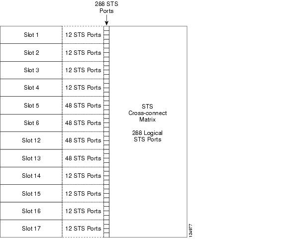
The XC card has 12 input ports and 12 output ports. Four input and output ports operate at either STS-12 or STS-48 rates. The remaining eight input and output ports operate at the STS-12 rate. An STS-1 on any of the input ports can be mapped to an STS-1 output port, thus providing full STS-1 time slot assignments (TSA). Figure 2-7 is a block diagram of the XC cross-connect matrix.
Figure 2-7 XC Cross-Connect Matrix
Point-to-multipoint connections are used for drop and continue sites in path protection and BLSR nodes. It is very important to note that when creating point-to-multipoint connections, the ratio of ports-to-connections is not 2:1, as it is in point-to-point cross-connections. Therefore, when calculating capacities, count terminating STS ports, not connections. When creating a point-to-point circuit, "Connection A," from Slot 1/Port 3/STS 2 (1/3/2) to Slot 2/Port 2/STS 4, consumes 2 ports. Creating a point-to-multipoint circuit, "Connection B," where Slot 2/Port 2/STS 2 maps to Slot 4/Port 4/STS 4 and Slot 5/Port 5/STS 5, consumes 3 ports. Subtracting the sum of Connection A (2 ports) and Connection B (3 ports) yields 288 - 5 = 283 logical ports remaining on the STS cross-connect. If these were unidirectional flows, Connection A would use 1 port and Connection B would use 1.5 ports. Unidirectional connections can be measured in .5 increments, because the cross-connect views a bi-directional flow as 2 unidirectional connections. An STS-1 on any input port can be mapped to any output port. Therefore the STS cross-connect is non-blocking, because it has the capacity to switch all 288 ports and STSs to all 288 ports and STSs.
XCVT Cross-Connect Card
The XCVT has all of the STS cross-connect functions that the XC does, including the Virtual Tributary (VT) tunneling. The XCVT provides non-blocking STS-48 capacity to all of the high-speed slots and non-bidirectional blocking STS-12 capacity to all multispeed slots. Any STS-1 on any port can be connected to any other port, meaning that the STS cross-connections are non-blocking.
The STS-1 switch matrix on the XCVT card consists of 288 bidirectional ports and adds a VT matrix that can manage up to 336 bidirectional VT1.5 ports or the equivalent of a bidirectional STS-12. The VT1.5 cross-connect matrix is used when mapping VT1.5 signals from one STS to multiple STSs, or performing TSI on the VT1.5s. The VT1.5 signals can be cross-connected, dropped, or rearranged. The switch matrices are fully cross-point and broadcast supporting. If VTs are tunneled as in the XC, they do not pass through the VT1.5 cross-connect matrix. Figure 2-8 is a block diagram of XCVT cross-connect matrix.
Figure 2-8 XCVT Cross-Connect Matrix
XC-10G Cross-Connect Card
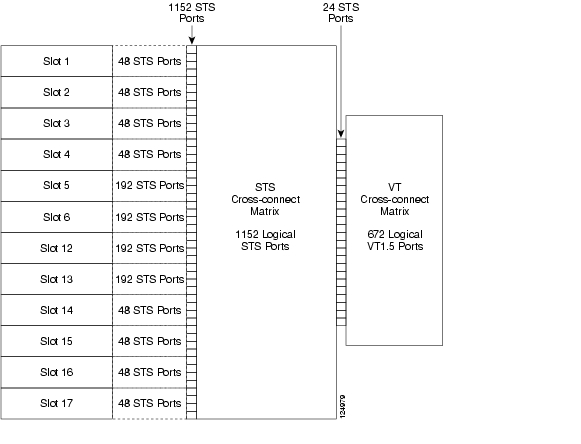
The XC10G is required for OC-192 transport. It has all the STS cross-connect and VT cross-connect functions as the XCVT, but supports four times the STS bandwidth of the XC and XCVT cards. The switch matrix on the XC10G card has 1152 bidirectional STS ports capable of supporting 576 STS cross-connect. The XC10G also includes a VT switch matrix consisting of 672 bidirectional VT1.5 ports capable of supporting up to 336 bidirectional VT1.5 cross-connects. As with the XC and XCVT cards, the XC10G card also supports VT tunneling. There are with 24 of those ports available for VT1.5 switching. Figure 2-9 is a block diagram of the XC10G cross-connect matrix.
Figure 2-9 XC10G Cross-Connect Matrix
I/O Interfaces Cross-Connect Capabilities
Twelve card slots, 1 through 6 and 12 through 17, hold multi-service interface cards. These slots are commonly referred to as I/O slots. Table 2-15 shows the cross-connect capability of each I/O slot on the Cisco ONS 15454.
VT1.5 Cross-Connects
The XC-VT and XC-10G cards can each map up to 24 STS ports for VT1.5 traffic. Because one STS can carry 28 VT1.5s, the XC-VT and XC-10G cards can terminate up to 672 VT1.5s, or 336 VT1.5 cross-connects. You must meet the following requirements to terminate 336 VT1.5 cross-connects:
•
•
Table 2-16 shows the VT1.5 and VT Tunnel capacities for ONS 15454 cross-connect cards. All capacities assume each VT1.5-mapped STS carries 28 VT1.5 circuits.
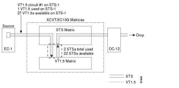
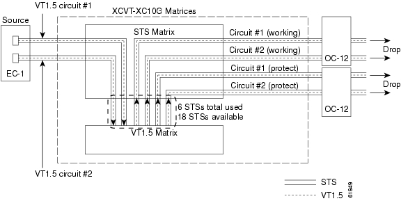
Figure 2-10 shows the logical flow of a VT1.5 circuit through the XCVT and XC-10G STS and VT1.5 matrices at a BLSR node. The circuit source is an EC-1 card using STS-1. After the circuit is created:
•
•
•
Figure 2-10 Example of a VT1.5 Circuit in a BLSR
When calculating the VT cross-connect capacity, it is not important to count VT1.5 connections or VT1.5 ports. Instead, count the number of STS ports terminating on the VT1.5 matrix because the terminations on the VT1.5 matrix are STS-based, not VT-based. In an STS that needs VT1.5 cross-connecting, even if an STS is only partially filled, every VT1.5 in the STS is terminated on the VT1.5 matrix. Like the STS matrix, the VT1.5 matrix is also non-blocking. Even when every VT1.5 in an STS is used, and all of the STS ports are consumed on the VT1.5 matrix, there is enough capacity on the VT1.5 matrix to switch every VT1.5 in every terminated STS. Therefore, it is important to count STS terminations instead of VT 1.5 terminations.
The number of STS ports in the VT1.5 matrix is 24. When those 24 ports are consumed, no additional VT1.5s can have access to the VT cross-connect matrix.
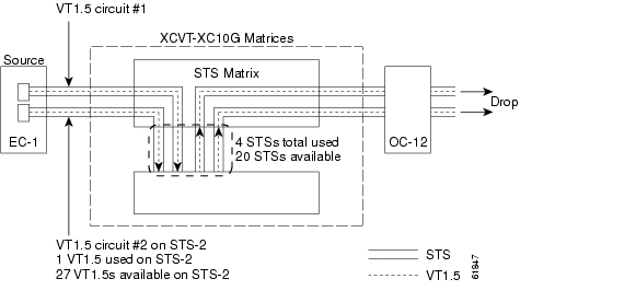
In Figure 2-11, a second VT1.5 circuit is created from the EC-1 card example illustrated in Figure 2-10. In this example, the circuit is assigned to STS-2:
•
•
•
Figure 2-11 Example of Two VT1.5 Circuits in a BLSR
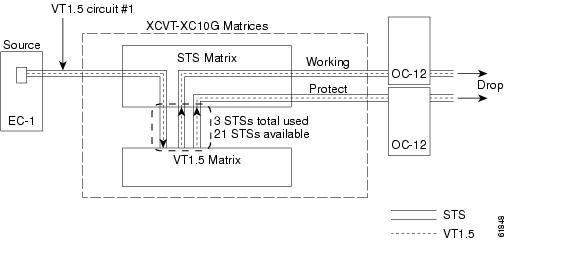
If you create VT1.5 circuits on nodes in path protection or 1+1 protection, an additional STS port is used on the VT1.5 matrix for the protect path at the source and drop nodes. Figure 2-12 shows a VT1.5 circuit at a path protection source node. When the circuit is completed:
•
•
Figure 2-12 Example of a VT1.5 Circuit in a Path Protection or 1+1 Protected Network
Figure 2-13 shows a second VT1.5 circuit that was created using STS-2. When the second VT1.5 circuit is created:
•
•
Figure 2-13 Example of Two VT1.5 Circuits in a Path Protection or 1+1 Protected Network
Unless you create VT tunnels, VT1.5 circuits use STS ports on the VT1.5 matrix at each node that the circuit passes through.
•
•
With Release 5.0 support for VT 1+1 protection increases from 224 to 336 VTs. The CTC Resource Allocation Usage screen is updated to display the working and protect allocation.
VT Tunnels
To maximize VT1.5 matrix resources, you can tunnel VT1.5 circuits through ONS 15454 pass-through nodes (nodes that are not a circuit source or drop). The number of VT tunnels that each ONS 15454 node can support is directly related to the cross-connect capacity of the STS matrix (see Table 2-16). VT1.5 tunnels provide the following benefits:
•
•
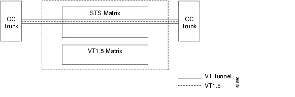
Figure 2-14 shows a VT tunnel through the XC-VT and XC-10G cross-connect matrices. No VT1.5-mapped STSs are used by the tunnel, which can carry 28 VT1.5s. However, the tunnel does use 2 STS matrix ports on each node through which it passes.
Figure 2-14 Example of a VT Tunnel
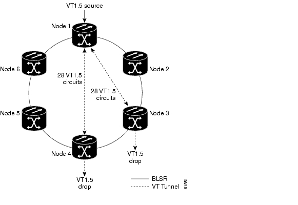
Figure 2-15 shows a six-node ONS 15454 ring with two VT tunnels. One tunnel carries VT1.5 circuits from Node 1 to Node 3. The second tunnel carries VT1.5 circuits from Node 1 to Node 4. Table 2-17 shows the STS usage on the VT 1.5 matrix at each node in a ring based on a given protection scheme and use of VT tunnels. In the Figure 2-15 example, the circuits travel clockwise (east) through Nodes 2, 3, and 4. Subsequently, STS usage on the VT1.5 matrix at these nodes is greater than at Nodes 5 and 6.
Figure 2-15 Example of a Six Node Ring with Two VT Tunnels
When planning VT1.5 circuits, weigh the benefits of using tunnels with the need to maximize STS capacity. For example, a VT1.5 tunnel between Node 1 and Node 4 passing (transparently) through Nodes 2 and Node 3 is advantageous if a full STS is used for Node 1 to Node 4 VT1.5 traffic (that is, the number of VT1.5 circuits between these nodes is close to 28). A VT tunnel is required if:
•
•
However, if the Node 1 to Node 4 tunnel carries a few VT1.5 circuits, creating a regular VT1.5 circuit between Nodes 1, 2, 3, and 4 might maximize STS capacity.
When you create a VT1.5 circuit during provisioning, the Cisco Transport Controller (CTC) determines whether a tunnel already exists between source and drop nodes. If a tunnel exists, CTC checks the tunnel capacity. If the capacity is sufficient, CTC routes the circuit on the existing tunnel. If a tunnel does not exist, or if an existing tunnel does not have sufficient capacity, CTC displays a dialog box asking whether you want to create a tunnel. Before you create the tunnel, review the existing tunnel availability, keeping in mind future bandwidth needs. In some cases, you may want to manually route a circuit rather than create a new tunnel.
VT Mapping
The VT structure is designed to transport and switch payloads below the DS3 rate. The ONS 15454 performs VT mapping according to Telcordia GR-253-CORE. Table 2-18 shows the VT numbering scheme for the ONS 15454 as it relates to the Telcordia standard.
VT Aggregation Point (VAP)
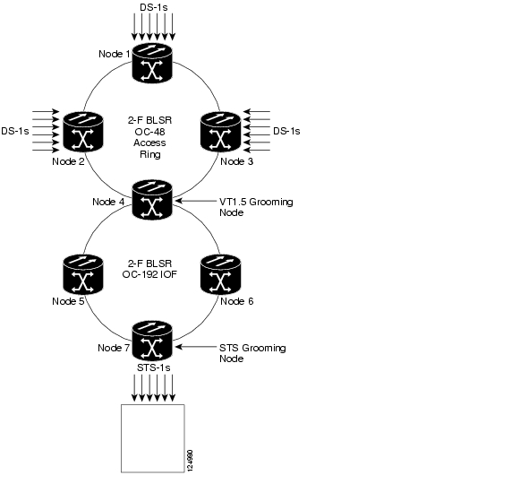
Starting with System Release 4.0, VT aggregation point (VAP) is a provisioning option only if you are creating DS-1 (VT1.5) circuits where the circuit source or destination is on an EC-1, DS3XM-6, DS3XM-12, or OC-N port on a BLSR, 1+1, or unprotected node. The VAP aggregates VT1.5s from multiple sources onto a single STS at a VT grooming node. The STS grooming node is the destination node where the STS containing the aggregated VT1.5s will be dropped off to either non-ONS 15454 networks or equipment, such as a switch or DACS (see Figure 2-16). VAPs allow VT1.5 circuits packed into a single STS to be routed through intermediate nodes located between the VAP grooming node and VAP destination node, without using any of the intermediate nodes' VT1.5 cross-connect ports. This saves VT1.5 matrix resources at the intermediate nodes.
Figure 2-16 VT Aggregation Point (VAP)
Note
The maximum number of VAPs that you can create depends on the node protection topology and number of VT1.5 circuits that terminate on the node. Assuming no other VT1.5 circuits terminate at the node, the maximum number of VAPs that you can terminate at one node is 8 for 1+1 and path protection and 12 for BLSR protection.
Circuits
You can create circuits across and within ONS 15454 nodes and assign different attributes to circuits. For example, you can:
•
•
•
•
•
•
•
•
•
You can provision circuits at any of the following points:
•
•
•
Circuit Properties
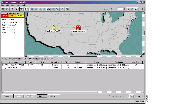
The ONS 15454 Circuits window, which appears in network, node, and card view, is where you can view information about circuits. The Circuits window, shown in Figure 2-17, provides the following information:
•
•
•
•
•
•
•
•
•
•
•
•
•
Figure 2-17 ONS 15454 Circuit Window in Network View
Circuit Status
The circuit statuses that appear in the Circuit window Status column are generated by CTC based on conditions along the circuit path. Table 2-19 shows the statuses that can appear in the Status column.
Circuit States
The circuit state is the status of all the cross-connect states within the circuit. The Release 5.0 circuit creation wizard uses the new node default value, CTC.circuits.state, as the default circuit state when creating a circuit. This default can be set in the NE Defaults window, and will not be overridden by the "sticky" command feature, which caused the default value to be abandoned when using the circuit provisioning wizard in previous software releases.
A circuit can be in one of the following states:
•
•
•
The state of a VCAT circuit is an aggregate of its member circuits. An In Group member has cross-connects in the IS-NR; OOS-MA,AINS; or OOS-MA,MT service states. An Out of Group member has cross-connects in the OOS-MA,DSBLD or OOS-MA,OOG service states. You can view whether a VCAT member is In Group or Out of Group in the VCAT State column on the Edit Circuits window. VCAT circuits can be in one of the following states:
•
•
•
•
You can assign a state to circuit cross-connects at two points:
•
•
During circuit creation, you can apply a service state to the drop ports in a circuit; however, CTC does not apply a requested state other than IS-NR to drop ports if:
•
•
•
•
Circuits do not use the soak timer, but ports do. The soak period is the amount of time that the port remains in the OOS-AU,AINS service state after a signal is continuously received. When the cross-connects in a circuit are in the OOS-AU,AINS service state, the ONS 15454 monitors the cross-connects for an error-free signal. It changes the state of the circuit from OOS to IS or to OOS-PARTIAL as each cross-connect assigned to the circuit path is completed. This allows you to provision a circuit using TL1, verify its path continuity, and prepare the port to go into service when it receives an error-free signal for the time specified in the port soak timer. Two common examples of state changes you see when provisioning circuits using CTC are:
•
•
To find the remaining port soak time, choose the Maintenance > AINS Soak tabs in card view and click the Retrieve button. If the port is in the OOS-AU,AINS state and has a good signal, the Time Until IS column shows the soak count down status. If the port is OOS-AU,AINS and has a bad signal, the Time Until IS column indicates that the signal is bad. You must click the Retrieve button to obtain the latest time value.
Circuit Protection Types
The Protection column on the Circuit window shows the card (line) and SONET topology (path) protection used for the entire circuit path. Table 2-20 shows the protection type indicators that appear in this column.
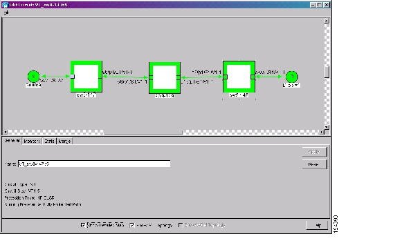
Circuit Information in the CTC Edit Circuit Window
The detailed circuit map on the CTC Edit Circuit window allows you to view information about ONS 15454 circuits. Routing information that appears includes the following:
•
•
•
•
•
•
You can also view alarms and states on the circuit map, including the following:
•
•
•
•
•
•
•
Figure 2-18 shows a VT circuit routed on a four-fiber BLSR.
Figure 2-18 BLSR Circuit Displayed on the Detailed Circuit Map
By default, the working path is indicated by a green, bidirectional arrow, and the protect path is indicated by a purple, bidirectional arrow. Source and destination ports are shown as circles with an S and D. Port states are indicated by colors, shown in Table 2-21.
Table 2-21 Port State Color Indicators
Green
IS-NR
Gray
OOS-MA,DSBLD
Violet
OOS-AU,AINS
Blue (Cyan)
OOS-MA,MT
A notation within or by the squares in detailed view indicates switches and loopbacks, including:
•
•
•
•
Move the mouse cursor over nodes, ports, and spans to see tooltips with information including the number of alarms on a node (organized by severity), port service state, and the protection topology. Right-click a node, port, or span on the detailed circuit map to initiate the following circuit actions:
•
•
•
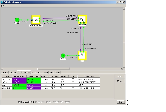
Figure 2-19 shows an example of the information that can appear. From this example, you can determine:
•
•
•
•
•
•
•
•
•
From the example, you could perform the following actions:
•
•
•
Figure 2-19 Detailed Circuit Map Showing a Terminal Loopback
VCAT Circuits
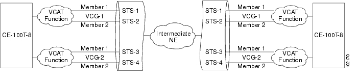
Virtual concatenated (VCAT) circuits, also called VCAT groups (VCGs), transport traffic using noncontiguous time division multiplexing (TDM) timeslots, avoiding the bandwidth fragmentation problem that exists with contiguous concatenated circuits. The cards that support VCAT circuits are the CE-100T-8, FC_MR-4 (both line rate and enhanced mode), and ML-Series cards.
In a VCAT circuit, circuit bandwidth is divided into smaller circuits called VCAT members. The individual members act as independent TDM circuits. All VCAT members should be the same size and must originate/terminate at the same end points. At the terminating nodes, these member circuits are multiplexed into a contiguous stream of data. Intermediate ONS 15454 nodes treat the VCAT members as normal circuits that are independently routed and protected by the SONET network. For two-fiber BLSR configurations, some members can be routed on protected time slots and others on PCA time slots. If a member is unprotected, all members must be unprotected. Path protection is not supported.
VCAT Circuit Size
Table 2-22 lists supported circuit rates and number of members for each card.
Table 2-22 ONS 15454 Card VCAT Circuit Rates and Members
CE-100T-8
VT1.5
1-64
STS-1
1-31
FC_MR-4 (line rate mode)
STS-1
24 (1Gbps port)
48 (2Gbps port)
STS-3c
8 (1Gbps port)
16 (2Gbps port)
FC_MR-4 (enhanced mode)
STS-1
1-24 (1Gbps port)
1-48 (2Gbps port)
STS-3c
1-8 (1Gbps port)
1-16 (2Gbps port)
ML-Series
STS-1, STS-3c, STS-12c
2
1 A VCAT circuit with a CE-100T-8 card as a source or destination and an ML-Series card as a source or destination can have only two members.
Use the Members tab on the CTC Edit Circuit window to add or delete members from a VCAT circuit. The capability to add or delete members depends on the card and whether the VCAT circuit is LCAS, Sw-LCAS, or non-LCAS.
•
•
•
•
Table 2-23 summarizes the VCAT capabilities for each card.
VCAT Member Routing
The automatic and manual routing selection applies to the entire VCAT circuit, that is, all members are manually or automatically routed. Bidirectional VCAT circuits are symmetric, which means that the same number of members travel in each direction. With automatic routing, you can specify the constraints for individual members; with manual routing, you can select different spans for different members.
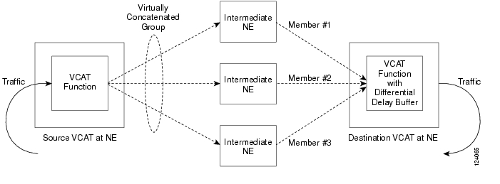
Two types of automatic and manual routing are available for VCAT members: common fiber routing and split routing. CE-100T-8, FC_MR-4 (both line rate and enhanced mode), and ML-Series cards support common fiber routing. In common fiber routing, all VCAT members travel on the same fibers, which eliminates delay between members. Three protection options are available for common fiber routing: Fully Protected, PCA, and Unprotected.
CE-100T-8 cards also support split fiber routing, which allows the individual members to be routed on different fibers or each member to have different routing constraints. This mode offers the greatest bandwidth efficiency and also the possibility of differential delay, which is handled by the buffers on the terminating cards. Four protection options are available for split fiber routing: Fully Protected, PCA, Unprotected, and DRI.
In both common fiber and split fiber routing, each member can use a different protection scheme; however, for common fiber routing, CTC checks the combination to make sure a valid route exists. If it does not, the user must modify the protection type. In both common fiber and split fiber routing, intermediate nodes treat the VCAT members as normal circuits that are independently routed and protected by the SONET network. At the terminating nodes, these member circuits are multiplexed into a contiguous stream of data. Figure 2-20 shows an example of common fiber routing and Figure 2-21 shows an example of split fiber routing.
Figure 2-20 VCAT on Common Fiber
Figure 2-21 VCAT Split Fiber Routing
LCAS
The CE-100T-8 card supports Link Capacity Adjustment Scheme (LCAS), which is a signaling protocol that allows dynamic bandwidth adjustment of VCAT circuits. When a member fails, a brief traffic hit occurs. LCAS temporarily removes the failed member from the VCAT circuit for the duration of the failure, leaving the remaining members to carry the traffic. When the failure clears, the member circuit is automatically added back into the VCAT circuit without affecting traffic. You can select LCAS during VCAT circuit creation.
Note
Instead of LCAS, the FC_MR-4 (enhanced mode) and ML-Series cards support Software-Link Capacity Adjustment Scheme (Sw-LCAS). Sw-LCAS is a limited form of LCAS that allows the VCAT circuit to adapt to member failures and keep traffic flowing at a reduced bandwidth. Sw-LCAS uses legacy SONET failure indicators like AIS-P and RDI-P to detect member failure. Sw-LCAS removes the failed member from the VCAT circuit, leaving the remaining members to carry the traffic. When the failure clears, the member circuit is automatically added back into the VCAT circuit. For ML-Series cards, Sw-LCAS allows circuit pairing over two-fiber BLSRs. With circuit pairing, a VCAT circuit is set up between two ML-Series cards; one is a protected circuit (line protection) and the other is PCA. For four-fiber BLSR, member protection cannot be mixed. You select Sw-LCAS during VCAT circuit creation. The FC_MR-4 (line rate mode) does not support Sw-LCAS.
In addition, you can create non-LCAS VCAT circuits, which do not use LCAS or Sw-LCAS. While LCAS and Sw-LCAS member cross-connects can be in different service states, all In Group non-LCAS members must have cross-connects in the same service state. A non-LCAS circuit can mix Out of Group and In Group members, as long as the In Group members are in the same service state. Non-LCAS members do not support the OOS-MA,OOG service state; to put a non-LCAS member in the Out of Group VCAT state, use OOS-MA,DSBLD.
Note
Portless Transmux Circuits
The DS3XM-12 card provides a portless transmux interface to change DS-3s into VT1.5s. For XC-VT drop slots (1-4 or 14-17), the DS3XM-12 card provides a maximum of 6 portless transmux interfaces. For XC-VT trunk slots and XC-10G any slots, the DS3XM-12 card provides a maximum of 12 portless transmux interfaces. If a pair of ports are configured as portless transmux, CTC allows you to create a DS3/STS1 circuit using one of these ports as the circuit end point. You can create separate DS1/VT1.5 circuits (up to 28) using the other port in this portless transmux pair.
Table 2-24 lists the portless transmux mapping for Slots 1-4 and 14-17 with the XC-VT cross-connect (STS-12).
Table 2-24 Portless Transmux Mapping with the XCVT
1-4 or 14-17
1, 2
13, 14
3, 4
15, 16
4, 6
17, 18
7, 8
19, 20
9, 10
21, 22
11, 12
23, 24
Table 2-25 lists the portless transmux mapping for Slots 5-6 and 12-13 with the XCVT cross-connect (STS-48).
Table 2-26 lists the portless tranmux mapping for Slots 1-6 and 12-17 with the XC10G cross-connect (STS-48).
Table 2-26 Portless Transmux Mapping with the XC10G
1
13, 14
2
25, 26
3
15, 16
4
27, 28
5
17, 18
6
29, 30
7
19, 20
8
31, 32
9
21, 22
10
33, 34
11
23, 24
12
35, 36
Multiple Destinations for Unidirectional Circuits
Unidirectional circuits can have multiple destinations for use in broadcast circuit schemes. In broadcast scenarios, one source transmits traffic to multiple destinations, but traffic is not returned to the source.
When you create a unidirectional circuit, the card that does not have its backplane receive (Rx) input terminated with a valid input signal generates a loss of signal (LOS) alarm. To mask the alarm, create an alarm profile suppressing the LOS alarm and apply the profile to the port that does not have its Rx input terminated.
Monitor Circuits
Monitor circuits are secondary circuits that monitor traffic on primary bidirectional circuits. At Node 1, a VT1.5 is dropped from Port 1 of an EC1-12 card. To monitor the VT1.5 traffic, plug test equipment into Port 2 of the EC1-12 card and provision a monitor circuit to Port 2. Circuit monitors are one-way. The monitor circuit in Figure 2-22 monitors VT1.5 traffic received by Port 1 of the EC1-12 card.
Figure 2-22 VT1.5 Monitor Circuit Received at an EC1-12 Port
Note
Test Access
The test access feature allows a third-party broadband remote test unit (BRTU) to create non-intrusive test access points (TAPs) to monitor the circuits on the ONS 15454 for errors. The test access feature also allows the circuit to be split (intrusive), so that the transmission paths can be tested for bit errors via the use of various bit test patterns. The two BRTUs supported by the ONS 15454 are the Hekimian/Spirent BRTU-93 (6750) and the TTC/Acterna Centest 650.
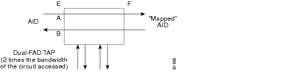
A test access point (TAP) provides the capability of connecting the circuit under test to a BRTU. This connection initially provides in-service monitoring capability to permit the tester to determine that the circuit under test is idle. The monitor connection should not disturb the circuit under test. The access point and BRTU also provide the capability of splitting a circuit under test. A split consists of breaking the transmission path of the circuit under test. This is done out of service. The two sides of the access point are called the Equipment (E) and Facility (F) directions. For a 4-wire or 6-wire circuit, the transmission pairs within the access point are defined as the A and B pairs. In Figure 2-23, the circuit under test should be wired into the access point so the direction of transmission on the A pair is from E to F, and the transmission direction for the B pair is from F to E.
Figure 2-23 Circuit With No Access Dual FAD TAP
A dual FAD (facility access digroup) TAP uses twice the bandwidth of the circuit under test. This can be specified by the TAPTYPE parameter in the ED-<MOD2> command. The values are SINGLE/DUAL. It defaults to DUAL.
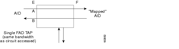
A single FAD TAP uses half the bandwidth as that of the dual FAD i.e., it will use the same bandwidth as the circuit accessed for the TAP creation. This can be specified by the TAPTYPE parameter. The values are SINGLE/DUAL. The MONEF, SPLTEF, LOOPEF modes are not supported by Single FAD TAPs (see Figure 2-24).
Figure 2-24 Circuit With No Access Single FAD TAP
Use TL1 commands for creating and deleting TAPs, connecting or disconnecting TAPs to circuit cross-connects and changing the mode of test access on the ONS 15454. You can view test access information in CTC, from in node view click the Maintenance > Test Access tabs.
When you provision a port to be a test access port, the next immediate port should be available and is automatically selected to be part of the Test Access Pair (TAP). In the example below, only the VT1-3-1-1-1 is explicitly entered in the command, but since TAP's are provisioned in pairs, the 15454, automatically selects VT1-3-1-2-1 also, to be part of this TAP #1. Refer to the Cisco ONS SONET TL1 Command Guide for the TL1 commands to create, delete, connect, change, retrieve, and disconnect TAPs.
•
–
•
–
•
–
•
–
Note
Path Protection Circuits
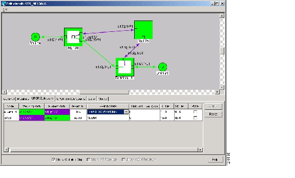
Use the CTC Edit Circuits window to change path protection selectors and switch protection paths (see Figure 2-25). In the UPSR Selectors subtab on the Edit Circuits window, you can:
•
•
•
•
•
Note
In the UPSR Switch Counts subtab, you can:
•
•
Figure 2-25 Editing Path Protection Selectors
Open-Ended Path Protection Circuits
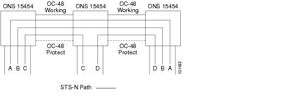
If ONS 15454 nodes are connected to a third-party network, you can create an open-ended path protection circuit to route a circuit through it. To do this, you create three circuits. One circuit is created on the source ONS 15454 network. This circuit has one source and two destinations, one at each ONS 15454 that is connected to the third-party network. The second circuit is created on the third-party network so that the circuit travels across the network on two paths to the ONS 15454s. That circuit routes the two circuit signals across the network to ONS 15454 nodes that are connected to the network on other side. At the destination node network, the third circuit is created with two sources, one at each node connected to the third-party network. A selector at the destination node chooses between the two signals that arrive at the node, similar to a regular path protection circuit.
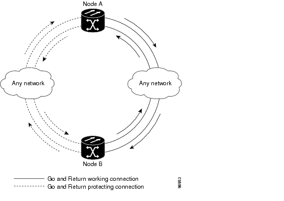
Go-and-Return Path Protection Routing
The go-and-return path protection routing option allows you to route the path protection working path on one fiber pair and the protect path on a separate fiber pair (see Figure 2-26). The working path will always be the shortest path. If a fault occurs, both the working and protection fibers are not affected. This feature only applies to bidirectional path protection circuits. The go-and-return option appears on the Circuit Attributes panel of the Circuit Creation wizard.
Figure 2-26 Path Protection Go-and-Return Routing
BLSR Protection Channel Access Circuits
You can provision circuits to carry traffic on BLSR protection channels when conditions are fault-free. Traffic routed on BLSR protection channel access (PCA) circuits, called extra traffic, has lower priority than the traffic on the working channels and has no means for protection. During ring or span switches, PCA circuits are preempted and squelched. For example, in a two-fiber OC-48 BLSR, STSs 25-48 can carry extra traffic when no ring switches are active, but PCA circuits on these STSs are preempted when a ring switch occurs. When the conditions that caused the ring switch are remedied and the ring switch is removed, PCA circuits are restored. If the BLSR is provisioned as revertive, this occurs automatically after the fault conditions are cleared and the reversion timer has expired.
Traffic provisioning on BLSR protection channels is performed during circuit provisioning. The Protection Channel Access check box appears whenever Fully Protected Path is unchecked on the circuit creation wizard. Refer to the Cisco ONS 15454 Procedure Guide for more information. When provisioning PCA circuits, two considerations are important to keep in mind:
•
•
Automatic Circuit Routing
If you select automatic routing during circuit creation, CTC routes the circuit by dividing the entire circuit route into segments based on protection domains. For unprotected segments of circuits provisioned as fully protected, CTC finds an alternate route to protect the segment, creating a virtual path protection. Each segment of a circuit path is a separate protection domain. Each protection domain is protected in a specific protection scheme including card protection (1+1, 1:1, etc.) or SONET topology (path protection, BLSR, etc.).
The following list provides principles and characteristics of automatic circuit routing:
•
•
•
•
•
•
•
Bandwidth Allocation and Routing
Within a given network, CTC routes circuits on the shortest possible path between source and destination based on the circuit attributes, such as protection and type. CTC considers using a link for the circuit only if the link meets the following requirements:
•
•
•
If CTC cannot find a link that meets these requirements, an error appears.
The same logic applies to VT circuits on VT tunnels. Circuit routing typically favors VT tunnels because VT tunnels are shortcuts between a given source and destination. If the VT tunnel in the route is full (no more bandwidth), CTC asks whether you want to create an additional VT tunnel.
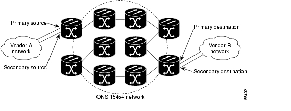
Secondary Sources and Destination
CTC supports secondary circuit sources and destinations (drops). Secondary sources and destinations typically interconnect two third-party networks, as shown in Figure 2-27. Traffic is protected while it goes through a network of ONS 15454 nodes.
Figure 2-27 Secondary Sources and Destinations
Several rules apply to secondary sources and destinations:
•
•
•
•
For bidirectional circuits, CTC creates a path protection connection at the source node that allows traffic to be selected from one of the two sources on the ONS 15454 network. If you check the Fully Path Protected option during circuit creation, traffic is protected within the ONS 15454 network. At the destination, another path protection connection is created to bridge traffic from the ONS 15454 network to the two destinations. A similar but opposite path exists for the reverse traffic flowing from the destinations to the sources.
For unidirectional circuits, a path protection drop-and-continue connection is created at the source node.
Manual Circuit Routing
Routing circuits manually allows you to:
•
•
•
•
CTC imposes the following rules on manual routes:
All circuits, except multicard EtherSwitch circuits in a shared packet ring, should have links with a direction that flows from source to destination. This is true for multicard EtherSwitch circuits that are not in a shared packet ring.
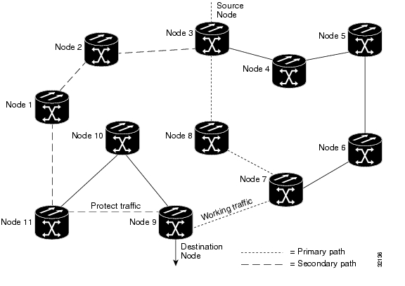
If you enabled Fully Path Protected, choose a diverse protect (alternate) path for every unprotected segment ( Figure 2-28).
Figure 2-28 Alternate Paths for Virtual Path Protection Segments
When you create circuits, you can choose Fully Protected Path to protect the circuit from source to destination. The protection mechanism used depends on the path CTC calculates for the circuit. If the network is composed entirely of BLSR or 1+1 links, or the path between source and destination can be entirely protected using 1+1 or BLSR links, no path-protected mesh network (PPMN), or virtual path protection, protection is used.
If PPMN protection is needed to protect the path, set the level of node diversity for the PPMN portions of the complete path on the Circuit Routing Preferences area of the Circuit Creation dialog box from the following options:
•
•
•
When you choose automatic circuit routing during circuit creation, you have the option to require or exclude nodes and links in the calculated route. You can use this option to achieve the following results:
•
•
CTC considers required nodes and links to be an ordered set of elements. CTC treats the source nodes of every required link as required nodes. When CTC calculates the path, it makes sure the computed path traverses the required set of nodes and links and does not traverse excluded nodes and links.
The required nodes and links constraint is only used during the primary path computation and only for PPMN domains/segments. The alternate path is computed normally; CTC uses excluded nodes/links when finding all primary and alternate paths on PPMNs.
TL1-Like Circuits
You can create cross-connects with CTC, like you would with TL1 commands by selecting the Create TL1-Like option before creating a circuit. The TL1-Like option instructs the ONS 15454 node to create only cross-connects and places the resulting circuits in an UPGRADABLE state. This state allows you upgrade circuits created with the TL1-Like option to be converted to CTC circuits, if desired.
Merge Circuits
A circuit merge combines a single selected circuit with one or more circuits. You can merge tunnels, VAP circuits, VLAN-assigned circuits, CTC-created circuits, and TL1-created circuits. To merge circuits, you choose a circuit on the CTC Circuits tab window and the circuits that you want to merge with the chosen (master) circuit on the Merge tab in the Edit Circuits window. The Merge tab shows only the circuits that are available for merging with the master circuit:
•
•
•
•
•
•
•
If all connections from the master circuit and all connections from the merged circuits align to form one complete circuit, the merge is successful. If all connections from the master circuit and some, but not all, connections from the other circuits align to form a single complete circuit, CTC notifies you and gives you the chance to cancel the merge process. If you choose to continue, the aligned connections merge successfully into the master circuit, and unaligned connections remain in the original circuits.
All connections from the master circuit and at least one connection from the other selected circuits must be used in the resulting circuit for the merge to succeed. If a merge fails, the master circuit and all other circuits remain unchanged. When the circuit merge completes successfully, the resulting circuit retains the name of the master circuit.
Reconfigure Circuits
You can reconfigure multiple circuits, which is typically necessary when a large number of circuits are in the PARTIAL status. When reconfiguring multiple circuits, the selected circuits can be any combination of DISCOVERED, PARTIAL, DISCOVERED_TL1, or PARTIAL_TL1 circuits. You can reconfigure tunnels, VAP circuits, VLAN-assigned circuits, CTC-created circuits, and TL1-created circuits.
Use the CTC Tools > Circuits > Reconfigure Circuits command to reconfigure selected circuits. During reconfiguration, CTC reassembles all connections of the selected circuits into circuits based on path size, direction, and alignment. Some circuits might merge and others might split into multiple circuits. If the resulting circuit is a valid circuit, it appears as a DISCOVERED circuit. Otherwise, the circuit appears as a PARTIAL or PARTIAL_TL1 circuit.
TL1-CTC Circuit Unification
In Release 5.0 CTC fully supports TL1-created circuits and TL1 fully supports CTC-created circuits. Release 5.0 circuit behavior and appearance is unified across both management interfaces, and you can easily alternate between the two. It is also no longer necessary to upgrade a TL1 circuit for CTC, or to downgrade a CTC circuit for TL1. The following circuit unification enhancements are supported with Release 5.0:
•
•
•
•
•
•
•
•
•
•
•
•
•
•
•
Synchronization and Timing
Network synchronization and timing are critical elements within a SONET network. The goal is to create a fully synchronous optical hierarchy by ensuring that all ONS 15454 nodes derive timing traceable to a primary reference source (PRS). An ONS 15454 network may use more than one PRS. A PRS is equipment that provides a timing signal whose long-term accuracy is maintained at 10-11 or better with verification to Universal Time Coordinated (UTC), and whose timing signal is used as the basis of reference for the control of other clocks within a network.
Network Clock Sources
A stratum 1 timing source is typically the Primary Reference Source (PRS) within a network, because it ensures the highest level of performance of a SONET network. Other types of clocks used in the synchronized network include stratum 2, 3E, 3, 4E, and 4, In most cases these clocks are components of a digital synchronization network and are synchronized to other clocks within that network using a hierarchical master-slave arrangement. In this arrangement, each clock receives timing, usually in the form of primary and secondary reference signals, from another clock of the same or better quality. Figure 2-29 shows the timing accuracy hierarchy supported by the ONS 15454.
Figure 2-29 ONS 15454 Timing Hierarchy
The clocks used to synchronize ONS 15454 nodes must be stratum 3 (or better quality) to meet ANSI T1.101 synchronization requirements.
Building Integrated Timing Supply (BITS)
In the United States, a Building Integrated Timing Supply (BITS) clock is commonly used to distribute timing signals from Stratum clocks to an ONS 15454 node. BITS timing references run over the working and protect SONET paths.
Cesium Clock
Local Cesium clocks (often referred to as atomic clocks) can also be used to provide stratum 1 quality synchronization. The advantage of a Cesium clock is that it never needs recalibration. However, the cost for each unit is very high.
Global Positioning System (GPS)
Compared to Cesium clocks, the Navstart Global Positioning Satellites provide a lower cost alternative source for network synchronization. These satellites are accessible throughout North America and have internal cesium clocks that can be used as a Stratum 1 source. A GPS receiver costs much less than a Cesium clock.
Synchronous Status Messaging (SSM)
Synchronization status messaging (SSM) is a SONET protocol that communicates information about the quality of the timing source. SSM messages are carried on the S1 byte of the SONET Line layer. They enable SONET devices to automatically select the highest quality timing reference and to avoid timing loops.
SSM messages are either Generation 1 or Generation 2. Generation 1 is the first and most widely deployed SSM message set. Generation 2 is a newer version. If you enable SSM for the ONS 15454, refer to Chapter 7 to determine which message set to use.
In the SONET protocol, SSM is carried in the S1 byte of the SONET line overhead. SSM enables SONET devices to automatically select the highest quality timing reference and helps to avoid timing loops. If the timing signal is lost on the active path, the NE switches to an alternate path for timing according to the SSM hierarchy.
The BITS signal is a DS-1 level, 1.544 MHz signal, formatted either as Superframe (SF) with 12 frames per superframe, or the Extended Superframe (ESF) with 24 frames per extended superframe. SF is also referred to as D4 framing. For BITS sources, SSM is supported by messages embedded into the 4 kbps, 'Facility Data Link' of DS-1 ESF signals. SSM is not available with DS-1 SF (D4) signals. In the SF (D4) mode, the AIS signal (unframed 'all-ones') indicates an unsuitable reference.
Protection Switching
Optical protection switching occurs automatically in response to detected faults, as well as manual requests initiated by local or remote users. The Cisco ONS 15454 supports 50 milliseconds (ms) 1+1 unidirectional or bi-directional protection switching upon detecting a signal failure or condition such as LOS, LOF, AIS-L or high BER on one or more of the optical card's ports. Revertive and nonrevertive switching options are available down to the circuit level.
The SONET protection modes supported by the Cisco ONS 15454 are described in Table 2-27.
Table 2-27 SONET Protection Modes
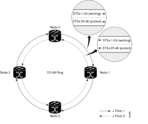
Unidirectional
Each ONS 15454 node bridges it's transmit information on the working and protect lines. When traffic is switched from a bad line, only the receiving node performs a switch. The APS channel (which is carried in the K1 and K2 bytes of the signal on the protection line) is used to indicate the local switch action and the mode of operation. Path protection is the default mode for 1+1 protection groups in the ONS 15454.
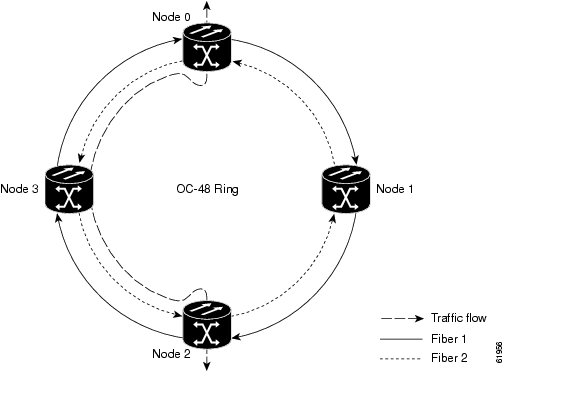
Bidirectional
Each ONS 15454 node monitors it's receive bit stream on the currently active path. When a problem is detected, both nodes transfer their transmit bit stream to the protection line. Switching of only one direction is not allowed. Head end to tail end signaling is accomplished using the APS channel. The ONS 15454 Bi-directional Line Switched Ring (BLSR) protection mode is configured by the user during initial turn up of the ring.
Revertive
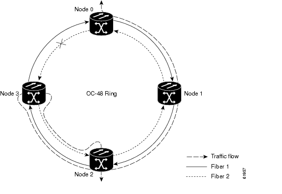
In revertive mode, a failure is detected and the working line temporarily switches to the protect line using the K1/K2 bytes. When the working line is restored and meets the BER criteria, a wait-to-restore (WTR) timer is initiated in the ONS 15454 to prevent "switch bouncing." Traffic is switched back to the working line at both ONS 15454 nodes when the working line has recovered from the failure and the WTR interval has been met, or the manual switch command is cleared. Traffic will revert back to the working line again using the K1/K2 bytes. Revertive protection is illustrated in Table 2-33.
Nonrevertive
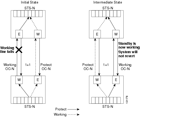
In nonrevertive mode, the ONS 15454 detects a failure and switches the working line to the protect line using the K1/K2 bytes. The protect line now becomes the working line and the previous working line will become the protect line. If the line that failed is restored, traffic will not switch back. There is no WTR setting for non-revertive switching. Traffic will not be switched back unless the current working line develops trouble. Nonrevertive protection is illustrated in Figure 2-31.
Path Protection Switching
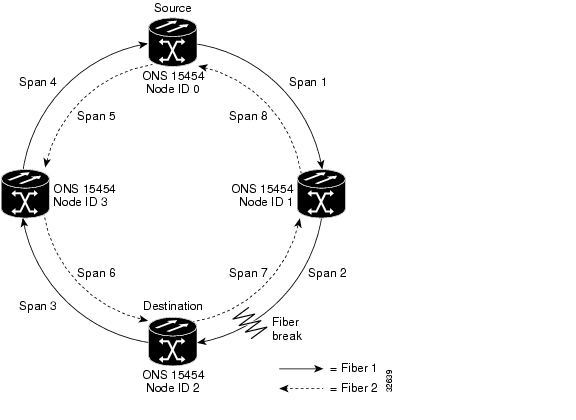
Path protection switching in an ONS 15454 system means, first, discovering that the active path is no longer performing as desired, and second, switching the payload to an alternate path that is flawless (or at least better than the active path). In the STS Path level protection example shown in Figure 2-30, the path signal is bridged or split at the "head end" or at the source. Two copies of the signal are transmitted to the destination point, where the receiver selects the best signal based on Path level parameters (B3 and AIS). STS Path switching is automatically initiated by any of the following conditions:
•
•
•
•
•
Figure 2-30 STS Path Switching
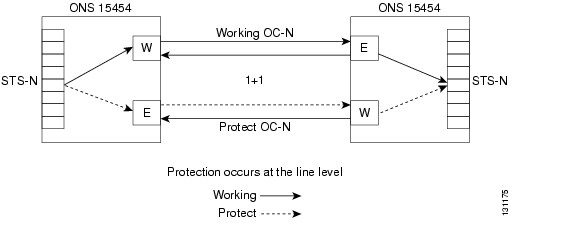
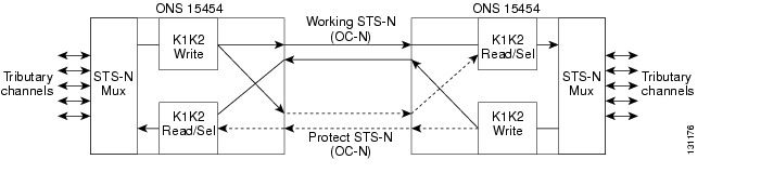
Line Protection Switching
The Line protection switching example shown in Figure 2-31, a single copy of the signal goes through the working line of the system. If the working line fails, then traffic will switch over to protection using line layer parameters (K1, K2, and B2). The ONS 15454 will automatically initiate a Line protection switch if any of the following conditions occur:
•
•
•
•
Figure 2-31 Line Protection Switching
Automatic Protection Switching
Automatic Protection Switching (APS) is switching that is initiated by the ONS 15454 based on built-in algorithms, assisted by Performance Management (PM) threshold settings and protection options stored in the TCC2/TCC2P database. The first setting stored in the TCC2/TCC2P is the type of SONET OC-N cards that have been installed in the ONS 15454 (i.e., OC-3, OC-12, OC-48, OC-192). Each OC-N port has two pre-selected thresholds for protection switching: Signal Fail (SF) and Signal Degrade (SD).
SF is a "hard failure" condition detected on the incoming OC-N signal. The ONS 15454 monitors the bit error rate (BER) on the incoming OC-N signal and will switch to the protect span if the BER exceeds 1E-3 (one bit error in 1,000 bits) or if the ONS 15454 detects a Loss of Signal (LOS), Loss of Frame (LOF), or Alarm Indication Signal (AIS). If a span goes into the SF condition, the ONS 15454 will switch traffic to the protect span, even if that span is in the SD condition. The BER default threshold setting is 1E-4 (one bit error in 10,000 bits), but it may be changed to 1E-3 or 1E-5.
SD is a "soft failure" condition resulting from the Line BER exceeding 1E-6. When the ONS 15454 detects a BER exceeding 1E-6 on the incoming OC-N, it will announce the SD condition on that line and switch away from it, if possible. The BER default setting is 1E-7 (one bit error in 10,000,000 bits), but it may be changed to 1E-5, 1E-6, 1E-8 or 1E-9.
Other protection settings to be entered into the TCC2/TCC2P database include the type of protection and whether the protection is unidirectional, bi-directional, revertive, or non-revertive, and reversion time in minutes (if revertive is chosen). APS is illustrated in Figure 2-32.
Figure 2-32 APS Example
1+1 Protection Switching
Any OC-N card can use 1+1 protection. With 1+1 port-to-port protection, ports on the protect card can be assigned to protect the corresponding ports on the working card. The working and protect cards do not have to be placed side by side in the node. A working card must be paired with a protect card of the same type and number of ports. For example, a single-port OC-12 must be paired with another single-port OC-12, and a four-port OC-12 must be paired with another four-port OC-12. You cannot create a 1+1 protection group if one card is single-port and the other is multiport, even if the OC-N rates are the same. The protection takes place on the port level, and any number of ports on the protect card can be assigned to protect the corresponding ports on the working card.
For example, on a four-port card, you can assign one port as a protection port on the protect card (protecting the corresponding port on the working card) and leave three ports unprotected. Conversely, you can assign three ports as protection ports and leave one port unprotected. In other words, all the ports on the protect card are used in the protection scheme.
1+1 span protection can be either revertive or nonrevertive. Revertive 1+1 protection automatically switches the signal back to the working card when the working card comes back online (see Figure 2-33). With nonrevertive 1+1 protection, when a failure occurs and the signal switches from the working card to the protect card, the signal stays switched to the protect card until it is manually switched back (see Figure 2-34). 1+1 protection is unidirectional and nonrevertive by default; revertive switching is easily provisioned using CTC.
Figure 2-33 Revertive Switching
Figure 2-34 Nonrevertive Switching
Optimized 1+1 Protection
Optimized 1+1 protection is used in networks that mainly use the linear 1+1 bidirectional protection scheme. Optimized 1+1 is a line-level protection scheme using two lines, working and protect. One of the two lines assumes the role of the primary channel, where traffic is selected, and the other line assumes the role of secondary channel, which protects the primary channel. Traffic switches from the primary channel to the secondary channel based on either line conditions or an external switching command performed by the user. After the line condition clears, the traffic remains on the secondary channel. The secondary channel is automatically renamed as the primary channel and the former primary channel is automatically renamed as the secondary channel.
Unlike 1+1 span protection, 1+1 optimized span protection does not use the revertive or nonrevertive feature. Also, 1+1 optimized span protection does not use the Manual switch command. The 1+1 optimized span protection scheme is supported only on the Cisco ONS 15454 using either OC3-4 cards or OC3-8 cards with ports that are provisioned for SDH payloads.
With optimized 1+1 port-to-port protection, ports on the protect card can be assigned to protect the corresponding ports on the working card. The working and protect cards do not have to be installed side by side in the node. A working card must be paired with a protect card of the same type and number of ports. For example, a four-port OC-3 must be paired with another four-port OC-3, and an eight-port OC-3 must be paired with another eight-port OC-3. You cannot create an optimized 1+1 protection group if the number of ports do not match, even if the OC-N rates are the same.
The protection takes place on the port level, and any number of ports on the protect card can be assigned to protect the corresponding ports on the working card. For example, on a four-port card, you can assign one port as a protection port on the protect card (protecting the corresponding port on the working card) and leave three ports unprotected. Conversely, you can assign three ports as protection ports and leave one port unprotected.
External Switching Commands
The external switching commands on the ONS 15454 are Manual, Force, and Lockout. If you choose a Manual switch, the command will switch traffic only if the path has an error rate less than the signal degrade (SD) bit error rate threshold. A Force switch will switch traffic even if the path has SD or signal fail (SF) conditions; however, a Force switch will not override an SF on a 1+1 protection channel.
A Force switch has a higher priority than a Manual switch. Lockouts, which prevent traffic from switching to the protect port under any circumstance, can only be applied to protect cards (in 1+1 configurations) . Lockouts have the highest priority. In a 1+1 configuration you can also apply a lock on to the working port. A working port with a lock on applied cannot switch traffic to the protect port in the protection group (pair). In 1:1 protection groups, working or protect ports can have a lock on.
Note
Dual-Ring Interconnect—Path Protection
In System Release 4.0, the ONS 15454 will support path protection dual-ring interconnection (DRI), which provides added path-level protection for both VT1.5 and STS circuits. The ONS 15454 conforms to the dual interconnected ring architecture defined in Telcordia GR-1400-CORE. Traffic is dropped and continued at the interconnecting nodes to eliminate single points of failure. Two DRI topologies can be implemented on the ONS 15454. The traditional DRI uses four ONS 15454 nodes to interconnect the two rings, while the integrated DRI only uses two ONS 15454 nodes.
Figure 2-35 shows ONS 15454 nodes in a traditional dual ring interconnect topology. In Ring number 1, Nodes 3 and 4 are the interconnect nodes, and in Ring 2, Nodes 6 and 10. Duplicate signals are sent from Node 3 (Ring 1) to Node 6 (Ring 2), and between Node 4 (Ring 1) and Node 10 (Ring 2). In Ring number1, traffic at Node 3 is dropped (to Node 6) and continued (to Node 4). Similarly, at Node 4, traffic is dropped (to Node 10) and continued (to Node 5).
Figure 2-35 Traditional Dual Ring Interconnect
Figure 2-36 shows ONS 15454 nodes in an integrated dual ring interconnect topology. The same drop and continue traffic routing occurs at two nodes, rather than four. This is achieved by installing an addition OC-N trunk at the two interconnect nodes as illustrated in Figure 2-37.
Figure 2-36 Integrated Dual Ring Interconnect
Figure 2-37 Integrated Path Protection Fiber Connections
Dual Ring Interconnect—BLSR
Unlike BLSR automatic protection switching (APS) protocol, BLSR-DRI is a path-level protection protocol at the circuit level. Drop-and-continue BLSR-DRI requires a service selector in the primary node for each circuit routing to the other ring. Service selectors monitor signal conditions from dual feed sources and select the one that has the best signal quality. Same-side routing drops the traffic at primary nodes set up on the same side of the connected rings, and opposite-side routing drops the traffic at primary nodes set up on the opposite sides of the connected rings. For BLSR-DRI, primary and secondary nodes cannot be the circuit source or destination.
Note
DRI protection circuits act as protection channel access (PCA) circuits. In CTC, you set up DRI protection circuits by selecting the PCA option when setting up primary and secondary nodes during DRI circuit creation.
Figure 2-38 shows ONS 15454 nodes in a traditional BLSR-DRI topology with same-side routing. In Ring 1, Nodes 3 and 4 are the interconnect nodes, and in Ring 2, Nodes 8 and 9 are the interconnect nodes. Duplicate signals are sent between Node 4 (Ring 1) and Node 9 (Ring 2), and between Node 3 (Ring 1) and Node 8 (Ring 2). The primary nodes (Nodes 4 and 9) are on the same side, and the secondary nodes (Nodes 3 and 8) provide an alternative route. In Ring 1, traffic at Node 4 is dropped (to Node 9) and continued (to Node 10). Similarly, at Node 9, traffic is dropped (to Node 4) and continued (to Node 5).
Figure 2-38 ONS 15454 Traditional BLSR Dual-Ring Interconnect (Same-Side Routing)
Figure 2-39 shows ONS 15454 nodes in a traditional BLSR-DRI topology with opposite-side routing. In Ring 1, Nodes 3 and 4 are the interconnect nodes, and in Ring 2, Nodes 8 and 9 are the interconnect nodes. Duplicate signals are sent from Node 4 (Ring 1) to Node 8 (Ring 2), and between Node 3 (Ring 1) and Node 9 (Ring 2). In Ring 1, traffic at Node 4 is dropped (to Node 9) and continued (to Node 8). Similarly, at Node 8, traffic is dropped (to Node 3) and continued (to Node 4).
Figure 2-39 ONS 15454 Traditional BLSR Dual-Ring Interconnect (Opposite-Side Routing)
Figure 2-40 shows ONS 15454 nodes in an integrated BLSR-DRI topology. The same drop-and-continue traffic routing occurs at two nodes, rather than four. This is achieved by installing an addition OC-N trunk at the two interconnect nodes. Nodes 3 and 8 are the interconnect nodes.
Figure 2-40 ONS 15454 Integrated BLSR Dual-Ring Interconnect
Protection Switch Initiation Time
The switch initiation time is the time that it takes the ONS 15454 to detect a SF or SD condition and initiate a switch (if appropriate). The switch initiation time criteria listed below are not applicable for manually initiated switches. Manual switches initiated by the user can take longer to initiate.
For SF conditions caused by LOS, LOF, or AIS defects, the ONS 15454 will initiate a switch in 10 ms or less.
For SD condition caused by LOS, LOF, or AIS defects, the ONS 15454 will initiate a switch in 8 ms or less.
For SF and SD conditions based on BER, the switch initiation time will vary, because the occurrence of errors on an OC-N signal is generally random. The ONS 15454 will initiate a switch when the actual BER is greater than or equal to the SF and SD thresholds set for the particular rate of the span's OC-N signal.
Protection Switch Completion Time
An ONS 15454 operating in a network comprised of ONS 15454 nodes configured for APS or 1+1 protection will complete a switch in 50 ms or less, once it is initiated automatically by the ONS 15454 or manually by the user.
In network configurations made up of nodes from different suppliers, the overall switch time may be greater than 50 ms. This situation exists, because each supplier's node must perform various actions before a switch can be completed. Since the algorithms and methods used by suppliers vary for switching, it may take longer for the protection switch to complete.
Node Latency
Use the formulas below to calculate the latency through an ONS 15454 node. Input and output times for the multi-service interfaces are given below the formulas. Insert those times into the formulas to get the overall latency through a node for various configurations. For example, an STS-1 circuit coming in on a DS-3 card and leaving on an OC-48 card will have a latency calculation of: 7 micro seconds + 1 micro second + 3.5 micro seconds = 11.5 micro seconds. The general latency formulas are as follows:
•
•
The latency for each of the multi-service cards is as follows:
•
•
•
•
•
•
Network Topologies
There are several ways that ONS 15454 nodes may be connected together to form a network. The ONS 15454 supports point-to-point terminals, linear add/drop multiplexers, path protection, two-fiber and four-fiber bidirectional line switched rings (BLSRs), subtending rings, path protected mesh network (PPMN), and virtual rings.
Terminal Mode
In a terminal mode (TM) topology, the entire SONET payload is terminated at each end of the fiber span. The nodes are connected by four fibers in protected configurations. Protection spans can be added by installing another trunk card, such as an OC-48, or by using additional ports on a multiport optical card, such as an OC-3 or OC-12. TM systems are generally deployed for basic transport applications calling only for a single system solution routed point-to-point. Figure 2-41 shows the traffic flow for a typical TM configuration.
Figure 2-41 Terminal Network Traffic Flow
Figure 2-42 shows the node configuration for a protected point-to-point TM ONS 15454 network. Working traffic flows from Node 1/Slot 6 to Node 2/Slot 6. The protect path runs from Node 1/Slot 5 to Node 2/Slot 5.
Figure 2-42 Terminal Node Network Configuration
Linear Add/Drop Multiplexer Network
Any ONS 15454 node can be designed as an add/drop multiplexer (ADM) and provide add/drop for DS1, DS3, EC-1, OC-3, OC-12, and OC-48 signals as shown in Figure 2-43. A linear ADM ONS 15454 system can be provisioned for unidirectional or bi-directional OC-N line switching. In unidirectional switching, the OC-N receiver can switch independently from the OC-N transmitter. In bi-directional switching, the OC-N transmitter and receiver switch as a pair. The 1+1 line switching is nonrevertive for either case.
Figure 2-43 Three Node Linear ADM Network
When used in a Linear ADM configuration, each ONS 15454 has direct access to Westbound or Eastbound STS channels at intermediate sites along the fiber route. Cisco ONS 15454 ADM configurations eliminate the need for costly "back-to-back" terminal nodes, and can be enhanced with protection spans for any OC-N rate. Figure 2-44 shows the traffic flow for a typical linear ADM network. Each ONS 15454 node requires four fibers, working and protect optical transmitters and receivers in both directions, and local drops for insertion and termination of any signal in the route.
Figure 2-44 Linear ADM Traffic Flow
Path Protection
Path protection is the default topology used for connecting ONS 15454 nodes together. Path protection configuratoions provide duplicate fiber paths around the ring. Working traffic flows in one direction and protection traffic flows in the opposite direction. If a problem occurs in the working traffic path, the receiving node switches to the path coming from the opposite direction. Because each traffic path is transported around the entire ring, path protection configurations are best suited for networks where traffic concentrates at one or two locations and is not widely distributed. path protection capacity is equal to its bit rate. Services can originate and terminate on the same path protection, or they can be passed to an adjacent access or interoffice ring for transport to the service-terminating location.
Path protection design requirements for the ONS 15454 are based on the path protection criteria listed in Telcordia GR-1400-CORE. It is a survivable, closed-loop design that survives cable cuts and equipment failure by providing duplicate fiber paths for each service. The ONS 15454 supports path protection functionality on the OC-3, OC-12, OC-48, and OC-192 cards. Starting in System Release 4.6 you can have up to a maximum of 34 path protection configurations on a single ONS 15454. With Releases 4.0 and 4.1, you can have up to a maximum of 16 path protection configurations on a single ONS 15454 node. Systems prior to Release 4.0 can have a maximum of 5 path protection configurations on a single node. Table 2-28 shows the maximum number of path protection configurations that can be created on a single ONS 15454 node.
Table 2-28 Protection Modes
>= Release 4.6
34
>= Release 4.0
16
<= Release 3.4
5
Path protection traffic is defined within the ONS 15454 on a circuit-by-circuit basis. If a path-protected circuit is not defined within a 1+1 or Bi-directional Line Switched Ring (BLSR) line protection scheme and path protection is available and specified, CTC uses path protection as the default. Each circuit path may be provisioned for revertive or non-revertive switching. The ONS 15454 default is non-revertive. If you choose revertive switching, the default wait-to-restore (WTR) time is 5 minutes. This default setting may be changed from 0.5 - 12 minutes if needed. Network element (NE) default settings can be modified as needed.
Figure 2-45 shows a basic path protection network. Working and protect traffic are routed over separate fiber paths in opposite directions. For example, if Node ID 0 sends a signal to Node ID 2, the working signal travels on the working traffic path through Node ID 1. The same signal is also sent on the protect traffic path through Node ID 3. Each span uses STS-1 bandwidth capacity along the entire circumference of the ring. If a fiber break occurs as shown in Figure 2-46, Node ID 2 switches its active receiver to the protect signal coming through Node ID 3.
Figure 2-45 Path Protection Network
Figure 2-46 Path Protection with a Fiber Break
Only two OC-N trunk cards are required per node for the SONET span. This design saves network equipment costs as opposed to a linear design where each intermediate node needs four OC-N trunk cards for 1+1 protection. A Cisco ONS 15454 path protection node consists of the following cards for each node within the network:
•
•
•
•
Figure 2-47 shows the typical SONET configuration for each ONS 15454 node in a path protection network.
Figure 2-47 Path Protection Node Configuration
The West Working OC-N facility is physically cabled to the East Working OC-N facility of the adjacent ONS 15454 node. Figure 2-48 shows the fiber routes for a 4 node path protection.
Figure 2-48 Routing Fiber for a Path Protection
Path protection designs are very common in the metropolitan area. In Figure 2-46, note that the working traffic between nodes travels clockwise (East to West) over spans 1, 2, 3, and 4. Traffic from a user on Node 1 to a user on Node 2 uses the path: Node 1-to-Span 1-to-Node 2 for two-way communication. Traffic from a user on Node 2 to a user on Node 1 uses path: Node 2-to-Span-2-to-Span-3-to-Span-4-to-Node 1. Spans 5, 6, 7, and 8 are not used for working traffic. They are used when one of the working spans fails. Traffic on these spans travels counter-clockwise (West to East). For each STS-N circuit, each end node will transmit the bit stream both ways around the ring. The receiving node will monitor both bit streams, and choose to receive from the bit stream with the lower bit error rate. If both streams are error-free, one or the other may be chosen, depending on settings. Should a fiber cut affecting traffic in one direction, the other direction acts as protection.
Common Path Protection Application
The access network application shown in Figure 2-49 requires most of its traffic to run between customer locations and an end office or point-of-presence (POP). In this common path protection application, OC-3 optics provide remote switch connectivity to a host TR-303 switch. In the example, each ONS 15454 node requires 8 DS-1s to return to the host switch. Figure 2-50 and Figure 2-51 show the shelf layout for each node.
Figure 2-49 OC-3 Path Protection Access Network
Node ID 0 has three DS1-14 cards (two working, and one protect) to provide 24 active DS-1 ports. The other nodes only require two DS1-14 cards (one working and one protect) to handle the eight DS-1s to and from the remote switch. You can use the other half of each ONS 15454 node's shelf assembly to provide support for a second or third ring to other existing or planned remote sites.
In this sample OC-3 path protection, Node ID 0 contains 4 DS1-14 cards and 2 OC3 IR 4 1310 cards. Six free slots also exist in this setup and can be provisioned with cards or left empty. Figure 2-50 shows an efficient way to configure the ONS 15454 for these cards using only half of a shelf.
Figure 2-50 Layout of Node ID 0 in the OC-3 Path Protection
In the Figure 2-49, Nodes IDs 1 through 3 each contain 2 DS1-14 cards and 2 OC3 4 IR 1310 cards. Eight free slots exist. They can be provisioned with other cards or left empty. Figure 2-51 shows the shelf assembly setup for this configuration sample.
Figure 2-51 Layout of Nodes IDs 1-3 in the OC-3 Path Protection
Two-Fiber Bidirectional Path Switched Ring
A bidirectional line switched ring (BLSR) is a self-healing ring configuration used to connect two or more adjacent ONS 15454 nodes. The protected network design of a BLSR helps it survive cable cuts and node failures by providing redundant, geographically diverse paths for each SONET span. BLSR nodes can terminate traffic coming from either side of the ring. Therefore, BLSRs are suited for distributed node-to-node traffic applications such as interoffice networks and access networks.
The ONS 15454 BLSR functionality is based on criteria found in GR-1230-CORE. Since the flow of traffic between nodes is bi-directional, traffic can be added at one node and dropped at the next without traveling around the entire ring. This allows you to reuse the available STS bandwidth between the other nodes for additional traffic, thereby enabling a BLSR to carry more traffic than a path protection. Table 2-29 shows the bi-directional capacity for two-fiber BLSRs. The capacity is the OC-N rate divided by two, multiplied by the number of nodes in the ring minus the number of pass-through STS-1 circuits.
Table 2-29 Two-Fiber BLSR Capacities
OC-12
STS 1-6
STS 7-12
OC-48
STS 1-24
STS 25-48
24 x N 1 - PT
OC-192
STS 1-96
STS 97-192
96 x N 1 - PT
1 N equals the number of ONS 15454 nodes configured as BLSR nodes.
2 PT equals the number of STS-1 circuits passed through ONS 15454 nodes in the ring (capacity can vary depending on the traffic pattern).
Starting with System Release 3.4, you can use the protection capacity of a two-fiber BLSR to provide unprotected transport for extra traffic when no failures are present. Table 2-30 shows the maximum number of two-fiber BLSRs each ONS 15454 node can support.
Table 2-30 Maximum Number of Two-Fiber BLSRs Supported
>= Release 4.0
5
<= Release 4.0
2
Each of the two-fiber BLSR can have up to 32 ONS 15454 nodes. The supported BLSRs include OC-12, OC-48, and OC-192 only, because the working and protect bandwidths must be equal.
Note
The ONS 15454 automatically creates a squelch table when you provision BLSR circuits. The squelch table works at the STS-1 level. VT1.5 squelching will be supported in a future system release. It is important to remember that bandwidth reuse should not be done at the VT1.5 level. If a VT1.5 circuit passes between two ONS 15454 nodes within an assigned STS, that same VT1.5 bandwidth should not be used to form any other path around the BLSR. Not reusing that same VT1.5 bandwidth around the ring will avoid the potential for incorrect termination upon a protection switch, due to the lack of VT1.5 squelching.
Two-fiber BLSR is the most common topology used by Local Exchange Carriers (LECs) in major metropolitan areas. A two-fiber BLSR can provide protection against the failure of an individual fiber pair on the ring. The bi-directional operation of the BLSR provides symmetrical delay for data users. Since only two-fibers are used to close the ring, two-fiber BLSRs are economical to deploy.
In two-fiber BLSRs, each fiber is divided into working and protect bandwidths. In the OC-48 BLSR example shown in Figure 2-52, STSs 1 through 24 carry the working traffic, and STSs 25 through 48 are reserved for protection. Working traffic (STSs 1 - 24) travels in one direction on one fiber and in the opposite direction on the second fiber. Each BLSR must be assigned a unique Ring ID, which is a number between 0 and 9999. Nodes in the same BLSR must have the same Ring ID. Each node within a BLSR must be assigned a unique Node ID, which is a number between 0 and 31. CTC's circuit routing routines calculate the "shortest path" for circuits based on many factors, including requirements set by the circuit provisioner, traffic patterns, and distance. For example, in Figure 2-53, circuits going from Node 0 to Node 1 typically will travel on Fiber 1, unless that fiber is full, in which case circuits will be routed on Fiber 2 through Node 3 and Node 2. Traffic from Node 0 to Node 2 (or Node 1 to Node 3), may be routed on either fiber, depending on circuit provisioning requirements and traffic loads.
Figure 2-52 Four-Node, Two-Fiber BLSR
The SONET K1 and K2 bytes carry the information that governs BLSR protection switches. Each BLSR node monitors the K bytes to determine when to switch the SONET signal to an alternate physical path. The K bytes communicate failure conditions and actions taken between nodes in the ring. If a Cisco ONS 15454 BLSR span passes through third party equipment that cannot transparently transport the K3 byte, remap the BLSR extension byte on the trunk cards on each end of the span.
If a break occurs on one fiber, working traffic targeted for a node beyond the break switches to the protect bandwidth on the second fiber. The traffic travels in reverse direction on the protect bandwidth until it reaches its destination node. At that point, traffic is switched back to the working bandwidth. Figure 2-53 shows a sample traffic pattern on a four-node, two-fiber BLSR.
Figure 2-53 4-Node, 2-Fiber BLSR Sample Traffic Pattern
Figure 2-54 shows how traffic is rerouted following a line break between Node 0 and Node 3.
All circuits originating on Node 0 carried to Node 2 on Fiber 2 are switched to the protect bandwidth of Fiber 1. For example, a circuit carried on STS-1 on Fiber 2 is switched to STS-25 on Fiber 1. A circuit carried on STS-2 on Fiber 2 is switched to STS-26 on Fiber 1. Fiber 1 carries the circuit to Node 3 (the original routing destination). Node 3 switches the circuit back to STS-1 on Fiber 2 where it is routed to Node 2 on STS-1.
Circuits originating on Node 2 that were normally carried to Node 0 on Fiber 1 are switched to the protect bandwidth of Fiber 2 at Node 3. For example, a circuit carried on STS-2 on Fiber 1 is switched to STS-26 on Fiber 2. Fiber 2 carries the circuit to Node 0 where the circuit is switched back to STS-2 on Fiber 1 and then dropped to its destination.
Figure 2-54 4-Node, 2-Fiber BLSR Traffic Pattern Following Line Break
Four-Fiber BLSR
Four-fiber BLSRs double the bandwidth of two-fiber BLSRs. Because they allow span switching as well as ring switching, four-fiber BLSRs increase the reliability and flexibility of traffic protection. Two fibers are allocated for working traffic and two fibers for protection, as shown in Figure 2-55. To implement a four-fiber BLSR, you must install 4 OC-48 or OC-48AS cards, or 4 OC-192 cards at each BLSR node.
Table 2-31 shows the maximum number of four-fiber BLSRs each ONS 15454 node can support.
Table 2-31 Maximum Number of Four-Fiber BLSRs Supported
<= Release 4.0
1
Each four-fiber BLSR can have up to 32 ONS 15454 nodes. Because the working and protect bandwidths must be equal, you can create only OC-48, or OC-192 BLSRs. Table 2-32 shows the bi-directional bandwidth capacities of four-fiber BLSRs.
Table 2-32 Four-Fiber BLSR Capacities
OC-48
STS 1-48 (Fiber 1)
STS 1-48 (Fiber 2)
OC-192
STS 1-192 (Fiber 1)
STS 1-192 (Fiber 2)
192 x N 1 - PT
1 N equals the number of ONS 15454 nodes configured as BLSR nodes.
2 PT equals the number of STS-1 circuits passed through ONS 15454 nodes in the ring (capacity can vary depending on the traffic pattern).
Figure 2-55 Four-Node, Four-Fiber BLSR
Four-Fiber Span and Ring Switching
Cisco ONS 15454 four-fiber BLSRs provide span and ring switching as follows:
•
•
The K1 byte of the Line Overhead carries the bridge request and associated priorities. These priorities are used to determine if a bridge request can be fulfilled, when an existing ring or span switch is present on the four-fiber BLSR. Within the K1 byte, bits 1 through 4 define the "request pre-emption priority". Bits 5 through 7 of the K1 byte are designated for the Destination Node ID, and "indicate the node ID of the adjacent node to which the K1 byte is destined."
Figure 2-56 Four-Fiber BLSR Span Switch
Figure 2-57 Four-Fiber BLSR Ring Switch
BLSR Fiber Connections
Plan your fiber connections and use the same plan for all BLSR nodes. For example, make the East port the farthest slot to the right and the West port the farthest left. Plug fiber connected to an East port at one node into the West port on an adjacent node. Figure 2-58 shows fiber connections for a two-fiber BLSR with trunk cards in Slot 5 (West) and Slot 12 (East).
Figure 2-58 Connecting Fiber to a Four-Node, Two-Fiber BLSR
For four-fiber BLSRs, use the same East—West connection pattern for the working and protect fibers. Do not mix working and protect card connections. The BLSR will not function if working and protect cards are interconnected. Figure 2-59 shows fiber connections for a four-fiber BLSR. Slot 5 (West) and Slot 12 (East) carry the working traffic. Slot 6 (West) and Slot 13 (East) carry the protect traffic.
Figure 2-59 Connecting Fiber to a Four-Node, Four-Fiber BLSR
Subtending Rings
An ONS 15454 with redundant TCC2/TCC2P cards can supports up to 68 SONET DCCs. Table 2-33 shows the number of SONET rings that can be created on each ONS 15454 node using redundant TCC2/TCC2P cards.
Subtending rings from an ONS 15454 reduces the number of nodes and cards required and reduces external shelf-to-shelf cabling. Figure 2-60 shows an ONS 15454 network with multiple subtending rings.
Figure 2-60 ONS 15454 Network with Multiple Subtending Rings
Figure 2-61 shows a path protection subtending from a BLSR. In this example, Node 3 is the only node serving both the BLSR and path protection. OC-N cards in Slots 5 and 12 serve the BLSR, and OC-N cards in Slots 6 and 13 serve the path protection.
Figure 2-61 Path Protection Subtending from a BLSR
The ONS 15454 can support two BLSRs on the same node. This capability allows you to deploy an ONS 15454 in applications requiring SONET DCSs (digital cross-connect systems) or multiple SONET ADMs.
Figure 2-62 shows two BLSRs shared by one ONS 15454. Ring 1 runs on Nodes 1, 2, 3, and 4. Ring 2 runs on Nodes 4, 5, 6, and 7. Two BLSR rings, Ring 1 and Ring 2, are provisioned on Node 4. Ring 1 uses cards in Slots 5 and 12, and Ring 2 uses cards in Slots 6 and 13.
Although different node IDs are used for the two BLSRs shown in Figure 2-62, nodes in different BLSRs can use the same node ID.
Figure 2-62 BLSR Subtending from a BLSR
After subtending two BLSRs, you can route circuits from nodes in one ring to nodes in the second ring. For example in Figure 2-63, you can route a circuit from Node 1 to Node 7. The circuit would normally travel from Node 1 to Node 4 to Node 7. If fiber breaks occur between Nodes 1 and 4 and Nodes 4 and 7 as shown in Figure 2-63, traffic is rerouted around each ring to Nodes 2 and 3 in Ring 1 and Nodes 5 and 6 in Ring 2.
Figure 2-63 Two-Fiber Breaks in Subtending Rings
Path-Protected Meshed Networks
In addition to single BLSRs, path protection configurations and ADMs, you can extend ONS 15454 traffic protection by creating path-protected mesh networks (PPMNs). PPMNs include multiple ONS 15454 SONET topologies and extend the protection provided by a single path protection to the meshed architecture of several interconnecting rings. In a PPMN, circuits travel diverse paths through a network of single or multiple meshed rings. When you create circuits, you can have CTC automatically route circuits across the PPMN, or you can manually route them. You can also choose levels of circuit protection. For example, if you choose full protection, CTC creates an alternate route for the circuit in addition to the main route. The second route follows a unique path through the network between the source and destination and sets up a second set of cross-connections.
For example, in Figure 2-64, a circuit is created from Node 3 to Node 9. CTC determines that the shortest route between the two nodes passes through Node 8 and Node 7, shown by the dotted line, and automatically creates cross-connections at Nodes, 3, 8, 7, and 9 to provide the primary circuit path.
If full protection is selected, CTC creates a second unique route between Nodes 3 and 9 which, in this example, passes through Nodes 2, 1, and 11. Cross-connections are automatically created at Nodes 3, 2, 1, 11, and 9, shown by the dashed line. If a failure occurs on the primary path, traffic switches to the second circuit path. In this example, Node 9 switches from the traffic coming in from Node 7 to the traffic coming in from Node 11 and service resumes. The switch occurs within 50 ms.
Figure 2-64 Path-Protected Mesh Network
PPMN also allows spans of different SONET line rates to be mixed together in "virtual rings." Figure 2-65 shows Nodes 1, 2, 3, and 4 in a standard OC-48 ring. Nodes 5, 6, 7, and 8 link to the backbone ring through OC-12 fiber. The "virtual ring" formed by Nodes 5, 6, 7, and 8 uses both OC-48 and OC-12.
Figure 2-65 PPMN Virtual Ring
Inservice Topology Conversions
Caution
Topology conversions can be performed in-service to convert a live network to a different topology. The following in-service topology conversions are supported:
•
•
•
•
•
You can perform in-service topology conversions irrespective of the service state of the involved cross-connects or circuits, however a circuit must have a DISCOVERED status. For explanations on how to convert from one network topology to another, refer to the Cisco ONS 15454 Procedure Guide.
Circuit types supported for in-service topology conversions are:
•
•
•
•
•
•
•
You cannot upgrade stitched Ethernet circuits during topology conversions. For in-service topology conversion procedures, refer to the "Convert Network Configurations" chapter in the Cisco ONS 15454 Procedure Guide. For procedures to add or remove a node, refer to the "Add and Remove Nodes" chapter of the Cisco ONS 15454 Procedure Guide.
Note
Note
Unprotected Point-to-Point or Linear ADM to Path Protection
CTC provides a topology conversion wizard for converting an unprotected point-to-point or linear ADM topology to path protection. This conversion occurs at the circuit level. CTC calculates the additional path protection circuit route automatically or you can do it manually. When routing the path protection circuit, you can provision the USPR as go-and-return or unidirectional.
When performing an in-service topology conversion on a configuration with VCAT circuits, CTC allows you to select member circuits to upgrade individually. When upgrading VT tunnels, CTC does not convert the VT tunnel to path protection, but instead creates a secondary tunnel for the alternate path. The result is two unprotected VT tunnels using alternate paths.
To convert from point-to-point or linear ADM to a path protection, the topology requires an additional circuit route to complete the ring. When the route is established, CTC creates circuit connections on any intermediate nodes and modifies existing circuit connections on the original circuit path. The number and position of network spans in the topology remains unchanged during and after the conversion.
Figure 2-66 shows an unprotected point-to-point ADM configuration converted to a path protection. An additional circuit routes through Node 3 to complete the path protection.
Figure 2-66 Unprotected Point-to-Point ADM to Path Protection Conversion
Point-to-Point or Linear ADM to Two-Fiber BLSR
A 1+1 point-to-point or linear ADM to a two-fiber BLSR conversion is manual. You must remove the protect fibers from all nodes in the linear ADM and route them from the end node to the protect port on the other end node. In addition, you must delete the circuit paths that are located in the bandwidth that will become the protection portion of the two-fiber BLSR (for example, circuits in STS 25 or higher on an OC-48 BLSR) and recreate them in the appropriate bandwidth. Finally, you must provision the nodes as BLSR nodes.
To complete a conversion from an unprotected point-to-point or linear ADM to a two-fiber BLSR, use the CTC Convert Unprotected/path protection to BLSR wizard from the Tools > Topology Upgrade menu.
Path Protection to Two-Fiber BLSR
CTC provides a topology conversion wizard to convert a path protection to a two-fiber BLSR. A conversion from a path protection to a two-fiber BLSR changes path protection to line protection. A path protection can have a maximum of 16 nodes before conversion. Circuit paths must occupy the same time slots around the ring. Only the primary path through the path protection is needed; the topology conversion wizard removes the alternate path protection path during the conversion. Because circuit paths can begin and end outside of the topology, the conversion might create line-protected segments within path protection paths of circuits outside the scope of the ring. The physical arrangement of the ring nodes and spans remains the same after the conversion.
Two-Fiber BLSR to Four-Fiber BLSR
CTC provides a wizard to convert two-fiber OC-48 or OC-192 BLSRs to four-fiber BLSRs. To convert the BLSR, you must install two OC-48 or OC-192 cards at each two-fiber BLSR node, then log into CTC and convert each node from two-fiber to four-fiber. The fibers that were divided into working and protect bandwidths for the two-fiber BLSR are now fully allocated for working BLSR traffic.
Add or Remove a Node from a Topology
You can add or remove a node from a linear ADM, BLSR, or path protection configuration. Adding or removing nodes from BLSRs is potentially service affecting, however adding and removing nodes from an existing 1+1 linear ADM or path protection configuration does not disrupt traffic. CTC provides a wizard for adding a node to a point-to-point or 1+1 linear ADM. This wizard is used when adding a node between two other nodes.
SONET Span Upgrades
A span is the optical fiber connection between two ONS 15454 nodes. In a span (optical speed) upgrade, the transmission rate of a span is upgraded from a lower to a higher OC-N signal but all other span configuration attributes remain unchanged. With multiple nodes, a span upgrade is a coordinated series of upgrades on all nodes in the ring or protection group in which traffic carried at a lower OC-N rate is transferred to a higher OC-N. You can perform in-service span upgrades for the following ONS 15454 cards:
•
•
•
•
•
Table 2-34 lists permitted upgrades for Slots 5, 6, 12, and 13.
Table 2-34 Slot 5, 6, 12, and 13 Upgrade Options
Four-port OC-3
N/A
Not supported
Not supported
Not supported
Not supported
Not supported
Eight-port OC-31
Not supported
N/A
Not supported
Not supported
Not supported
Not supported
One-port OC-12
Not supported
Not supported
N/A
Not supported
Yes
Yes
Four-port OC-122
Not supported
Not supported
Not supported
N/A
Not supported
Not supported
OC-48
Not supported
Not supported
Yes
Not supported
N/A
Yes
OC-192
Not supported
Not supported
Yes
Not supported
Yes
N/A
1 The eight-port OC-3 is not supported in Slots 5, 6, 12, and 13.
2 The four-port OC-12 is not supported in Slots 5, 6, 12, and 13.
Table 2-35 lists permitted upgrades for Slots 1 through 4 and 14 through 17.
Note
To perform a span upgrade, the higher-rate optical card must replace the lower-rate card in the same slot. If the upgrade is conducted on spans residing in a BLSR, all spans in the ring must be upgraded. The protection configuration of the original lower-rate optical card (two-fiber BLSR, four-fiber BLSR, path protection, and 1+1) is retained for the higher-rate optical card.
When performing span upgrades on a large number of nodes, Cisco recommends that you upgrade all spans in a ring consecutively and in the same maintenance window. Until all spans are upgraded, mismatched card types will be present.
Cisco recommends using the Span Upgrade Wizard to perform span upgrades. Although you can also use the manual span upgrade procedures, the manual procedures are mainly provided as error recovery for the wizard. The Span Upgrade Wizard and the Manual Span Upgrade procedures require at least two technicians (one at each end of the span) who can communicate with each other during the upgrade. Upgrading a span is non-service affecting and will cause no more than three switches, each of which is less than 50 ms in duration.
Span Upgrade Wizard
The Span Upgrade Wizard automates all steps in the manual span upgrade procedure (BLSR, path protection, and 1+1). The wizard can upgrade both lines on one side of a four-fiber BLSR or both lines of a 1+1 group; the wizard upgrades path protection configurations and two-fiber BLSRs one line at a time. The Span Upgrade Wizard requires that spans have DCC enabled. For an explanation on how to use the Span Upgrade Wizard, refer to the Cisco ONS 15454 Procedures Guide.
The Span Upgrade Wizard provides no way to back out of an upgrade. In the case of an abnormal error, you must exit the wizard and initiate the manual procedure to either continue with the upgrade or back out of it. To continue with the manual procedure, examine the standing conditions and alarms to identify the stage in which the wizard failure occurred.
Note
Manual Span Upgrades
Manual Span Upgrades are mainly provided as error recovery for the Span Upgrade Wizard, but they can be used to perform span upgrades. Downgrading can be performed to back out of a span upgrade. The procedure for downgrading is the same as upgrading except that you choose a lower-rate card type. You cannot downgrade if circuits exist on the STSs that will be removed (the higher STSs).
The following manual span upgrade options are available the Cisco ONS 15454 Procedures Guide:
•
•
•
•
•
![]()
![]()
![]()
![]()
![]()
![]()
![]()
![]()
Posted: Tue Nov 27 11:14:37 PST 2007
All contents are Copyright © 1992--2007 Cisco Systems, Inc. All rights reserved.
Important Notices and Privacy Statement.