|
|

Table Of Contents
ONS 15454 Shelf Assemblies and Backplane Hardware
Electrical Interface Assemblies
ONS 15454 Plug-in Cards and Slot Requirements
ONS 15454 Common Control Cards
ONS 15454 GBIC and SFP Connectors
System Overview
Note
The terms "Unidirectional Path Switched Ring" and "UPSR" may appear in Cisco literature. These terms do not refer to using Cisco ONS 15xxx products in a unidirectional path switched ring configuration. Rather, these terms, as well as "Path Protected Mesh Network" and "PPMN," refer generally to Cisco's path protection feature, which may be used in any topological network configuration. Cisco does not recommend using its path protection feature in any particular topological network configuration.
This chapter provides an overview of the Cisco ONS 15454 and a list of new features for System Release 5.0.
The following topics are covered in this chapter:
•
•
•
•
•
•
•
•
Introduction to the ONS 15454
The Cisco ONS 15454 provides efficient bandwidth delivery and management in optical networks. It can be configured as a multi-service provisioning platform (MSPP), multi-service transport platform (MSTP), or hybrid MSPP/MSTP.
As an MSPP, the ONS 15454 is a flexible SONET add/drop multiplexer (ADM) that offers service aggregation and high-bandwidth transport of voice and data traffic in a single platform. It allows you to easily manage services and increase capacity without disrupting services. The ONS 15454 carries traditional time-division multiplexing (TDM) and high-speed data traffic over a single mode fiber optic system.
System Release 4.5 introduced ONS 15454 DWDM cards and ONS 15454 MSTP configuration that used the ONS 15454 shelf assembly to provide wavelength services and DWDM channel aggregation.
Consolidated software loads in Releases 4.6 and 5.0 allow you to deploy the ONS 15454 in a hybrid mode that supports both MSPP and MSTP configurations in a single chassis. The choice of multi-service aggregation, wavelength aggregation, and wavelength transport, combined with DWDM transmission in a single platform enables networks to be cost-optimized for any mix of services.
ONS 15454 Shelf Assemblies and Backplane Hardware
In this document, the terms "ONS 15454" and "shelf assembly" are used interchangeably. In the installation context, these terms have the same meaning. Otherwise, shelf assembly refers to the physical steel enclosure that holds cards and connects power, and ONS 15454 refers to the entire system, both hardware and software.
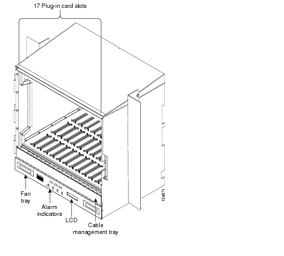
The ONS 15454 temperature-hardened 15454-SA-ANSI shelf assembly shown in Figure 1-1 contains 17 plug-in card slots, a backplane interface, a fan tray with LCD and alarm indicators, and a cable management tray. Starting with Release 4.6, the 15454-SA-HD (high-density) shelf assembly replaces the 15454-SA-ANSI as the default chassis for new installations. You can install both 15454-SA-ANSI and 15454-SA-HD the shelf assemblies in a 19- or 23-inch rack. Both shelf assemblies weigh approximately 42 pounds without mounting ears and plug-in cards.
Figure 1-1 Cisco ONS 15454 15454-SA-ANSI Shelf Assembly
When installed in an equipment rack, the shelf assembly is typically connected to a fuse and alarm panel to provide centralized alarm connection points and distributed power for the ONS 15454. Fuse and alarm panels are third-party equipment and are not covered in this document. The front door of the ONS 15454 allows access to the shelf assembly, fan tray, and cable management area. The shelf assembly can be installed in both EIA-standard or Telcordia-standard racks.
The ANSI and HD shelf assemblies are a total of 17 inches wide with no mounting ears attached. Ring runs are not provided by Cisco and may hinder side-by-side installation of shelves where space is limited. Both shelves measure 18.5 inches high and 19 or 23 inches wide (depending on which way the mounting ears are attached). The 15454-SA-ANSI shelf with the standard door measures 12 inches deep and 14 inches deep with the optional deep door. You can install up to four of the ANSI or HD shelves in a seven-foot equipment rack. Each shelf must have 1 inch of airspace between them to allow air flow to the fan intake. When a second shelf is installed, the air ramp on top of the lower shelf assembly provides the air spacing needed and should not be modified in any way.
The backplane provides access to alarm contacts, external interface contacts, power terminals, and BNC, SMB, AMP Champ, and SCSI connectors. The lower section of the ONS 15454 backplane is covered either by a clear plastic or metal protector.
Electrical Interface Assemblies
Optional electrical interface assemblies (EIAs) are attached to the shelf assembly backplane to provide electrical interface cable connections. EIA backplane covers are typically preinstalled when ordered with the ONS 15454. EIAs must be ordered when using DS-1, DS-3, DS3XM, or EC-1 cards.
Seven different EIA backplane covers are available for the ONS 15454: BNC, High-Density BNC, Mini-BNC, SMB, AMP Champ, Universal Backplane Interface Connector - Vertical (UBIC-V) and UBIC - Horizontal (UBIC-H). UBIC-V and UBIC-H backplane covers are typically preinstalled when ordered with the ONS 15454 high density shelf (15454-SA-HD). Either UBIC-V or UBIC-H EIAs are required when using the high-density (48-port DS-3/EC-1 and 56-port DS-1) electrical cards. If the shelf was not shipped with the correct EIA interface, you must order and install the correct EIA.
EIAs are available with SMB, BNC, Mini-BNC, UBIC-H, and UBIC-V connectors for DS-3, DS3XM (TMUX) or EC-1 cards. EIAs are available with AMP Champ, UBIC-H, and UBIC-V connectors for DS-1 cards. You must use SMB (with wire wrap Balun), UBIC-H or UBIC-V EIAs for DS-1 twisted-pair cable installation. You can install EIAs on one or both sides of the ONS 15454 backplane in any combination (in other words, AMP Champ on Side A and BNC on Side B or High-Density BNC on side A and UBIC-V on side B, and so forth).
As you face the rear of the ONS 15454 shelf assembly, the right side is the A side and the left side is the B side. The EIA connector columns are labeled transmit (Tx) and receive (Rx) to correspond to transmit and receive cables.
Alarm Expansion Panel
The ONS 15454 alarm expansion panel (AEP) is used with the Alarm Interface Card (AIC-I) card to provide 48 dry alarm contacts for the ONS 15454 system, 32 of which are inputs and 16 outputs. The AEP is a printed circuit board assembly that is installed on the backplane. Figure 1-2 shows the AEP board.
Figure 1-2 Alarm Expansion Panel
Cable Routing and Management
ONS 15454 optical cards have SC or small form LC connectors on the card faceplate. Ethernet cards have RJ45 connectors on the faceplate. Fiber optic and CAT 5 cables are routed into the front of the optical and Ethernet cards. Electrical cards (DS-1, DS-3, DS3XM, and EC-1) require EIAs to provide the cable connection points for the shelf assembly.
The ONS 15454 cable management facilities include the following:
•
•
•
•
•
•
•
•
•
Figure 1-3 shows the cable management facilities that you can access through the fold-down front door, including the cable-routing channel and the reversible jumper routing fins.
Figure 1-3 Managing Cables on the Front Panel
Figure 1-4 shows the optional universal cable-router inserts, which has round posts that allow you to route cables out either side of the cable-routing channel.
Figure 1-4 Universal Cable-Router Inserts
ONS 15454 Plug-in Cards and Slot Requirements
ONS 15454 cards have electrical plugs at the back that plug into electrical connectors on the shelf assembly backplane. When the ejectors are fully closed, the card plugs into the assembly backplane.
The ONS 15454 15454-SA-ANSI shelf assembly has 17 card slots numbered sequentially from left to right. Slots 1 through 4 and 14 through 17 are multispeed slots. They can host any ONS 15454 card, except the OC48IR/STM16 SH 1310, OC48LR/STM 16 LH 1550, OC48ELR 1550, and OC192LR/STM64LH 1550 cards. Slots 5, 6, 12 and 13 are high-speed slots, which can host all ONS 15454 cards except the OC3/STM-6 and OC12/STM4-4 card. You can install the OC48 IR/STM16 SH AS 1310 and the OC48 LR/STM16 LH AS 1550 cards in any multispeed or high-speed card slot. The 15454-SA-HD shelf assembly is the same as the 15454-SA-ANSI, except slots 1 to 3 and 15 to 17 can supports greater electrical termination capacities required for the high-density (HD) DS-1, DS-3, and EC-1 interface cards. The HD cards are planned for a future release. Slots 7 and 11 are dedicated to Timing, Comunication and Control (TCC) cards. Slots 8 and 10 are dedicated to cross-connect (XCVT, XC10G) cards. Slot 9 is reserved for the optional Alarm Interface Controller (AIC) card. Slots 3 and 15 can also host DS1N-14 and DS3N-12 cards that are used in 1:N protection.
Shelf assembly slots have symbols indicating the type of cards that you can install in them. Each ONS 15454 card has a corresponding symbol. You can only install cards in slots where the symbol on the card's faceplate matches the symbol on the slot. Table 1-1 shows the slot and card symbol definitions.
ONS 15454 Common Control Cards
Table 1-2 lists the six common control cards available for the Cisco ONS 15454 and summarizes their functions.
ONS 15454 Interface Cards
The ONS 15454 is architected for maximum flexibility. A single ONS 15454 shelf assembly supports a variety of card configurations and interfaces ranging from 1.5Mb/s to 10Gb/s as listed below in Table 1-3.
.
Table 1-3 List of Cisco ONS 15454 Interface Cards
SONET/SDH
OC3 IR 4 SH 1310 and OC3 IR 4/STM1 SH 1310
The OC3 IR 4 SH 1310 and OC3 IR 4/STM1 SH 1310 cards are functionally the same. Both cards provides four intermediate- or short-range SONET/SDH OC-3 ports compliant with ITU-T G.707, G.957, and Telcordia GR-253.
OC-3 IR 8/STM1 1310
The new The OC-3 IR 8/STM1 1310 card provides eight (8) intermediate reach SONET compliant 155.520 Mbps interfaces operating at a nominal wavelength of 1310nm.
OC12 IR 1310 and OC12 IR/STM4 SH 1310
The OC12 IR 1310 and OC12 IR/STM4 SH 1310 cards are functionally the same. Both cards provide one intermediate or short range SONET/SDH OC-12 port compliant with the ITU-T G.707, G.957, and Telcordia GR-253.
OC12 IR/STM4 SH 1310-4
The OC12 IR/STM4 SH 1310-4 card provides four intermediate or short range SONET/SDH OC-12/STM-4 ports compliant with the ITU-T G.707, G.957, and Telcordia GR-253.
OC12 LR 1310 and OC12 LR/STM4 LH 1310
The OC12 LR 1310 and OC12 LR/STM4 LH 1310 cards are functionally the same. Both cards provide one long-range, ITU-T G.707, ITU-T G.957, and Telcordia-compliant, GR-253 SONET OC-12 port per card.
OC12 LR 1550 and OC12 LR/STM4 LH 1550
The OC12 LR 1550 and OC12 LR/STM4 LH 1550 cards are functionally the same. Both cards provide one long-range SONET/SDH OC-12 port compliant with ITU-T G.707, G.957, and Telcordia GR-253.
OC48 IR 1310
The OC48 IR 1310 card provides one intermediate-range, Telcordia-compliant, GR-253 SONET OC-48 port per card.
OC48 IR/STM16 SH AS 1310
The OC48 IR/STM16 SH AS 1310 card provides one intermediate or short-range SONET/SDH OC-48 port compliant with the ITU-T G.707, G.957, and Telcordia GR-253.
OC48 LR 1550
The OC48 LR 1550 card provides one long-range, Telcordia-compliant, GR-253 SONET OC-48 port per card.
OC48 LR/STM16 LH AS 1550
The OC48 LR/STM16 LH AS 1550 card provides one long-range SONET/SDH OC-48 port compliant with ITU-T G.707, G.957, and Telcordia GR-253.
OC192 LR/STM64 LH 1550
The OC192 LR/STM64 LH 1550 card provides one long-range SONET/SDH OC-192 port compliant with ITU-T G.707, G.957, and Telcordia GR-1377 and GR-253.
OC-192/STM64 IR 1550
The OC-192/STM64 IR 1550 card provides an intermediate reach SONET compliant 9.95328 Gbps high-speed interface operating at a nominal wavelength of 1550nm.
OC-192/STM64 SR 1310
The OC-192/STM64 SR 1310 card provides a short-reach SONET compliant 9.95328 Gbps high-speed interface operating at a nominal wavelength of 1310nm.
DWDM
OC48 ELR/STM16 EH 100 GHz
Thirty-seven distinct OC-48 ELR/STM16 EH ITU 100GHz dense wavelength division multiplexing (DWDM) cards operating within the 1530nm to 1562nm frequency band.
OC192 LR/STM64 LH ITU 15xx.xx
The new OC192 LR/STM64 LH ITU 15xx.xx cards provide eight distinct dense wavelength division multiplexing (DWDM) channels operating within the 1530nm to 1562nm frequency band.
2.5 Gb/s Multirate Transponder-100 GHz
The TXP_MR_2.5G card (2.5-Gb/s Multirate Transponder-100-GHz-Tunable xx.xx-xx.xx) processes one 8-Mbps to 2.488-Gbps signal (client side) into one 8-Mbps to 2.5-Gbps, 100-GHz DWDM signal (trunk side).
10 Gb/s Multirate Transponder-100 GHz
The TXP_MR_10G card (10-Gbps Transponder-100-GHz-Tunable xx.xx-xx.xx) processes one 10-Gbps signal (client side) into one 10-Gbps, 100-GHz DWDM signal (trunk side).
2.5 Gb/s - 10 Gb/s Muxponder-100 GHz
The MXP_2.5G_10G card (2.5-Gbps-10-Gbps Muxponder-100 GHz-Tunable xx.xx-xx.xx) multiplexes/demultiplexes four 2.5-Gbps signals (client side) into one 10-Gbps, 100-GHz DWDM signal (trunk side).
Optical Service Channel (OSC) Modules
There are two versions of the OSC modules: the OSCM and the OSC-CSM, which contain a combiner and separator module in addition to the OSC module. The 1510-nm wavelength and does not affect client traffic. The primary purpose of the OSC is to carry clock synchronization and orderwire channel communications for the DWDM network. It also provides transparent links between each node in the network. The OSC is an OC-3 formatted signal.
Optical Amplifiers
Optical amplifiers are used in amplified nodes, such as hub nodes, amplified OADM nodes, and line amplifier nodes. There are two forms of amplifiers, the Optical Preamplifier (OPT-PRE) and the Optical Booster (OPT-BST) amplifier.
Multiplexer and Demultiplexer Cards
There are three cards that multiplex and demultiplex DWDM optical channels. They include the 32-Channel Multiplexer (32MUX-O), the 32-Channel Demultiplexer (32DMX-O), and the 4-Channel Multiplexer/Demultiplexer (4MD-xx.x).
Optical Add/Drop Multiplexer (OADM) Cards
There are two groups of OADM cards: Band OADM cards add and drop one or four bands of adjacent channels; Channel OADM cards add and drop one, two, or four adjacent channels.
Electrical
DS1-14
The ONS 15454 DS1-14 card provides 14 Telcordia-compliant, GR-499 DS-1 ports.
DS1N-14
The DS1N-14 card can function as a working or protect card in 1:1 or 1:N protection schemes and as a working or protect card in 1:N protection scheme.
DS3-12
The ONS 15454 DS3-12 card provides 12 Telcordia-compliant, GR-499 DS-3 ports per card.
DS3N-12
The DS3N-12 card operates as a working or protect card in 1:1 or 1:N protection scheme.
DS3-12E
The DS3-12E card provides 12 Telcordia-compliant ports per card and enhanced performance monitoring functions.
DS3N-12E
The DS3N-12E card also provides enhanced performance monitoring functions and can operate as a working or protect card in 1:1 or 1:N protection scheme.
DS3/EC1-48
The DS3/EC1-48 provides 48 Telcordia-compliant ports per card. Each port operates at 44.736 Mbps over a single 75-ohm, 728A or equivalent coaxial span. The EC-1 function is not supported in Software Release 5.0.
EC1-12
The EC1-12 card provides 12 Telcordia-compliant, GR-253 STS-1 electrical ports per card.
DS3XM-6 (Transmux)
The DS3XM-6 card, commonly referred to as a transmux card, provides six Telcordia-compliant, GR-499-CORE M13 multiplexing functions.
DS3XM-12
The DS3XM-12 card provides 12 Telcordia-compliant GR-499-CORE M13 multiplexing functions.
Ethernet
E100T-121
The E100T-12 card is used for Ethernet (10 Mb/s) and Fast Ethernet (100 Mb/s) when the XC or XC-VT cross-connect cards are in use. It provides 12 switched, IEEE 802.3-compliant, 10/100 Base-T Ethernet ports that can independently detect the speed of an attached device (auto-sense) and automatically connect at the appropriate speed.
E100T-G
E100T-G card is used for Ethernet (10 Mb/s) and Fast Ethernet (100 Mb/s) when the XC, XC-VT, or XC-10G cross-connect card is used. It provides 12 switched, IEEE 802.3-compliant, 10/100 Base-T Ethernet ports that can independently detect the speed of an attached device (auto-sense) and automatically connect at the appropriate speed.
ML100T-12
The new Cisco IOS-based ML-100T-12 card is used for Ethernet (10 Mb/s) and Fast Ethernet (100 Mb/s) when the XC-10G cross-connect card is in use. It supports Layer 2 and Layer 3 services and provides up to 2.4 Gbps of transport bandwidth, software provisionable in transport bandwidths from 50Mbps to the ports full line rate, in STS1, STS3c, STS6c, STS9c, STS12c and STS24c. Additionally, each service interface will support bandwidth guarantees down to 1Mbps, allowing SLAs above and beyond that provided by the provisionable transport bandwidth.
E1000-2 1
The E1000-2 cards are used for Gigabit Ethernet (1000 Mb/s) when the XC or XC-VT cross-connect cards are in use. It provides two IEEE-compliant, 1000 Mb/s ports for high-capacity customer LAN interconnections.
E1000-2-G
The E1000-2-G cards are used for Gigabit Ethernet (1000 Mb/s), when the XC, XC-VT, and XC-10G cross-connect card are used. It provides two IEEE-compliant, 1000 Mb/s ports for high-capacity customer LAN interconnections.
G1000-4 1
The G1000-4 cards are used for Gigabit Ethernet (1000 Mb/s) transport, when the XC-10G cross-connect card is in use. It provides four ports of IEEE-compliant, 1000 Mb/s interfaces.
G1K-4
The G-1K-4 card operates identically to the G1000-4 card, except the new card will interoperate with the XC or XC-VT cards, when installed in the high-speed multiservice card slots (5, 6, 12 & 13). The G-1K-4 card will be backward compatible to R3.2 software.
ML1000-2
The Cisco IOS-based ML-1000-2 card is used for Gigabit Ethernet (1000 Mb/s) when the XC-10G cross-connect card is in use. It supports Layer 2 and Layer 3 services and provides up to 2.4 Gbps of transport bandwidth, software provisionable in transport bandwidths from 50Mbps to the ports full line rate, in STS1, STS3c, STS6c, STS9c, STS12c and STS24c. Additionally, each service interface will support bandwidth guarantees down to 1Mbps, allowing SLAs above and beyond that provided by the provisionable transport bandwidth.
Storage Access Networking (SAN)
FC_MR-4
The Fibre Channel (FC)/FICON (FC_MR-4) card uses pluggable Gigabit Interface Converters (GBICs) to transport non-SONET/SDH-framed, block-coded protocols over SONET/SDH in virtually or contiguously concatenated payloads.
1 See http://cisco.com/en/US/products/hw/optical/ps2006/prod_eol_notices_list.html for an update on End-Of-Life and End-Of-Sale notices.
ONS 15454 GBIC and SFP Connectors
Table 1-4 lists the GBICs and SFPs supported by the ONS 15454.
ONS 15454 Network Management
The Cisco ONS 15454 supports CORBA, SNMPv1/v2, and TL1 as protocols for Operations Support System (OSS) interfaces. The OSS interface is TCP/IP based. Your OSS can access the ONS 15454 through either an external LAN (10BaseT) or a TL1 terminal interface. A LAN modem can also be used to connect remotely via a dial-in connection and a standard modem can be used to connect remotely to the TL1 terminal interface. The ONS 15454 accepts TL1 scripts via a telnet session through the RS232 or LAN interfaces.
The ONS 15454 is compatible with several network management protocols, such as Simple Network Management Protocol (SNMP), Proxy Address Resolution Protocol (ARP), and Open Shortest Path First (OSPF) protocol. If OSPF is not available, static routes can also connect to ONS 15454s through routers. DCC tunneling is provided for interoperability with other vendors' equipment.
SNMP Traps
The ONS 15454 can receive SNMP requests from a number of SNMP managers and send traps to 10 trap receivers. The ONS 15454 generates all alarms and events as SNMP traps. The ONS 15454 generates traps containing an object ID that uniquely identifies the alarm. An entity identifier uniquely identifies the entity that generated the alarm (slot, port, synchronous transport signal [STS], Virtual Tributary [VT], bidirectional line switched ring [BLSR], Spanning Tree Protocol [STP], and so on). The traps give the severity of the alarm (critical, major, minor, event, and so on) and indicate whether the alarm is service affecting or non-service affecting. The traps also contain a date/time stamp that shows the date and time the alarm occurred. The ONS 15454 also generates a trap for each alarm when the alarm condition clears. For additional information about SNMP and list of traps supported by the ONS 15454, see the Cisco ONS 15454 Reference Manual, Release 5.0.
ONS 15454 Connection Methods
The Cisco ONS 15454 provides you multiple ways to connect to the node. You can connect your PC directly the ONS 15454 (local craft connection) using the RJ-45 port on the TCC card or the LAN pins on the backplane, connect your PC to a hub or switch that is connected to the ONS 15454, connect to the ONS 15454 through a LAN, a LAN modem, or establish TL1 connections from a PC or TL1 terminal. Table 1-5 lists the ONS 15454 connection methods and requirements.
Cisco Transport Controller
ONS 15454 provisioning and administration is performed using the Cisco Transport Controller (CTC), the software interface.
CTC Software Delivery Method
CTC is a Java application that is preloaded on the ONS 15454 TCC cards from the factory and is automatically downloaded to your computer or workstation the first time you log into the ONS 15454 with a new software release. Downloading the CTC software files automatically ensures that your computer is running the same CTC software version as the TCC cards you are accessing. The CTC files are stored in the temporary directory designated by your computer operating system. You can use the Delete CTC Cache button to remove files stored in the temporary directory. If the files are deleted, they download the next time you connect to an ONS 15454. Downloading the Java archive files, called "JAR" files, for CTC takes several minutes depending on the bandwidth of the connection between your computer and the ONS 15454. For example, JAR files downloaded from a modem or a data communication channel (DCC) network link require more time than JAR files downloaded over a LAN connection.
CTC Software Upgrade
When you upgrade CTC software, the TCC cards store the new CTC version as the protect software version. When you activate the new CTC software, the TCC cards store the older CTC version as the protect software version, and the newer CTC release becomes the working version. Before allowing a software activation or reversion to proceed, ONS 15454 nodes running Software Release 5.0 verify that their current state meets required activation criteria. Activation criteria must be met in order to avoid traffic hits. All BLSR spans on the nodes must be locked-out, and no 1:1, 1:N, 1+1 or Y-Cable protection switches can be in progress.
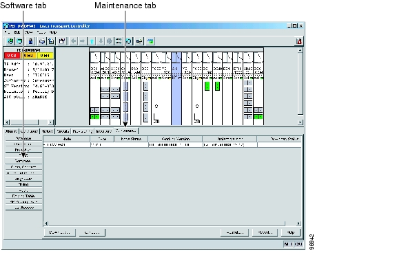
You can view the working and protect software versions that are installed on an ONS 15454 by selecting the Maintenance > Software tabs in node view ( Figure 1-5).
Figure 1-5 CTC Software Versions Found In Node View
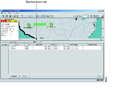
When a new CTC software version is released, use the Cisco ONS 15454 Software Upgrade Guide to upgrade the ONS 15454 software on the TCC cards. Select the Maintenance > Software tabs in network view to display the software versions installed on all the network nodes ( Figure 1-6).
Figure 1-6 CTC Software Versions Found In Network View
CTC Software Revert
When you click the Activate button after a software upgrade, the TCC copies the current working database and saves it in a reserved location in the TCC flash memory. If you later need to revert to the original working software load from the protect software load, the saved database installs automatically. You do not need to restore the database manually or recreate circuits.
Note
The revert feature is useful if a maintenance window closes while you are upgrading CTC software. You can revert to the protect software load without losing traffic. When the next maintenance window opens, complete the upgrade and activate the new software load.
Circuits created or provisioning done after a software load is activated (upgraded to a higher release) do not reinstate with a revert (for example, 4.0 to 3.4). The database configuration at the time of activation is reinstated after a revert. This does not apply to maintenance reverts (for example, 2.2.2 to 2.2.1), because maintenance releases use the same database.
CTC Operations
To use CTC in the ONS 15454, your computer must have a web browser with the correct Java Runtime Environment (JRE) installed. The correct JRE for each CTC software release is included on the Cisco ONS 15454 software CD and the ONS 15454 documentation CD. If you are running multiple CTC software releases on a network, the JRE installed on the computer must be compatible with the different software releases.
You can change the JRE version on the Preferences dialog box JRE tab. When you change the JRE version on the JRE tab, you must exit and restart CTC for the new JRE version to take effect. Table 1-6 shows JRE compatibility with ONS software releases.
Table 1-6 JRE Compatibility with ONS Software Releases
Release 2.2.1 and lower
Yes
No
No
Release 2.2.2
Yes
Yes
No
Release 3.0
Yes
Yes
No
Release 3.1
Yes
Yes
No
Release 3.2
Yes
Yes
No
Release 3.3
Yes
Yes
No
Release 3.4
No
Yes
No
Release 4.011
No
Yes
No
Release 4.1
No
Yes
No
Release 4.5
No
Yes
No
Release 4.6
No
Yes
Yes
Release 5.0
No
Yes
Yes
1 Software Releases 4.0 and higher notify you if an older version of the JRE is running on your PC or UNIX workstation.
In addition to the JRE, the Java plug-in and modified java.policy file are also included on the ONS 15454 software CD and the ONS 15454 documentation CD.
Computer Requirements
Table 1-7 lists the computer requirements for PCs and UNIX workstations to run CTC.
Table 1-7 Computer Requirements
Processor
Pentium III (or higher) 700 MHz, UltraSPARC, or equivalent
700 MHz is the recommended processor speed. You can use computers with a lower processor speed; however, you may experience longer response times and slower performance.
RAM
384 MB RAM recommended, 512 MG RAM optimum
Cisco recommends using 512 MG RAM for networks with 25 nodes or more to avoid longer response times and slower performance.
Hard Drive
20 GB recommended with 50 MB vacant space available
—
Ethernet Network Interface Converter (NIC)
10/100 BaseT
—
Operating System
•
•
—
JRE
JRE 1.4.2 or 1.3.1_02
JRE 1.4.2 is installed by the CTC Installation Wizard included on the Cisco ONS 15454 software and documentation CDs. JRE 1.4.2 provides enhancements to CTC performance, especially for large networks with numerous circuits. Cisco recommends that you use JRE 1.4.2 for networks with Software R4.6 nodes. If CTC must be launched directly from nodes running software earlier than R4.6, Cisco recommends JRE 1.3.1_02.
Web Browser
PC: Netscape 4.76, Netscape 7.x, Internet Explorer 6.x
UNIX Workstation: Netscape 4.76, Netscape 7.x
For the PC, use JRE 1.4.2 or 1.3.1_02 with any supported web browser.
For UNIX, use JRE 1.4.2 with Netscape 7.x or JRE 1.3.1_02 with Netscape 4.76.
Netscape 4.76 or 7.x is available at the following site: http://channels.netscape.com/ns/browsers/default.jsp
Internet Explorer 6.x is available at the following site: http://www.microsoft.com
java.policy File
A java.policy file modified for CTC
The java.policy file is modified by the CTC Installation Wizard included on the Cisco ONS 15454 software and documentation CDs.
Cable
User-supplied CAT-5 straight-through cable with RJ-45 connectors on each end to connect the computer to the ONS 15454 directly or through a LAN port on the TCC faceplate.
—
Modem
A compatible modem must meet the following minimum requirements:
•
•
•
•
•
•
•
—
CTC Windows
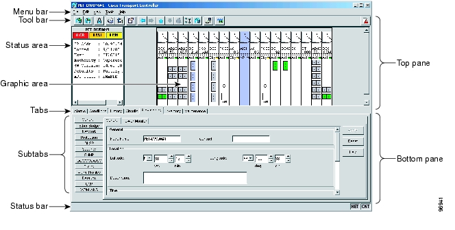
The CTC window appears after you log into an ONS 15454 ( Figure 1-7). The window includes a menu bar, toolbar, and a top and bottom pane. The top pane provides status information about the selected objects and a graphic of the current view. The bottom pane provides tabs and subtab to view ONS 15454 information and perform ONS 15454 provisioning and maintenance. From this window you can display three ONS 15454 views: network, node, and card.
Figure 1-7 Node View (Default Login View)
Node View
Node view, shown in Figure 1-7, is the first view that appears after you log into an ONS 15454. The login node is the first node shown, and it is the "home view" for the session. Node view allows you to manage one ONS 15454 node. The status area shows the node name; IP address; session boot date and time; number of Critical (CR), Major (MJ), and Minor (MN) alarms; the name of the current logged-in user; and the security level of the user; software version; and the network element default setup.
CTC Card Colors
The graphic area of the CTC window depicts the ONS 15454 shelf assembly. The colors of the cards in the graphic reflect the real-time status of the physical card and slot ( Table 1-8).
The wording on a card in node view shows the state of a card (Active, Standby, Loading, or Not Provisioned). Table 1-9 lists the card states.
Table 1-9 Node View Card States
Sty
Card is in standby
Act
Card is active
NP
Card is not present
Ldg
Card is resetting
Ports can be assigned one of four states, OOS, IS, OOS-AINS, or OOS-MT. The color of the port in both card and node view indicates the port state. Table 1-10 lists the port colors and their states.
Node View Card Shortcuts
If you move your mouse over cards in the graphic area, pop-ups display additional information about the card including the card type; the card status (active or standby); the type of alarm, such as Critical, Major, and Minor (if any); the alarm profile used by the card; and for TXP or MXP cards, the wavelength of the DWDM port. Right-click a card to reveal a shortcut menu, which you can use to open, reset, delete, or change a card. Right-click a slot to pre-provision a card (that is, provision a slot before installing the card).
Node View Tabs
Table 1-11 lists the tabs and subtabs available in the node view.
Network View
Network view allows you to view and manage ONS 15454s that have DCC connections to the node that you logged into and any login node groups you may have selected ( Figure 1-8).
Figure 1-8 Network In CTC Network View
Note
The graphic area displays a background image with colored ONS 15454 icons. A Superuser can set up the logical network view feature, which enables each user to see the same network view. The lines show DCC connections between the nodes. DCC connections can be green (active) or gray (fail). The lines can also be solid (circuits can be routed through this link) or dashed (circuits cannot be routed through this link).
There are four possible combinations for the appearance of DCCs: green/solid, green/dashed, gray/solid, and gray/dashed. DCC appearance corresponds to the following states: active/routable, active/nonroutable, failed/routable, or failed/nonroutable. Circuit provisioning uses active/routable links. Selecting a node or span in the graphic area displays information about the node and span in the status area.
The color of a node in network view, shown in Table 1-12, indicates the node alarm status.
Table 1-13 lists the tabs and subtabs available in network view.
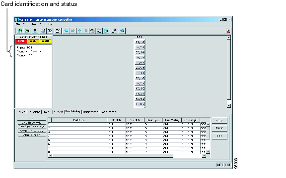
Card View
Card view provides information about individual ONS 15454 cards. Use this window to perform card-specific maintenance and provisioning ( Figure 1-9). A graphic showing the ports on the card is shown in the graphic area. The status area displays the node name, slot, number of alarms, card type, equipment type, and the card status (active or standby), card and port service states, when a card is present. The information that appears and the actions you can perform depend on the card.
Figure 1-9 CTC Card View Showing a DS1 Card
Note
Use the card view tabs and subtabs, shown in Table 1-14, to provision and manage the ONS 15454. The subtabs, fields, and information shown under each tab depend on the card type selected. The Performance tab is not available for the AIC or AIC-I cards.
Card Reset
You can reset the ONS 15454 plug-in cards by using CTC (a soft reset) or by physically reseating a card (a hard reset).
You can apply a soft reset from CTC to either an active or standby TCC2/TCC2P card without affecting traffic. A soft reset reboots the TCC2/TCC2P card and reloads the operating system and the application software. If you need to perform a hard reset on an active TCC2/TCC2P card, put the TCC2/TCC2P card into standby mode first by performing a soft reset. Additionally, a hard reset temporarily removes power from the TCC2/TCC2P card and clears all buffer memory.
Note
Network Configurations
The ONS 15454 supports a variety of network configurations, including terminal mode (TM), linear ADM, path protection, two- and four-fiber bidirectional line switched ring (BLSR), subtending rings, path protected meshed networks (PPMNs), and regenerator mode. The ONS 15454 can be combined with other Cisco ONS products or interoperate with equipment from third-parties to provide end-to-end solutions for SONET and dense wavelength division multiplexing (DWDM) networks.
New Features in Release 5.0.x
Table 1-15 lists the new hardware and software features provided in Release 5.0.x that are covered in this document.
Table 1-15 New Hardware and Software Feature
Hardware
2.5G Data Muxponder (MXP_MR_2.5G and MXPP_MR_2.5G) Cards
12-Port DS3XM-12 Transmux Card with Portless Interface Mode
48-Port DS3/EC1-48 Card
8-Port CE-100T-8 Ethernet Mapper Card with GFP, VCAT, LCAS1
96-Port Mini-BNC EIA Panels
DSX Wiring Verification Kit
Detectable Filler Card (Software support i R6.0)
Enhanced 2.5-Gb/s-10-Gb/s Muxponder-100 GHz-Tunable (MXP_2.5G_10E) Card
Enhanced 10-Gb/s Transponder-100-GHz-Tunable (TXP_MR_10E) Card
Reconfigurable OADM (ROADM) with 32-Channel Demultiplexer (32DMX) and 32-Channel Wavelength Selective Switch (32WSS) Cards
Small Form-Factor Pluggables
TCC2P Card
Universal Backplane Interface Connector - Horizontal (UBIC-H)2
UBIC-H Cable Assemblies 2.
Software
1+1 VT Protection Support
Admin SSM
Consolidated R4.7 DWDM Software
TL1-CTC Circuit Unification
Dual-Ring Interconnect for BLSR
GFP-F Support on ML-Series Ethernet Cards
Hi-Capacity RMON
In-Service Topology Upgrades
Linear Port-Mapped Ethernet Mode
Link Capacity Adjustment
Manual Provisioning of STS Around a Ring3
Open GNE
Optimized 1+1 Protection
Portless Transmux Circuits
Provisionable Patchcords
Runtime Diagnostics
SL-Series Fibre Channel Card Enhancements
State Verification Scan Before Activation
TCC2P Secure Mode Operation
VCAT Member Routing Enhancements
1 CE-100T-8 Ethernet mapper card will be available in R5.0.2.
2 Product is release independent and was introduced between R4.6 and R5.0.
3 For provisioning a STS around a ring, refer to the Cisco ONS 15454 Procedures Guide.
End of Life
Table 1-16 outlines the products which have entered the End-of-Life (EoL) process but have not reached End-of-Sale (EoS). You should analyze your spares needs in order to place an order for last time purchases. All EoL product bulletins for the ONS 15454 can be accessed at the following URL:
http://cisco.com/en/US/products/hw/optical/ps2006/prod_eol_notices_list.html
![]()
![]()
![]()
![]()
![]()
![]()
![]()
![]()
Posted: Tue Nov 27 11:03:50 PST 2007
All contents are Copyright © 1992--2007 Cisco Systems, Inc. All rights reserved.
Important Notices and Privacy Statement.