|
|

Table Of Contents
Ethernet Features and Functions
E-Series Single-card EtherSwitch
E-Series Multicard EtherSwitch Group
E-Series Port-Mapped (Linear Mapper)
E-Series Circuit Configurations
Available Circuit Sizes For E-Series Modes
Total Bandwidth Available For E-Series Modes
E-Series Q-Tagging (IEEE 802.1Q)
E-Series Priority Queuing (IEEE 802.1Q)
E-Series Spanning Tree (IEEE 802.1D)
IEEE 802.3z Flow Control and Frame Buffering
Ethernet Link Integrity Support
Gigabit EtherChannel/IEEE 802.3ad Link Aggregation
G-Series Gigabit Ethernet Transponder Mode
Enhanced State Model for Gigabit Ethernet Ports
G-Series Ethernet Circuit Configurations
Autonegotiation, Flow Control, and Frame Buffering
Ethernet Link Integrity Support
IEEE 802.1Q CoS and IP ToS Queuing
CE-100T-8 SONET Circuits and Features
CE-100T-8 Pools and STS/VT Allocation Tab
CE-100T-8 VCAT Characteristics
CE-100T-8 POS Encapsulation, Framing, and CRC
CE-100T-8 Loopback and J1 Path Trace Support
Console Port and adaptor cable
Link Aggregation (FEC, GEC, and POS)
VPN Routing/Forwarding (VRF) Lite
Accelerated Aging to Retain Connectivity
Rapid Spanning Tree (RSTP) Support
EoMPLS Configuration Guidelines
Ethernet Features and Functions
Note
The terms "Unidirectional Path Switched Ring" and "UPSR" may appear in Cisco literature. These terms do not refer to using Cisco ONS 15xxx products in a unidirectional path switched ring configuration. Rather, these terms, as well as "Path Protected Mesh Network" and "PPMN," refer generally to Cisco's path protection feature, which may be used in any topological network configuration. Cisco does not recommend using its path protection feature in any particular topological network configuration.
This chapter describes the Ethernet features and functions supported by the series of ONS 15454 Ethernet cards. By supporting Layer 1, Layer 2, and Layer 3 capabilities the various series of ONS 15454 Ethernet cards enable you to over-subscribe and efficiently pack your networks with data services, while also maintaining the flexibility to offer dedicated Ethernet Private Line (EPL) and Ethernet Private Ring (EPR) services. With ML-Series cards, efficient Ethernet transport and TDM can coexist on same card, thus enabling low cost interconnectivity for hubs and routers.
The following topics are covered in this chapter:
E-Series Overview
The E-Series cards incorporate layer 2 switching, while the CE- and G-series cards are layer 1 mapper cards. The ONS 15454 E-Series include the following Ethernet cards:
•
•
•
•
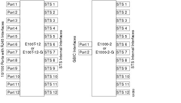
Each E100T-12 and E100T-G card has 12 front panel (user side) 10/100 Mb/s Ethernet ports and 12 STS-1 connections (622 Mb/s aggregate bandwidth to the cross-connect card) to the transport side of the network. Each of the user side Ethernet ports can be set for autosensing. Autosensing enables the ports to detect the speed of an attached Ethernet device by auto-negotiation and automatically connect at the appropriate speed and duplex mode (half or full duplex), and also determine whether to enable or disable flow control. Each E100T-12 and E100T-G card supports standards-based, wire-speed, Layer 2 Ethernet switching between its Ethernet interfaces. The IEEE 802.1Q tag logically isolates traffic (typically subscribers). IEEE 802.1Q also supports multiple classes of service.
The E1000-2 and E1000-2-G provides 2 modular GBIC (Gigabit Interface Connector) slots ports and 12 STS-1 connections to the internal interface ports on the transport side of the network. Each GBIC slot can be populated with either 1000Base-SX (short reach over multimode fiber at 850nm) or 1000Base-LX (long reach over single mode fiber at 1310nm). The slots are assigned to 12 STS-1s based internal interface transport ports. Figure 5-1 is a block diagram of the E-Series cards.
Figure 5-1 Block Diagram of E-Series Ethernet Cards
The E100T-G is the functional equivalent of the E100T-12. An ONS 15454 using XC-10G cross-connect cards requires the G versions of the E-Series Ethernet cards. The E1000-2 is the functional equivalent of the E1000-2-G. An ONS 15454 using XC-10G cross-connect cards requires the G versions (E100T-G or E1000-2-G) of the E-Series Ethernet cards.
E-Series cards support VLAN, IEEE 802.1Q, spanning tree, and IEEE 802.1D. These cards conform to the general specifications of RFC 1619, but uses Cisco's proprietary HDLC encapsulation protocol. HDLC encapsulation adds 5 overhead bytes to the payload (1 byte = flag, 1 byte = address, 1 byte = control, 1 byte = byte 1 of CRC-16, 1 byte = byte 2 of CRC-16). Because of the proprietary nature of encapsulation, E-Series Ethernet circuits have to be 'book-ended". That is, E-Series Ethernet circuits must terminate only on E-Series cards. E-Series circuits cannot terminate on G-Series cards or be handed off to an external device in its native STS format (via an optical interface).
A single ONS 15454 can support a maximum of ten Ethernet cards, which can be installed in slots 1 to 6 and 12 to 17. The ONS 15454 operates in one of three modes: single-card EtherSwitch, multi-card EtherSwitch group, or port-mapped modes for E-Series cards. Port-mapped mode is only available on systems running Release 4.0 and higher.
E-Series Single-card EtherSwitch
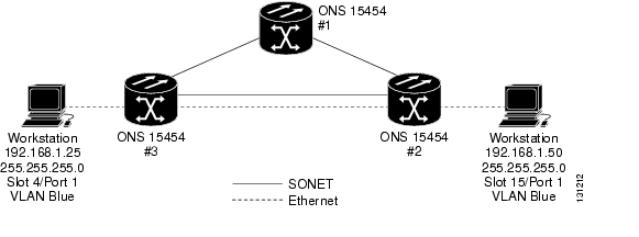
Single-card EtherSwitch allows each Ethernet card to remain a single switching entity within the ONS 15454 node. This option allows a full STS-12c worth of bandwidth between two Ethernet circuit points. Figure 5-2 illustrates a single-card EtherSwitch configuration.
Figure 5-2 Single-card EtherSwitch Operation
There is no limit on the number of single-card EtherSwitches that can be provisioned in an ONS 15454 assembly shelf, other than slot availability. All Ethernet cards installed in a node can transmit and receive to any provisioned Ethernet circuit and Virtual Local Area Network (VLAN).
Single-card EtherSwitch supports only point-to-point circuits. This allows a full STS-12c worth of bandwidth between two Ethernet circuit points, which can be divided into bandwidth increments of STS-1, STS-3c, STS-6c, or STS-12c as shown in Table 5-1.
E-Series Multicard EtherSwitch Group
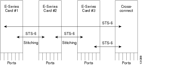
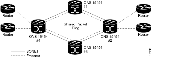
Multicard EtherSwitch group provisions two or more Ethernet cards to act as a single Layer 2 switch. It supports one STS-6c shared packet ring, two STS-3c shared packet rings, one STS-3c and three STS-1 shared packet rings, or six STS-1 shared packet rings. Half of each Ethernet card's STS bandwidth is used to "stitch" the cards together in a daisy-chain configuration (see Figure 5-3). The bandwidth of the single switch formed by the Ethernet cards matches the bandwidth of the provisioned Ethernet circuit up to STS-6c worth of bandwidth. Only one EtherGroup can be provisioned in an ONS 15454 assembly shelf. A multicard EtherSwitch group can co-exist with multiple single-card EtherSwitches in the same node. Multicard EtherSwitch group mode is required when provisioning shared packet ring circuits, but it can also be used for point-to-point circuits.
Figure 5-3 Multi-card EtherSwitch Group Operation
E-Series Port-Mapped (Linear Mapper)
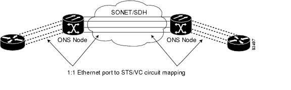
System Release 4.0 introduced the E-Series port-mapped mode, also referred to as linear mapper. Port-mapped mode configures the E-Series card to map a specific E-Series Ethernet port to one of the card's specific STS circuits (see Figure 5-4). Port-mapped mode ensures that Layer 1 transport has low latency for unicast, multicast, and mixed traffic. Ethernet and Fast Ethernet on the E100T-G or E10/100-4 card (ONS 15327) operate at line-rate speed. Gigabit Ethernet transport is limited to a maximum of 600 Mb/s because the E1000-2-G card has a maximum bandwidth of STS-12c. Ethernet frame sizes up to 1522 bytes are also supported, which allow transport of IEEE 802.1Q tagged frames. The larger maximum frame size of Q-in-Q frames (IEEE 802.1Q in IEEE 802.1Q wrapped frames) is not supported.
Figure 5-4 E-Series Mapping Ethernet Ports to STS/VC Circuits
Port-mapped mode disables Layer 2 functions supported by the E-Series in single-card and multicard mode, including STP, VLANs, and MAC address learning. It significantly reduces the service-affecting time for cross-connect and TCC card switches.
Port-mapped mode does not support VLANs in the same manner as multicard and single-card mode. The ports of E-Series cards in multicard and single-card mode can join specific VLANs. E-Series cards in port-mapped mode do not have this Layer 2 capability and only transparently transport external VLANs over the mapped connection between ports. An E-Series card in port-mapped mode does not inspect the tag of the transported VLAN, so a VLAN range of 1 through 4096 can be transported in port-mapped mode.
Port-mapped mode does not perform any inspection or validation of the Ethernet frame header. The Ethernet CRC is validated, and any frame with an invalid Ethernet CRC is discarded.
E-Series cards provisioned in port-mapped mode can terminate multiple point-to-point circuits per card, with each circuit terminating on a separate Ethernet port. The Ethernet circuits created in port-mapped mode can be protected via path protection, 2-Fiber and 4-Fiber BLSR, as well as linear APS. The supported circuit sizes are identical to the current single-card EtherSwitch applications. Ethernet circuits can traverse any ONS 15454 SONET network as long as they are terminated on another E-Series card provisioned in port-mapped mode.
Port-mapped mode also allows the creation of STS circuits between any two E-Series cards, including the E100T-G, E1000-2-G, and the E10/100-4 card on the ONS 15327. Port-mapped mode does not allow ONS 15454 E-Series cards to connect to the ML-Series or G-Series cards, but does allow an ONS 15327 E10/100-4 card provisioned with LEX encapsulation to connect to the ML-Series card.
The benefit of the port-mapped mode, is that it allows Ethernet traffic to be mapped directly onto the SONET circuit without passing through a Layer 2 switching engine. Although the Layer 2 switching capabilities of E-Series cards provide a much wider range of functionality than a simple Layer 1 Ethernet-to-SONET mapping scheme, there are several characteristics unique to the E-Series card's Layer 2 switching engine that may present limitations in some applications. Such limitations of the Layer 2 switching engine on the E-Series card include:
•
•
•
When you place the E-Series card in port-mapped mode, you can realize the following benefits:
•
•
•
•
E-Series Circuit Configurations
Ethernet circuits can link ONS 15454 nodes through point-to-point, shared packet ring, or hub and spoke configurations. Two nodes usually connect with a point-to-point configuration. More than two nodes usually connect with a shared packet ring configuration or a hub and spoke configuration. Ethernet manual cross-connects allow you to cross connect individual Ethernet circuits to an STS channel on the ONS 15454 optical interface and also to bridge non-ONS SONET network segments.
E-Series Point-to-Point Ethernet Circuits
The ONS 15454 can set up a point-to-point Ethernet circuit as Single-card EtherSwitch, Multi-card EtherSwitch Group, or Port-mapped. Multi-card EtherSwitch Group mode limits bandwidth to STS-6c of bandwidth between two Ethernet circuit points, but allows adding nodes and cards and making a shared packet ring. Single-card EtherSwitch and port-mapped modes allows a full STS-12c of bandwidth between two Ethernet circuit points. These circuit configurations are illustrated in the following figures:
Figure 5-5 Multicard EtherSwitch Point-to-Point Circuit
Figure 5-6 Single-card EtherSwitch Point-to-Point Circuit
Figure 5-7 Port-mapped Point-to-Point Circuit
E-Series Shared Packet Ring Ethernet Circuits
A shared packet ring allows additional nodes (besides the source and destination nodes) access to an Ethernet STS circuit. The E-Series card ports on the additional nodes can share the circuit's VLAN and bandwidth. Figure 5-8 illustrates a shared packet ring.
Figure 5-8 Shared Packet Ring Ethernet Circuit
E-Series Hub-and-Spoke Ethernet Circuits
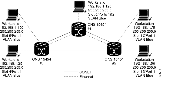
The hub-and-spoke configuration connects point-to-point circuits (the spokes) to an aggregation point (the hub). In many cases, the hub links to a high-speed connection and the spokes are Ethernet cards. Figure 5-9 illustrates a sample hub-and- spoke ring.
Figure 5-9 Hub and Spoke Ethernet Circuit
E-Series Ethernet Manual Cross-Connects
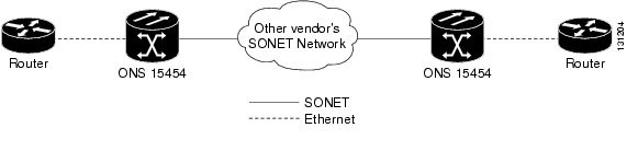
ONS 15454 nodes require end-to-end CTC visibility between nodes for normal provisioning of Ethernet circuits. When other vendors' equipment sits between ONS 15454 nodes, as shown in Figure 5-10, OSI/TARP- based equipment does not allow tunneling of the ONS 15454 TCP/IP-based DCC. To circumvent this lack of continuous DCC, the Ethernet circuit must be manually cross connected to an STS channel riding through the other vendors' network. This allows an Ethernet circuit to run from ONS 15454 node to ONS 15454 node utilizing the other vendors' network.
Figure 5-10 Ethernet Manual Cross-Connects
Available Circuit Sizes For E-Series Modes
Table 5-2 shows the circuit sizes available for E-Series modes on the ONS 15454.
Table 5-2 ONS 15454 E-Series Ethernet Circuit Sizes
Port-Mapped and Single-Card EtherSwitch
STS-1
STS-3c
STS-6c
STS-12c
Multicard EtherSwitch
STS-1
STS3c
STS-6c
Total Bandwidth Available For E-Series Modes
Table 5-3 shows the total bandwidth available for E-Series modes on the ONS 15454.
Table 5-3 E-Series Total Bandwidth Available
Port-Mapped and Single-Card EtherSwitch
STS-12c
Multicard EtherSwitch
STS-6c
E-Series Circuit Protection
Different combinations of E-Series circuit configurations and SONET network topologies offer different levels of E-Series circuit protection. Table 5-4 details the available protection.
E-Series Frame Processing
For all frames, an IEEE 802.3-formatted frame enters the ingress interface on the E-Series Ethernet cards. The 8-byte Ethernet preamble is stripped and the remaining frame is buffered on the card while being processed. The frame check sequence (FCS) for the frame is computed as required by the 802.3 standard. If the frame is in error, (i.e. the computed FCS does not match the embedded FCS), the frame is discarded. Higher layer protocols are responsible for retransmission when traffic is dropped.
For frames on tagged ports, if the frame has entered via a port configured as "Tagged," the Ethernet card reads the contents of the Tag Control Indicator (TCI) field and determines whether the VLAN tag matches the list of configured VLANs that are eligible for ingress on that port. If the frame is not "eligible" it is dropped (in this scenario, the "dropped-frames" counter does not increment). Based on the priority setting in the TCI field, the frame is queued for further processing.
For frames on untagged ports, if the ingress port has been configured as "Untagged," a tag corresponding to the assigned VLAN for that port is inserted into the TCI field. The addition of 802.1q tagging adds 4 bytes to the previously untagged frame. All Tagged frames will be dropped. However, if a Tagged frame with the same VLAN ID as that assigned to the port enters the port, it will pass through and will not be dropped. At the egress port the 802.1Q/p header is stripped from the frame.
Note
For frames on Untagged ports, the provisioned priority setting for the Untagged port is also inserted in the TCI field and the frame is queued for further processing based on that priority. At the egress port, the priority is removed along with the TCI field.
For all frames, the source MAC address is read and checked against the MAC forwarding table. If a frame from this source has not been received previously, a new entry is made in the table with the MAC address, the VLAN associated with it, and the slot/port/STS it was received on. The destination MAC address is checked against the MAC forwarding table. If the destination MAC address is not present in the table, the Ethernet cards will broadcast to its connected neighbors on the same VLAN to determine the appropriate egress port or STS. If the destination is known, the frame is switched to the appropriate destination slot, port, or STS. Once the destination has been determined, the entire Ethernet frame is inserted into a High-level Data Link Control (HDLC) frame. This adds 5 bytes of overhead to the payload (1 byte = flag, 1 byte = address, 1 byte = control, 1 byte =byte 1 of CRC-16, 1 byte = byte 2 of CRC-16). The newly formatted frame leaves the Ethernet card and is inserted into the appropriate STS payload.
For all frames being switched to an STS payload, the Ethernet card inserts a value of 0001 in the C2 byte of the SONET Path Overhead indicating that the contents of the STS SPE contains "Equipped - non-specific payload". The purpose of this is to allow for first level verification by confirming that both ends of the path are using the same SPE content and protocol.
E-Series Frame Length
The ONS 15454 E-Series cards can support 1522-byte frames on Tagged ports. On Untagged ports the E-Series can support frames up to 1518 bytes. Frames greater than 1522 bytes will be dropped for both the Tagged and Untagged ports.
MPLS and VLAN Trunking (also referred to as Q-in-Q) require frame lengths exceeding 1522 bytes. The E-Series cards cannot support these protocols. However, a workaround is possible using an externally connected device.
Large frame support makes it possible to provide MPLS Ethernet. However, many Ethernet switches, including the existing E-Series cards, do not support large frames, thus forcing routers to compensate as a workaround. The router that needs to put an over-sized MPLS frame onto an Ethernet interface must fragment the data and adjust for an MTU of 1500 bytes. However, some IP packets may be marked as do-not-fragment (DF bit), which should trigger MTU negotiation via ICMP. If the initiating host doesn't support MTU discovery, the DF bit can be cleared on the Cisco device and force fragmentation. However, fragmentation may hurt routing performance, particularly on a core device.
E-Series Buffer Size
E-Series cards have a distributed, shared memory architecture. So the aggregate buffer memory applies to all ports and STSs on the card. The E100T-12-G has 32 Mb of physical buffer memory. Of this, 8 Mb is addressable for forwarding frames. The E1000-2-G has 24 Mb of physical memory, with 6 Mb that is addressable.
IEEE 802.3z Flow Control
The E100T-G or E10/100-4 (operating in any mode) and the E1000-2-G (operating port-mapped mode) support IEEE 802.3z symmetrical flow control and propose symmetric flow control when autonegotiating with attached Ethernet devices. For flow control to operate, both the E-Series port and the attached Ethernet device must be set to autonegotiation (AUTO) mode. The attached Ethernet device might also need to have flow control enabled. The flow-control mechanism allows the E-Series to respond to pause frames sent from external devices and send pause frames to external devices.
For the E100T-G or E10/100-4 (operating in any mode) and the E1000-2-G (operating port- mapped mode), flow control matches the sending and receiving device throughput to that of the bandwidth of the STS circuit. For example, a router might transmit to the Gigabit Ethernet port on the E-Series in port-mapped mode. The data rate transmitted by the router might occasionally exceed 622 Mbps, but the ONS 15454 circuit assigned to the E-Series port in port-mapped mode is a maximum of STS-12c (622.08 Mbps). In this scenario, the ONS 15454 sends out a pause frame and requests that the router delay its transmission for a certain period of time.
IEEE 802.3z flow control and frame buffering to reduces data traffic congestion. Approximately 8MB on the E100T-12-G and 6MB on the E1000-2-G of total buffer memory is available for the transmit and receive channels to buffer over-subscription. When the Ethernet connected device nears capacity, it will issue an 802.3z flow control frame called a "pause frame" which instructs the E-Series card to stop sending packets for a specific period of time.
E-Series Ethernet cards will only respond to 802.3z "pause frames" connected to 802.3z compliant stations. E-Series Ethernet cards will not issue 802.3z "pause frames" to end stations.
Note
EtherChannel
E-Series cards do not support fast or Gigabit EtherChannel.
E-Series Rate-Limiting
For E-Series Ethernet cards, you can specify a value of exactly 10 Mb/s, 100 Mb/s or 1000 Mb/s per port on the user-interface side or STS-1, STS-3c, STS-6c or STS-12c on the optical transport side. If the STS-N circuit is shared by multiple ONS 15454 nodes, the bandwidth per node cannot be limited. Also, if multiple ports on the same node share the STS-N, the bandwidth per port cannot be limited.
There are work-around solutions available to limit the amount of bandwidth allocated to a port. For example, if you need Ethernet rate shaping, Cisco can provide a solution using a switch such as the Cisco Catalyst 3550.
E-Series Latency
Store-and-forward latency is the time delay between the Last-bit-In and the First-bit-Out (LIFO). The LIFO latency of an E-Series card depends on the offered packet size and ranges from 10 to 55 microseconds (ms). Average LIFO latency through an E-Series card between local Ethernet ports is as follows:
Table 5-5 Average Latency
64
10
128
10
256
14
512
22
1024
36
1280
47
1518
55
The latency to switch frames between front-side Ethernet ports versus back-end STS circuit connections is equivalent. However, when measuring end-to-end Ethernet latency across the SONET network, the delay will include the time for the E-Series switching, cross-connection, and the OC-N line card for each side of the connection, as well as the propagation delay through the fiber. The data above only characterizes latency of the E-Series card itself.
E-Series VLAN Support
You can provision up to 509 VLANs. Specific sets of ports define the broadcast domain for the ONS 15454. The definition of VLAN ports includes all Ethernet and packet-switched SONET port types. All VLAN IP address discovery, flooding, and forwarding is limited to these ports.
The IEEE 802.1Q-based VLAN mechanism provides logical isolation of subscriber LAN traffic over a common SONET transport infrastructure. Each subscriber has an Ethernet port at each site, and each subscriber is assigned to a VLAN. Although the subscriber's VLAN data flows over shared circuits, the service appears to the subscriber as a private data transport.
Note
The number of VLANs used by circuits and the total number of VLANs available for use appears in CTC on the VLAN counter as shown in Figure 5-11.
Figure 5-11 Edit Circuit Dialog Box Listing Available VLANs
E-Series Q-Tagging (IEEE 802.1Q)
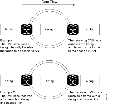
IEEE 802.1Q allows the same physical port to host multiple 802.1Q VLANs. Each 802.1Q VLAN represents a different logical network. The E-Series cards work with external Ethernet devices that support IEEE 802.1Q and those that do not support IEEE 802.1Q. If a device attached to an E-Series Ethernet port does not support IEEE 802.1Q, the ONS 15454 only uses Q-tags internally. The ONS 15454 associates these Q-tags with specific ports.
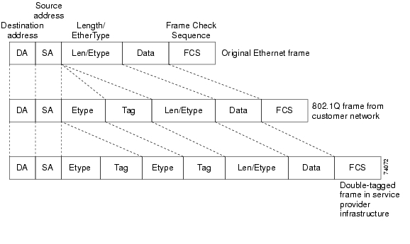
With Ethernet devices that do not support IEEE 802.1Q, the ONS 15454 node takes non-tagged Ethernet frames that enter the ONS 15454 network and uses a Q-tag to assign the packet to the VLAN associated with the network's ingress port. The receiving ONS 15454 node removes the Q-tag when the frame leaves the ONS 15454 network (to prevent older Ethernet equipment from incorrectly identifying the 8021.Q packet as an illegal frame). The ingress and egress ports on the E-Series Ethernet cards must be set to Untag for this process to occur. Untag is the default setting for ONS 15454 Ethernet ports. Example #1 in Figure 5-12 illustrates Q-tag use only within an ONS 15454 Ethernet network.
With Ethernet devices that support IEEE 802.1Q, the ONS 15454 uses the Q-tag attached by the external Ethernet devices. Packets enter the ONS 15454 network with an existing Q-tag; the ONS 15454 node uses this same Q-tag to forward the packet within the ONS 15454 network and leaves the Q-tag attached when the packet leaves the ONS 15454 network. Set both entry and egress ports on the E-Series Ethernet cards to Tagged for this process to occur. Example #2 in Figure 5-12 illustrates the handling of packets that both enter and exit the ONS 15454 network with a Q-tag.
Figure 5-12 Q-tag Moving Through a VLAN
E-Series Priority Queuing (IEEE 802.1Q)
Note
Networks without priority queuing handle all packets on a first-in-first-out basis. Priority queuing reduces the impact of network congestion by mapping Ethernet traffic to different priority levels. The ONS 15454 supports priority queuing. The ONS 15454 takes the eight priorities specified in IEEE 802.1Q and maps them to two queues shown in Table 5-6. Q-tags carry priority queuing information through the network.
Table 5-6 Priority Queuing
0, 1, 2, 3
Low
30%
4, 5, 6, 7
High
70%
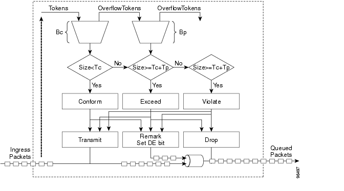
The ONS 15454 uses a "leaky bucket" algorithm to establish a weighted priority (not a strict priority). A weighted priority gives high-priority packets greater access to bandwidth, but does not totally preempt low-priority packets. During periods of network congestion, roughly 70% of bandwidth goes to the high-priority queue and the remaining 30% goes to the low-priority queue. A network that is too congested will drop packets. Figure 5-13 illustrates the priority queuing process.
Figure 5-13 Priority Queuing Process
E-Series Spanning Tree (IEEE 802.1D)
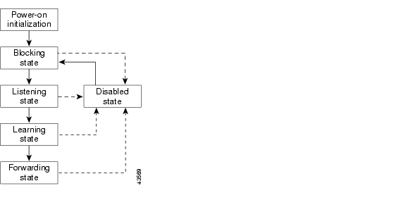
The Cisco ONS 15454 operates spanning tree protocol (STP) according to IEEE 802.1D when an E-Series Ethernet card is installed. The spanning tree algorithm places each Ethernet port into either a forwarding state or blocking state. All the ports in the forwarding state are considered to be in the current spanning tree. The collective set of forwarding ports creates a single path over which frames are sent. E-Series cards can forward frames out ports and receive frames in ports that are in forwarding state. E-Series cards do not forward frames out ports and receive frames in ports that are in a blocking state.
STP operates over all packet-switched ports including Ethernet and OC-N ports. On Ethernet ports, STP is enabled by default but may be disabled with CTC by placing a check in the box under the Provisioning > Ether Port tabs at the card-level view. You can also disable or enable spanning tree on a circuit-by-circuit basis on unstitched E-Series Ethernet cards in a point-to-point configuration. However, turning off spanning tree protection on a circuit-by-circuit basis means that the ONS 15454 system is not protecting the Ethernet traffic on this circuit, and the Ethernet traffic must be protected by another mechanism in the Ethernet network. On OC-N interface ports, STP activates by default and cannot be disabled.
You can enable STP on the Ethernet ports to allow redundant paths to external Ethernet equipment. STP spans the ONS 15454 multi-service cards so that both equipment and facilities are protected against failure.
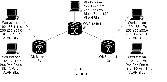
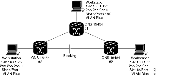
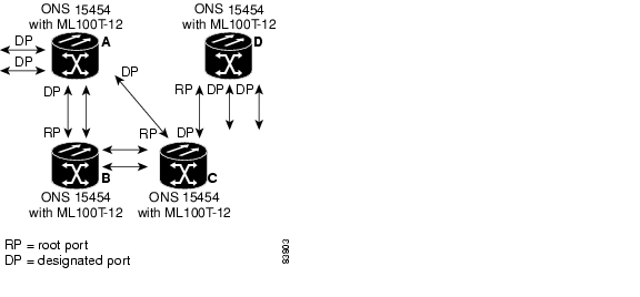
STP detects and eliminates network loops. When STP detects multiple paths between any two network hosts, STP blocks ports until only one path exists between any two network hosts as shown in Figure 5-14. The single path eliminates possible bridge loops. This is crucial for shared packet rings, which naturally include a loop.
Figure 5-14 ONS 15454 Network with STP
Now when the Workstation connected to ONS 15454 #1 sends a frame to the Workstation connected to ONS 15454 #3, the frame does not loop. ONS 15454 #1 sends a copy to ONS 15454 #3, but ONS 15454 #3 cannot forward it to ONS 15454 #2 out its Ethernet port because it is blocking.
To remove loops, STP defines a tree that spans all the switches in an extended network. STP forces certain redundant data paths into a standby (blocked) state. If one network segment in the STP becomes unreachable, the STP algorithm reconfigures the STP topology and reactivates the blocked path to reestablish the link. STP operation is transparent to end stations, which do not discriminate between connections to a single LAN segment or to a switched LAN with multiple segments.
The ONS 15454 supports one STP instance per circuit and a maximum of eight STP instances per ONS node.
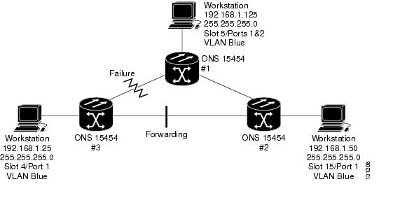
If the link between ONS 15454 #1 and ONS 15454 #3 fails, STP would reconverge so that ONS 15454 #3 would no longer block. For example, in Figure 5-15, that link has failed and STP has changed. Typically STP takes about 30-50 seconds to reconverge. However, since the ONS 15454 has SONET protection, the physical layer reroutes in less than 50 ms and STP does not have to reconverge. The links that are blocked by STP are unused, until a topology (physical connectivity) change.
Figure 5-15 ONS 15454 Network with STP After Link Failure
The Circuit window shows forwarding spans and blocked spans on the spanning tree map ( Figure 5-16).
Figure 5-16 Spanning Tree Map on Circuit Window
Note
Caution
Note
E-Series Multi-Instance Spanning Tree and VLANs
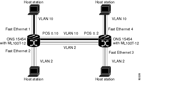
The ONS 15454 can operate multiple instances of STP to support VLANs in a looped topology. The ONS 15454 supports one STP instance per circuit and a maximum of eight STP instances per ONS 15454. You can dedicate separate circuits across the SONET ring for different VLAN groups (i.e., one for private TLS services and one for Internet access). Each circuit runs its own STP to maintain VLAN connectivity in a multi-ring environment.
Spanning Tree on a Circuit-by-Circuit Basis
You can also disable or enable spanning tree on a circuit-by-circuit basis on unstitched Ethernet cards in a point-to-point configuration. This feature allows customers to mix spanning tree protected circuits with unprotected circuits on the same card. It also allows two single-card EtherSwitch Ethernet cards on the same node to form an intranode circuit.
E-Series Spanning Tree Parameters
Default spanning tree parameters listed in Table 5-7 are appropriate for most situations, but can be modified as required.
E-Series Utilization Formula
Line utilization is calculated with the following formula:
((inOctets + outOctets) + (inPkts + outPkts) * 20)) * 8 / 100% interval * maxBaseRate * 2.
The interval is defined in seconds. maxBaseRate is defined by raw bits/second in one direction for the Ethernet port (i.e. 1 Gb/s). maxBaseRate is multiplied by 2 in the denominator to determine the raw bit rate in both directions. Table 5-8 lists the maximum Bit rate by circuit size.
Table 5-8 maxRate for STS Circuits
STS-1
51840000 bps
STS-3c
155000000 bps
STS-6C
311000000 bps
STS-12c
622000000 bps
MAC Forwarding Table
A MAC address is a hardware address that physically identifies a network device. The ONS 15454 MAC forwarding table, will allow you to see all the MAC addresses attached to the enabled ports of an E-Series Ethernet card or an E-Series Ethernet Group. This includes the MAC address of the network device attached directly to the Ethernet port and any MAC addresses on the ONS 15454 network linked to the port. The MAC addresses table lists the MAC addresses stored by the ONS 15454 and the VLAN, Slot/Port/STS, and circuit that links the ONS 15454 to each MAC address.
Hash Table
Hashing is an algorithm for organizing the MAC forwarding table. In the E-Series cards, the hash table consists of approximately 1500 "buckets" with capacity for 5 MAC address entries in each bucket. The hash algorithm reduces a MAC address to smaller pseudo-random index values used to streamline lookup performance. In this scenario, MAC addresses that equate to the same hash value, post the first five learned entries for that index bucket, may not be included in the forwarding table; and therefore may not be recognized. Frames destined for unknown MAC addresses are flooded. Hashing is common practice and will most likely not be an issue in your applications, since proliferated MAC addresses are fairly random.
G-Series Overview
The G-Series Ethernet cards support high bandwidth, low latency, point-to-point Gigabit Ethernet connectivity. Each interface will negotiate for full-duplex operation and 802.3z flow control (asymmetric) with a maximum bandwidth of 1 Gb/s (2 Gb/s bidirectional) per port up to 2.5 Gb/s (5 Gb/s bidirectional) per card. The ONS 15454 G-Series include the following Ethernet cards:
•
•
The G1000-4 card supports bandwidth guarantees on a per port basis through the provisioning of SONET STS-based circuits between card ports. You can map the four ports on the G1000-4 independently to any combination of STS-1, STS-3c, STS-6c, STS-9c, STS-12c, STS-24c, and STS-48c circuit sizes, provided the sum of the circuit sizes that terminate on a card do not exceed STS-48c.
The G-Series cards provide up to 4 circuits and offer multiple protection capabilities, depending upon the users needs. The transported Gigabit Ethernet (GE) circuits can be protected using SONET switching, path protection, BLSR, or PPMN; offering sub 50 ms restoration in the event of a transport network outage. The "client" card interface may be protected by leveraging Gigabit EtherChannel or link aggregation protocols. This allows you to provision two or more circuits between terminal devices, allowing these circuits to be routed over multiple G-Series cards. The GE circuits can also be operated over unprotected OC-N spans.
The G1K-4 card is a high density GE card. It provides four GBIC interfaces, and supports ethernet frames up to 10,000 bytes. The G1K-4 card operates identically to the G1000-4 card, except the new card will interoperate with the XC or XC-VT cross-connect cards, when installed in the high-speed multi-service I/O slots (5, 6, 12, and 13). Both, the G1K-4 and G1000-4 cards can be installed in any multipurpose I/O slot when interoperating with the XC-10G cross-connect card. These constraints do not apply to a G-Series card configured for Gigabit Ethernet Transponder Mode. The G1K-4 card is backward compatible to System Release 3.2 software.
Software R4.0 and later identifies G1K-4 cards at physical installation. Software R3.4 and earlier identifies both G1000-4 and G1K-4 cards as G1000-4 cards at physical installation.
The following GBIC modules are available as separate orderable products:
•
•
•
The 850nm SX optics are designed for multi-mode fiber and distances of up to 220 meters on 62.5micron fiber and up to 550 meters on 50 micron fiber. The 1300nm LX optics are designed for single mode fiber and distances of up to 5 kilometers. The 1550nm very long reach ZX optics are designed for a distances of up to 70 kilometers.
G-Series Ethernet Example
Figure 5-17 shows an example of a G-Series Ethernet application. In this example, data traffic from the GE port of a high-end router travels across the ONS 15454 point-to-point circuit to the GE port of another high-end router.
Figure 5-17 Data Traffic Using a G1000-4 Point-to-Point Circuit
The G-Series cards can carry over a SONET network any Layer 3 protocol that can be encapsulated and transported over Gigabit Ethernet, such as IP or IPX. The data is transmitted on the GE fiber into a standard Cisco GBIC on a G1000-4 or G1K-4 card. These Ethernet cards transparently map Ethernet frames into the SONET payload by multiplexing the payload onto a SONET OC-N card. When the SONET payload reaches the destination node, the process is reversed and the data is transmitted from a standard Cisco GBIC in the destination G-Series card onto the GE fiber.
The G-Series cards discard certain types of erroneous Ethernet frames rather than transport them over SONET. Erroneous Ethernet frames include corrupted frames with CRC errors and under-sized frames that do not conform to the minimum 64-byte length Ethernet standard. The G-Series cards forward valid frames unmodified over the SONET network. Information in the headers is not affected by the encapsulation and transport. For example, packets with formats that include IEEE 802.1Q information will travel through the process unaffected.
IEEE 802.3z Flow Control and Frame Buffering
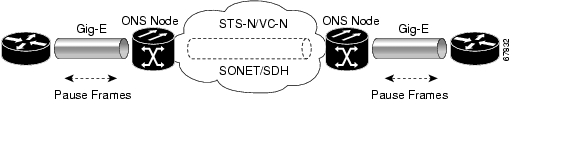
The G-Series Ethernet cards supports IEEE 802.3z flow control and frame buffering to reduce data traffic congestion. To buffer over-subscription, 512 KB of buffer memory is available for the receive and transmit channels on each port. When the buffer memory on the Ethernet port nears capacity, the ONS 15454 uses IEEE 802.3z flow control to send back a pause frame to the source at the opposite end of the Gigabit Ethernet connection.
The pause frame instructs that source to stop sending packets for a specific period of time. The sending station waits the requested time before sending more data. Figure 5-17 illustrates pause frames being sent from the ONS 15454s to the sources of the data.
The G-Series cards have symmetric flow control. Symmetric flow control allows the G-Series cards to respond to pause frames sent from external devices and to send pause frames to external devices. Prior to Software R4.0, flow control on the G-Series cards was asymmetric, meaning that the cards sent pause frames and discarded received pause frames.
Software Release 5.0 and later features separate CTC provisioning of autonegotiation and flow control. A failed autonegotiation results in a link down.
When both autonegotiation and flow control are enabled, the G-Series card proposes symmetrical flow control to the attached Ethernet device. Flow control may be used or not depending on the result of the autonegotiation.
If autonegotiation is enabled but flow control is disabled, then the G-Series proposes no flow control during the autonegotiation. This negotiation succeeds only if the attached device agrees to no flow control.
If autonegotiation is disabled, then the attached device's provisioning is ignored. The G-Series card's flow control is enabled or disabled based solely on the G-Series card's provisioning.
This flow-control mechanism matches the sending and receiving device throughput to that of the bandwidth of the STS circuit. For example, a router may transmit to the GE port on the G1000-4. This particular data rate may occasionally exceed 622 Mb/s, but the ONS 15454 circuit assigned to the G1000-4 port may be only STS-12c (622.08 Mb/s). In this example, the ONS 15454 sends out a pause frame and requests that the router delay its transmission for a certain period of time. With a flow control capability combined with the substantial per-port buffering capability, a private line service provisioned at less than full line rate capacity (STS-24c) is nevertheless very efficient because frame loss can be controlled to a large extent.
The G-Series cards have flow control threshold provisioning, which allows you to select one of three watermark (buffer size) settings: default, low latency, or custom. Default is the best setting for general use and was the only setting available prior to Software R4.1. Low latency is good for sub-rate applications, such as voice-over-IP (VoIP) over an STS-1. For attached devices with insufficient buffering, best effort traffic, or long access line lengths, set the G-Series to a higher latency.
The custom setting allows you to specify an exact buffer size threshold for Flow Ctrl Lo and Flow Ctrl Hi. The flow control high setting is the watermark for sending the Pause On frame to the attached Ethernet device; this frame signals the device to temporarily stop transmitting. The flow control low setting is the watermark for sending the Pause Off frame, which signals the device to resume transmitting. With a G-Series card, you can only enable flow control on a port if autonegotiation is enabled on the device attached to that port.
External Ethernet devices with autonegotiation configured to interoperate with G-Series cards running releases prior to Software R4.0 do not need to change autonegotiation settings when interoperating with G-Series cards running Software R4.0 and later.
Some important characteristics of the flow control feature on the G1000-4 include:
•
•
•
Ethernet Link Integrity Support
The G-Series cards support end-to-end Ethernet link integrity. This capability is integral to providing an Ethernet private line service and correct operation of Layer 2 and Layer 3 protocols on the external Ethernet devices attached at each end. End-to-end Ethernet link integrity essentially means that if any part of the end-to-end path fails the entire path fails. Failure of the entire path is ensured by turning off the transmit lasers at each end of the path. The attached Ethernet devices recognize the disabled transmit laser as a loss of carrier and consequently an inactive link.
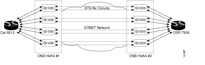
As shown in Figure 5-18, a failure at any point of the path causes the G1000-4 card at each end to disable its Tx transmit laser at their ends, which causes the devices at both ends to detect link down. If one of the Ethernet ports is administratively disabled or set in loopback mode, the port is considered a "failure" for the purposes of end-to-end link integrity because the end-to-end Ethernet path is unavailable. The port "failure" also cause both ends of the path to be disabled. The G1K-4 operates in the same manner.
Figure 5-18 End-to-End Ethernet Link Integrity Support
Note
Note
Gigabit EtherChannel/IEEE 802.3ad Link Aggregation
The end-to-end Ethernet link integrity feature of G-Series cards can be used in combination with Gigabit EtherChannel capability on attached devices. The combination provide an Ethernet traffic restoration scheme that has a faster response time than alternate techniques such as spanning tree re-routing, yet is more bandwidth efficient because spare bandwidth does not need to be reserved.
G-Series Ethernet cards supports all forms of Link Aggregation technologies including Gigabit EtherChannel (GEC) which is a Cisco proprietary standard as well as the IEEE 802.3ad standard. The end-to-end link integrity feature of the G-Series cards allows a circuit to emulate an Ethernet link. This allows all flavors of Layer 2 and Layer 3 re-routing, as well as technologies such as link aggregation, to work correctly with the G-Series cards. The G-Series cards support Gigabit EtherChannel (GEC), which is a Cisco proprietary standard similar to the IEEE link aggregation standard (IEEE 802.3ad). Figure 5-19 illustrates G-Series GEC support.
Figure 5-19 G-Series Gigabit EtherChannel (GEC) Support
Although G-Series cards do not actively run GEC, they do supports the end-to-end GEC functionality of attached Ethernet devices. If two Ethernet devices running GEC connect through G-Series cards to an ONS 15454 network, the ONS 15454 SONET side network is transparent to the EtherChannel devices. The EtherChannel devices operate as if they are directly connected to each other. Any combination of GE parallel circuit sizes can be used to support GEC throughput.
GEC provides line-level active redundancy and protection (1:1) for attached Ethernet equipment. It can also bundle parallel GE data links together to provide more aggregated bandwidth. STP operates as if the bundled links are one link and permits GEC to utilize these multiple parallel paths. Without GEC, STP only permits a single non-blocked path. GEC can also provide G-Series card-level protection or redundancy because it can support a group of ports on different cards (or different nodes) so that if one port or card has a failure, then traffic is re-routed over the other port or card.
The end-to-end Ethernet link integrity feature can be used in combination with GEC capability on attached devices. The combination provides an Ethernet traffic restoration scheme that has a faster response time than alternate techniques such as spanning tree rerouting, yet is more bandwidth efficient because spare bandwidth does not need to be reserved.
G-Series Gigabit Ethernet Transponder Mode
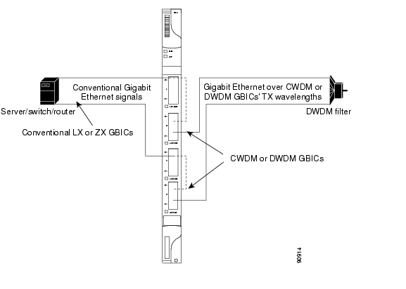
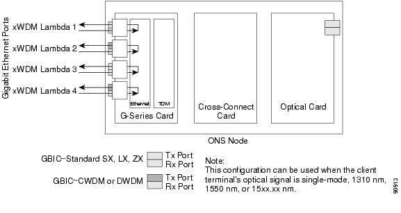
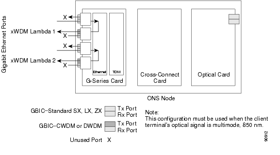
Starting with Software Release 4.1, the G-Series card can be configured as a transponder. Transponder mode can be used with any G-Series supported GBIC (SX, LX, Zx, CWDM, or DWDM). Figure 5-20 shows a card level overview of a transponder mode application.
Figure 5-20 Card Level Overview of G-Series One-Port Transponder Mode Application
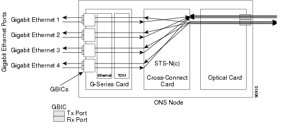
A G-Series card configured as a transponder operates quite differently than a G-Series card configured for SONET. In SONET configuration, the G-Series card receives and transmits Gigabit Ethernet traffic out the Ethernet ports and GBICs on the front of the card. This Ethernet traffic is multiplexed on and off the SONET network through the cross-connect card and the OC-N card (see Figure 5-21).
Figure 5-21 G-Series in Default SONET Mode
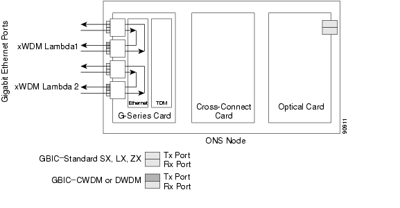
In transponding mode, the G-Series Ethernet traffic never comes into contact with the cross-connect card or the SONET network, it stays internal to the G-Series card and is routed back to a GBIC on that card (see Figure 5-22).
Figure 5-22 G-Series Card in Transponder Mode (Two-Port Bidirectional)
A G-Series card can either be configured for transponding mode or as the SONET default. When any port is provisioned in transponding mode, the card is in transponding mode and no SONET circuits can be configured until every port on the card goes back to SONET mode. Refer to the Cisco ONS 15454 Procedure Guide for detailed instructions on how to provision G-Series ports for transponder mode.
All SONET circuits must be deleted before a G-Series card can be configured in transponding mode. An ONS 15454 can host the card in any or all of the twelve traffic slots on the ONS 15454 and supports a maximum of 24 bidirectional or 48 unidirectional lambdas.
A G-Series card configured as a transponder can be in one of three modes:
•
•
•
Two-Port Bidirectional Transponder
Two-port bidirectional transponder mode maps the transmitted and received Ethernet frames of one G-Series card port into the transmit and receive of another port (see Figure 5-22). Transponder bidirectional port mapping can be any port to any port on the same card.
One-Port Bidirectional Transponder
One-port bidirectional transponder mode shown in Figure 5-23 maps the Ethernet frames received at a port out the transmitter of the same GBIC. This mode is similar to two-port bidirectional transponder mode except that a receive port is mapped only to the transmit port on the same GBIC. Although the data path of the one-port bidirectional transponder mode is identical to that of a facility loopback. The transponding mode is not a maintenance mode and does not suppress non-SONET alarms, like loss of carrier (CARLOSS).
This mode can be used for intermediate DWDM signal regeneration and to take advantage of the wide band capability of the CWDM and DWDM GBICs, which allows you to receive on multiple wavelengths but transmit on a fixed wavelength.
Figure 5-23 One-Port Bidirectional Transponding Mode
Two-Port Unidirectional Transponder
Ethernet frames received at one port's receiver will be transmitted out the transmitter of another port. This mode is similar to two-port bidirectional transponder mode except only one direction is used ( Figure 5-24). One port has to be provisioned as unidirectional transmit only and the other port as unidirectional receive. The port configured as unidirectional transmit ignores any lack of signal on the receive port, so the receive port fiber does not need not be connected. The port configured as unidirectional receive does not turn on the transmit laser, and so the transmit port fiber does not need to be connected.
This mode can be used when only one direction needs to be transmitted over CWDM/DWDM, for example certain VOD applications.
Figure 5-24 Two-Port Unidirectional Transponder
The operation of a G-Series card in transponder mode differs from a G-Series card in SONET mode in the following ways:
•
•
•
•
•
•
•
•
•
Note
The operation of a G-Series card in transponder mode is also similar to the operation of a G-Series card in SONET mode as follows:
•
•
•
•
•
Enhanced State Model for Gigabit Ethernet Ports
For Release 5.0 and higher, the G-Series supports the Enhanced State Model (ESM) for the Gigabit Ethernet ports, as well as for the SONET circuit.
The Gigabit Ethernet ports can be set to the ESM service states including the automatic in-service administrative state (IS, AINS). IS, AINS initially puts the port in the out of service, automatic in-service (OOS-AU, AINS) state. In this service state, alarm reporting is suppressed, but traffic is carried and loopbacks are allowed. After the soak period passes, the port changes to in-service, not reported (IS-NR). Raised fault conditions, whether their alarms are reported or not, can be retrieved on the CTC Conditions tab or by using the TL1 RTRV-COND command.
Two Ethernet port alarms/conditions, CARLOSS and TPTFAIL, can prevent the port from going into service. This occurs even though alarms are suppressed when a G-Series circuit is provisioned with the Gigabit Ethernet ports set to IS, AINS state. Because the G-Series link integrity function is active and ensures that the Tx transmit lasers at either end are not enabled until all SONET and Ethernet errors along the path are cleared. As long as the link integrity function keeps the end-to-end path down both ports will have at least one of the two conditions needed to suppress the AINS to IS transition so the ports will remain in the AINS state with alarms suppressed.
ESM also applies to the SONET circuits of the G-Series card. If the SONET circuit had been setup in IS, AINS state and the Ethernet error occurs before the circuit transitions to IS, then link integrity will also prevent the circuit transition to the IS state until the Ethernet port errors are cleared at both ends. Service state will be OOS-AU,AINS as long as the admin state is IS,AINS. Once there are no Ethernet or SONET errors link integrity enables the Gigabit Ethernet TX transmit lasers at each end. Simultaneously, the AINS countdown begins as normal. If no additional conditions occur during the time period each port transitions to the IS, NR state. During the AINS countdown the soak time remaining is available in CTC and TL1. The AINS soaking logic restarts from the beginning if a condition re-appears during the soak period.
A SONET circuit provisioned in the IS, AINS state remains in the initial OOS state until the Gigabit Ethernet ports on either end of the circuit transition to the IS, NR state. The SONET circuit transports Ethernet traffic and count statistics when link integrity turns on the Gigabit Ethernet port Tx transmit lasers, regardless of whether this AINS to IS transition is complete.
G-Series Ethernet Circuit Configurations
G-Series Ethernet cards support point-to-point circuits and Ethernet manual cross-connects. Ethernet manual cross-connects allow you to cross connect individual Ethernet circuits to an STS channel on the ONS 15454 optical interface and also to bridge non-ONS SONET network segments. G-Series cards do not interoperate with the E-series cards. Circuits created on a G-Series card can terminate on another G-Series card or an ML-series card.
Point-to-Point Ethernet Circuits
Figure 5-25 shows the G-Series Ethernet cards supporting a point-to-point circuit configuration. Provisionable circuit sizes are STS 1, STS 3c, STS 6c, STS 9c, STS 12c, STS 24c and STS 48c. Each Ethernet port maps to a unique STS circuit on the SONET side of the G-Series card.
Figure 5-25 G1000-4 Point-to-Point Circuit
G-Series cards support any combination of up to four circuits from the list of valid circuit sizes, however the circuit sizes can add up to no more than 48 STSs. Due to hardware constraints, the card imposes additional restrictions on the combinations of circuits that can be dropped onto a G1000-4 card. These restrictions are transparently enforced by the ONS 15454, and you do not need to keep track of restricted circuit combinations.
The restriction occurs when a single STS-24c is dropped on a card. In this instance, the remaining circuits on that card can be another single STS-24c or any combination of circuits of STS-12c size or less that add up to no more than 12 STSs (i.e. a total of 36 STSs on the card). No circuit restrictions are present, if STS-24c circuits are not being dropped on the card. The full 48 STSs bandwidth can be used (for example using either a single STS-48c or 4 STS-12c circuits).
Since the restrictions only apply when STS-24c circuits are involved but do not apply to two STS-24c circuits on a card, you can easily minimize the impact of these restrictions. Group the STS-24c circuits together on a card separate from circuits of other sizes. The grouped circuits can be dropped on other G-Series cards on the ONS 15454.
Note
Note
Manual Cross-Connects
ONS 15454 nodes require end-to-end CTC visibility between nodes for normal provisioning of Ethernet circuits. When other vendors' equipment sits between ONS 15454 nodes, OSI/TARP- based equipment does not allow tunneling of the ONS 15454 TCP/IP-based DCC. To circumvent this lack of continuous DCC, the Ethernet circuit must be manually cross connected to an STS channel riding through the other vendors' network as shown in Figure 5-26. This allows an Ethernet circuit to run from ONS 15454 node to ONS 15454 node utilizing the other vendors' network.
Note
Figure 5-26 G-Series Manual Cross-Connects
J1 Path Trace Support
J1 path trace is supported on the G-Series Ethernet circuits. J1 path trace enables you to provision a character string for the transmitted signal at each G1000-4 or G1K-4 port. At the receive end of a circuit, an expected character string is entered or is inserted automatically by the user when the J1 path trace mode is set to AUTO. If the TRANSMIT string and EXPECTED RECEIVE string fields on a circuit path do not match, then a Trace Identifier Mismatch-Path [TIM-P) alarm with be raised. This feature helps you to identify if a cross-connection has been improperly provisioned.
Utilization Formula
Line utilization is calculated with the following formula:
((inOctets + outOctets) + (inPkts + outPkts) * 20)) * 8 / 100% interval * maxBaseRate * 2.
The interval is defined in seconds. maxBaseRate is defined by raw bits/second in one direction for the Ethernet port (i.e. 1 Gbps). maxBaseRate is multiplied by 2 in the denominator to determine the raw bit rate in both directions.
CE-100T-8 Overview
The CE-100T-8, supported in R5.0.2 and later, is a Layer 1 mapper card with eight 10/100 Ethernet ports. It maps each port to a unique SONET circuit in a point-to-point configuration. Figure 5-27 illustrates a sample CE-100T-8 application. In this example, data traffic from the Fast Ethernet port of a switch travels across the point-to-point circuit to the Fast Ethernet port of another switch.
Figure 5-27 CE-100T-8 Point-to-Point Circuit
The CE-100T-8 cards allow you to provision and manage an Ethernet private line service like a traditional SONET line. CE-100T-8 card applications include providing carrier-grade Ethernet private line services and high-availability transport.
The CE-100T-8 card carries any Layer 3 protocol that can be encapsulated and transported over Ethernet, such as IP or IPX. The Ethernet frame from the data network is transmitted on the Ethernet cable into the standard RJ-45 port on a CE-100T-8 card. The CE-100T-8 card transparently maps Ethernet frames into the SONET payload using packet-over-SONET (POS) encapsulation. The POS circuit with its encapsulated Ethernet inside is then multiplexed onto an OC-N card like any other SONET STS. When the payload reaches the destination node, the process is reversed and the data is transmitted from the standard RJ-45 port in the destination CE-100T-8 card onto the Ethernet cable and data network.
The CE-100T-8 card supports ITU-T G.707 and Telcordia GR-253 based standards for SONET. It offers a carrier-class level of features and reliability. This includes errorless (0-msec impact on traffic) reprovisioning. When circuit or port provisioning takes place, this operation does not affect the performance of other ports and circuit configurations that are already established on the card.
Software upgrades are errorless. However when the CE-100T-8 firmware is upgraded, the upgrade has an effect on traffic similar to the effect of a hard reset on the CE-100T-8. A software upgrade or a firmware upgrade does not affect the existing provisioning of the ports and circuits on the CE-100T-8 card.
Span upgrades are hitless. Protection and maintenance switches are also hitless.
The CE-100T-8 offers full TL1-based provisioning capability.
CE-100T-8 Ethernet Features
The CE-100T-8 card has eight front-end Ethernet ports which use standard RJ-45 connectors for 10BASE-T Ethernet/100BASE-TX Ethernet media. Ethernet Ports 1 through 8 each map to a POS port with a corresponding number. The console port on the CE-100T-8 card is not functional.
The CE-100T-8 cards forward valid Ethernet frames unmodified over the SONET network. Information in the headers is not affected by the encapsulation and transport. For example, included IEEE 802.1Q information will travel through the process unaffected.
The ONS 15454 CE-100T-8 supports maximum Ethernet frame sizes of 1548 bytes including the CRC. The MTU size is not configurable and is set at a 1500 byte maximum (standard Ethernet MTU). Baby giant frames in which the standard Ethernet frame is augmented by 802.1 Q tags or MPLS tags are also supported. Full Jumbo frames are not supported.
The CE-100T-8 cards discard certain types of erroneous Ethernet frames rather than transport them over SONET. Erroneous Ethernet frames include corrupted frames with cyclic redundancy check (CRC) errors and undersized frames that do not conform to the minimum 64-byte length Ethernet standard.
Autonegotiation, Flow Control, and Frame Buffering
On the CE-100T-8, Ethernet link autonegotiation is on by default. You can also set the link speed, duplex, and flow control manually under the card-level Provisioning tab of CTC.
The CE-100T-8 supports IEEE 802.3x flow control and frame buffering to reduce data traffic congestion. Flow control is on by default.
To prevent over-subscription, buffer memory is available for each port. When the buffer memory on the Ethernet port nears capacity, the CE-100T-8 uses IEEE 802.3x flow control to transmit a pause frame to the attached Ethernet device. Flow control and autonegotiation frames are local to the Fast Ethernet interfaces and the attached Ethernet devices. These frames do not continue through the POS ports.
The CE-100T-8 card has symmetric flow control and proposes symmetric flow control when autonegotiating flow control with attached Ethernet devices. Symmetric flow control allows the CE-100T-8 cards to respond to pause frames sent from external devices and to send pause frames to external devices.
The pause frame instructs the source to stop sending packets for a specific period of time. The sending station waits the requested amount of time before sending more data. Figure 5-28 illustrates pause frames being sent and received by CE-100T-8 cards and attached switches.
Figure 5-28 Flow Control
This flow-control mechanism matches the sending and receiving device throughput to that of the bandwidth of the STS circuit. For example, a router might transmit to the Ethernet port on the CE-100T-8 card. This particular data rate might occasionally exceed 51.84 Mbps, but the SONET circuit assigned to the CE-100T-8 port might be only STS-1 (51.84 Mbps). In this example, the CE-100T-8 sends out a pause frame and requests that the router delay its transmission for a certain period of time. With flow control and a substantial per-port buffering capability, a private line service provisioned at less than full line rate capacity (STS-1) is efficient because frame loss can be controlled to a large extent.
Ethernet Link Integrity Support
The CE-100T-8 supports end-to-end Ethernet link integrity ( Figure 5-29). This capability is integral to providing an Ethernet private line service and correct operation of Layer 2 and Layer 3 protocols on the attached Ethernet devices.
End-to-end Ethernet link integrity means that if any part of the end-to-end path fails, the entire path fails. It disables the Ethernet port on the CE-100T-8 card if the remote Ethernet port is unable to transmit over the SONET network or if the remote Ethernet port is disabled.
Failure of the entire path is ensured by turning off the transmit pair at each end of the path. The attached Ethernet devices recognize the disabled transmit pair as a loss of carrier and consequently an inactive link or link fail.
Figure 5-29 End-to-End Ethernet Link Integrity Support
Note
IEEE 802.1Q CoS and IP ToS Queuing
The CE-100T-8 references IEEE 802.1Q class of service (CoS) thresholds and IP type of service (ToS) (IP Differentiated Services Code Point [DSCP]) thresholds for priority queueing. CoS and ToS thresholds for the CE-100T-8 are provisioned on a per port level. This allows you to provide priority treatment based on open standard quality of service (QoS) schemes already existing in the data network attached to the CE-100T-8. The QoS treatment is applied to both Ethernet and POS ports.
Any packet or frame with a priority greater than the set threshold is treated as priority traffic. This priority traffic is sent to the priority queue instead of the normal queue. When buffering occurs, packets on the priority queue preempt packets on the normal queue. This results in lower latency for the priority traffic, which is often latency-sensitive traffic, such as voice-over-IP (VoIP).
Because these priorities are placed on separate queues, the priority queuing feature should not be used to separate rate-based CIR/EIR marked traffic (sometimes done at a Metro Ethernet service provider edge). This could result in out-of-order packet delivery for packets of the same application, which would cause performance issues with some applications.
For an IP ToS-tagged packet, the CE-100T-8 can map any of the 256 priorities specified in IP ToS to priority or best effort. You can configure a different ToS on CTC at the card-level view under the Provisioning > Ether Ports tabs. Any ToS class higher than the class specified in CTC is mapped to the priority queue, which is the queue geared towards low latency. By default, the ToS is set to 255, which is the highest ToS value. This results in all traffic being treated with equal priority by default.
Table 5-9 shows which values are mapped to the priority queue for sample IP ToS settings. (ToS settings span the full 0 to 255 range, but only selected settings are shown.)
Table 5-9 IP ToS Priority Queue Mappings
255 (default)
None
250
251-255
150
151-255
100
101-255
50
51-255
0
1-255
For a CoS-tagged frame, the CE-100T-8 can map the eight priorities specified in CoS to priority or best effort. You can configure a different CoS on CTC at the card-level view under the Provisioning > Ether Ports tabs. Any CoS class higher than the class specified in CTC is mapped to the priority queue, which is the queue geared towards low latency. By default, the CoS is set to 7, which is the highest CoS value. This results in all traffic being treated with equal priority by default.
Table 5-10 shows which values are mapped to the priority queue for CoS settings.
Table 5-10 CoS Priority Queue Mappings
7 (default)
None
6
7
5
6, 7
4
5, 6, 7
3
4, 5, 6, 7
2
3, 4, 5, 6, 7
1
2, 3, 4, 5, 6, 7
0
1, 2, 3, 4, 5, 6, 7
Ethernet frames without VLAN tagging use ToS-based priority queueing if both ToS and CoS priority queueing is active on the card. The CE-100T-8 card's ToS setting must be lower than 255 (default) and the CoS setting lower than 7 (default) for CoS and ToS priority queueing to be active. A ToS setting of 255 (default) disables ToS priority queueing, so in this case the CoS setting would be used.
Ethernet frames with VLAN tagging use CoS-based priority queueing if both ToS and CoS are active on the card. The ToS setting is ignored. CoS based priority queueing is disabled if the CoS setting is the 7 (default), so in this case the ToS setting would be used.
If the CE-100T-8 card's ToS setting is 255 (default) and the CoS setting is 7 (default), priority queueing is not active on the card, and data gets sent to the default normal traffic queue. Also if data is not tagged with a ToS value or a CoS value before it enters the CE-100T-8 card, it gets sent to the default normal traffic queue.
Note
Note
RMON and SNMP Support
The CE-100T-8 card features remote monitoring (RMON) that allows network operators to monitor the health of the network with a network management system (NMS).
The RMON contains the statistics, history, alarms, and events MIB groups from the standard RMON MIB. You can access RMON threshold provisioning through TL1 or CTC. For RMON threshold provisioning with CTC, see the Cisco ONS 15454 Procedure Guide (NTP-A279) and the Cisco ONS 15454 Troubleshooting Guide. For TL1 information, see the Cisco ONS SONET TL1 Command Guide.
CE-100T-8 SONET Circuits and Features
The CE-100T-8 has eight POS ports, numbered one through eight, which are exposed to management with CTC or TL1. Each POS port is statically mapped to a matching Ethernet port. By clicking the card-level Provisioning tab > POS Ports tab, you can configure the Administrative State, Framing Type, and Encapsulation Type. By clicking the card-level Performance tab > POS Ports tab, you can view the statistics, utilization, and history for the POS ports.
Each POS port terminates an independent contiguous SONET concatenation (CCAT) or virtual SONET concatenation (VCAT). The SONET circuit is created for these ports through CTC or TL1 in the same manner as a SONET circuit for a non-Ethernet line card. Table 5-11 shows the circuit sizes available for the CE-100T-8 on the ONS 15454.
Table 5-11 CE-100T-8 Supported Circuit Sizes
STS-1
STS-1-1v
VT1.5-nV (n= 1 to 64)
STS-3c
STS-1-2v
STS-1-3v
—
A single circuit provides a maximum of 100 Mb/s of throughput, even when an STS-3c circuit, which has a bandwidth equivalent of 155 Mb/s, is provisioned. This is due to the hardware restriction of the Fast Ethernet port. A VCAT circuit is also restricted in this manner. Table 5-12 shows the minimum SONET circuit sizes required for 10 Mb/s and 100 Mb/s wire speed service.
Table 5-12 SONET CIrcuit Sizes and Ethernet Services
Line Rate 100BaseT
STS-3c
STS-1-3v, STS-1-2v1
—
Sub Rate 100BaseT
STS-1
STS-1-1v
VT1.5-xv (x=1-64)
Line Rate 10BaseT
STS-1
—
VT1.5-7v
Sub Rate 10BaseT
—
—
VT1.5-xv (x=1-6)
1 STS-1-2v provides a total transport capacity of 98 Mb/s.
The number of available circuits and total combined bandwidth for the CE-100T-8 depends on the combination of circuit sizes configured. Table 5-13 and Table 5-14 show the circuit size combinations available for the CE-100T-8.
Table 5-13 CCAT High Order Circuit Size Combinations
None
8
1
7
2
6
3
3
4
None
Table 5-14 VCAT High Order Circuit Combinations for STS-1-3v and STS-1-2v
None
4
1
3
2
2
3
1
4
None
The CE-100T-8 supports up to eight low order VCAT circuits. The available circuit sizes are VT1.5-Xv, where X is the range from 1 to 64. A maximum of four circuits are available at the largest low order VCAT circuit size, VT1.5-64v.
You can combine CCAT high order, VCAT high order and VCAT low order circuits. Table 5-15 details the maximum density service combinations.
Table 5-15 CE-100T-8 Maximum Service Densities
1
4
0
0
0
4
2
3
1
1
0
5
3
3
0
3
0
6
4
3
0
0
4 (x=1-21)1
7 1
5
2
2
2
0
6
6
2
1
4
0
7
7
2
1
1
4 (x=1-21) 1
8 1
8
2
0
6
0
8
9
2
0
3
3 (x=1-28)
8
10
2
0
0
6 (x=1-28)
8
11
1
3
3
0
7
12
1
2
5
0
8
13
1
2
2
3 (x=1-28)
8
14
1
1
1
5 (x=1-28)
8
15
1
0
7
0
8
16
1
0
3
4 (x=1-42)
8
17
1
0
0
7 (x=1-28)
8
18
0
4
4
0
8
19
0
3
3
2 (x=1-42)
8
20
0
0
8
0
8
21
0
0
4
4 (x=1-42)
8
22
0
0
0
8 (x=1-42)
8
1 This low order VCAT circuit combination is achievable if one of the first two circuits created on the card is an low order VCAT circuit. If the first two circuits created on the card are high order VCAT or CCAT, then a maximum of three low order VCAT circuits can be created on the card.
CE-100T-8 Pools and STS/VT Allocation Tab
The CE-100T-8 has four pools, each with a maximum capacity of three STSs. All VCAT circuit members must be from the same pool.
One of the four memory pools is reserved for the low order VCAT circuits, if sufficient bandwidth exists to support the high order circuits on the remaining three pools. The high order CCAT circuits use all the available capacity from a single memory pool before beginning to use the capacity of a new pool. The memory pools will be allocated alternatively for the first three high order VCAT circuits if the pools have the sufficient bandwidth to support the requested circuit size. To help prevent stranding bandwidth, provision your high order VCAT circuits first to distribute them evenly.
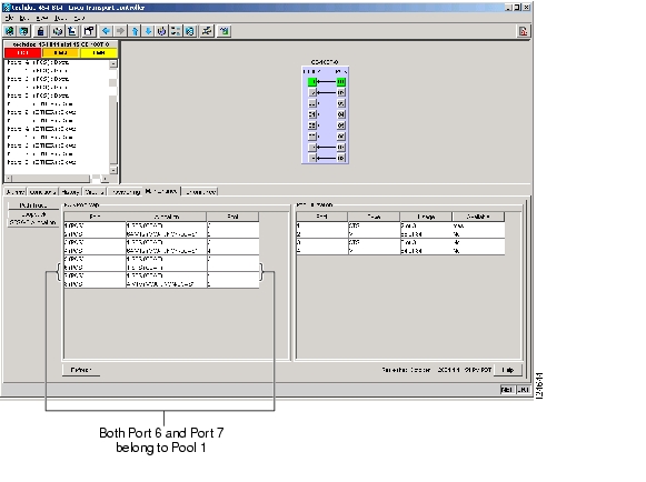
At the CTC card-level view under the Maintenance tab, the STS/VT Allocation tab ( Figure 5-30) displays how the provisioned circuits populate the four pools. This information can be useful in freeing up the bandwidth required for provisioning a circuit, if there is not enough existing capacity on any one pool for provisioning the desired circuit. You can look at the distribution of the existing circuits among the four pools and decide which circuits to delete in order to free up space for the desired circuit.
Figure 5-30 CE-100T-8 STS/VT Allocation Tab
For example, to provision an STS-3c or STS-1-3v on the CE-100T-8 card shown in Figure 5-30, a STS-3c or STS-1-3v worth of bandwidth is not available from any of the four pools. You need to delete circuits from the same pool to free up bandwidth. If the bandwidth is available but scattered among the pools, the circuit cannot be provisioned. Looking at the POS Port Map table, you can determine which circuits belong to which pools. The Pool and Port columns in Figure 5-30 show that port 6 and port 7 are both drawn from Pool 1 and no other circuits are drawn from Pool 1. Deleting these two STS-1 circuits will free up an STS-3c or STS-1-3v worth of bandwidth from a single pool.
If you did not determine what circuits to delete from the table information, you could delete the STS-1 circuits on port 3, port 5 and port 6. This frees up an STS-3c or STS-1-3v worth of bandwidth, but the required bandwidth is not available from a single pool and the STS-3c or STS-1-3v circuit is not provisionable.
The POS Port table, shown in Figure 5-30, has a row for each port with three columns. Each row shows the port number, the circuit size and type, and the pool it is drawn from. The Pool Utilization table has four columns and shows the pool number, the type of circuits on that pool, how much of the pool's capacity is being used, and whether additional capacity is available.
CE-100T-8 VCAT Characteristics
The CE-100T-8 card has hardware-based support for the ITU-T G.7042 standard link capacity adjustment scheme (LCAS). This allows you to dynamically resize a VCAT circuit through CTC or TL1 without affecting other members of the VCAT group. The CE-100T-8 card is also compatible with the ML-Series card's software-based LCAS (SW-LCAS).
The CE-100T-8 card allows independent routing and protection preferences for each member of a VCAT circuit. You can also control the amount of VCAT circuit capacity that is fully protected or unprotected. If the circuit is on a bidirectional line switched ring (BLSR), you can use protection channel access (PCA).
Alarms are supported on a per-member as well as per virtual concatenation group (VCG) basis.
Note
CE-100T-8 POS Encapsulation, Framing, and CRC
The CE-100T-8 uses Cisco EoS LEX (LEX). LEX is the primary encapsulation of ONS Ethernet cards. In this encapsulation the protocol field is set to the values specified in Internet Engineering Task Force (IETF) Request For Comments (RFC) 1841. You can provision GPF-F framing (default) or high-level data link control (HDLC) framing. With GFP-F framing, you can also configure a 32-bit CRC (the default) or no CRC (none). When LEX is used over GFP-F it is standard Mapped Ethernet over GFP-F according to ITU-T G.7041. HDLC framing provides a set 32-bit CRC.
The CE-100T-8 card supports GFP-F null mode. GFP-F CMFs are counted and discarded.
CE-100T-8 Loopback and J1 Path Trace Support
The CE-100T-8 card supports terminal and facility loopbacks. It also reports SONET alarms and transmits and monitors the J1 Path Trace byte in the same manner as OC-N cards. Support for path termination functions includes:
•
•
•
•
•
•
•
•
•
•
ML-Series Overview
The ML-Series cards integrate high-performance Ethernet transport, switching, and routing into a single card. Think of an ML-Series card as a Cisco Catalyst switch on a blade. There are two ML-Series cards:
•
•
The ML100T-12 features 12 RJ-45 interfaces and the ML1000-2 features two Small Form Factor Pluggable (SFP) slots supporting short wavelength (SX) and long wavelength (LX) optical modules. The ML100T-12 and the ML1000-2 use the same hardware and software base and offer the same feature sets.
The ML-Series card features two virtual Packet-over-SONET/SDH (POS) ports, which function in a manner similar to OC-N card ports. The SONET/SDH circuits are provisioned through CTC in the same manner as standard OC-N card circuits. The ML-Series POS ports supports virtual concatenation (VCAT) of SONET/SDH circuits and a software link capacity adjustment scheme (SW-LCAS).
An ML-Series card can be installed in slots 1-6 and 12-17 of an ONS 15454 operating with the TCC2/TCC2P and XC-10G cross-connect cards. When operating with a TCC2/TCC2P and XC or XC-VT cards, the ML-Series cards can only be installed in slots 5, 6, 12, and 13. Once installed, an ML-Series card interoperates with the cross-connect via two virtual ports. Each virtual port can support circuits up to 24c.
Each ML-Series card is an independent data switch that processes up to 5.7 Mp/s of Layer 2 and Layer 3 switching. Cards shipped with Software prior to R5.0 come preloaded with Cisco IOS Release 12.1(14)EB. Cards shipped with Software R5.0 come preloaded with Cisco IOS Release 12.2(18)SO. The Cisco IOS command-line interface (CLI) is the primary user interface for the ML-Series card. Most configuration for the card, such as Ethernet port, bridging, and VLAN, can be done only via the Cisco IOS CLI. You can access the Cisco IOS to provision the cards in three ways:
1.
2.
3.
CTC is used for ML-Series status information, SONET alarm management, Cisco IOS Telnet session initialization, Cisco IOS configuration file management, and SONET circuit provisioning. SONET cross-connects cannot be provisioned via the Cisco IOS CLI. They can only be provisioned through CTC or TL1.
The Cisco IOS software image used by the ML-Series card is permanently stored in the flash memory of the TCC2/TCC2P card, not in the Ethernet cards. During a hard reset, when an ML-Series card is physically removed and reinserted, the Cisco IOS software image is downloaded from the flash memory of the TCC2/TCC2P card to the memory cache of the ML-Series card. The cached image is then decompressed and initialized for use by the ML-Series card.
During a soft reset, when the ML-Series card is reset through CTC or Cisco IOS CLI commands, the ML-Series card checks its cache for an IOS image. If a valid and current IOS image exists, the ML-Series card decompresses and initializes the image. If the image does not exist, the ML-Series requests a new copy of the IOS image from the TCC2/TCC2P card. Caching the IOS image provides a significant time savings when a warm reset is performed.
Console Port and adaptor cable
Each ML-Series card includes a Console port labeled CONSOLE. This port is used to provide configuration access to just the associated ML-Series card's IOS features using the Cisco CLI. This port is an RJ-11 and an extension cable is available to be connected with standard Cisco console cables.
An RJ-11 to RJ-45 adaptor cable is shipped with each ML-Series card to adapt the ML-Series RJ-11 console port to any external management systems, which require RJ-45 connectors.
Figure 5-31 illustrates the console adaptor cable assembly and pin-mappings between the RJ-11 and RJ-45 ports.
The part number of the console cable for SONET is "15454-CONSOLE-02=" (Description is: RJ11 to RJ45 Console Cable Adapter, 22 Inches).
The part number of the console cable for SDH is "15454E-CONSOLE-02=" (Description is: RJ11 to RJ45 Console Cable Adapter, 22 Inches).
Figure 5-31 Console Port Adaptor Cable
ML-Series Features List
The features of the ML-Series cards are listed below.
Layer 1 Features:
•
•
•
•
•
•
•
•
•
•
•
•
•
•
Layer 2 Bridging Features:
•
•
•
•
•
•
•
VLAN Features:
•
•
•
•
•
•
•
•
•
Fast EtherChannel (FEC) Features (ML100T-12):
•
•
•
•
•
•
Gigabit EtherChannel (GEC) Features (ML1000-2):
•
•
•
•
Layer 3 Routing, Switching, and Forwarding:
•
•
•
•
•
•
•
•
•
•
Supported Routing Protocols:
•
•
•
•
•
•
•
•
•
•
•
Additional Protocols:
•
•
•
•
•
Access List (ACL) Features:
•
•
QoS Features:
•
•
•
•
•
•
•
Management Features:
•
•
•
•
•
CTC Features:
•
•
•
•
•
•
•
•
SONET Port Encapsulation
The ML-Series supports three forms of SONET port encapsulation:
1.
2.
3.
Cisco HDLC is standard on most Cisco data devices. It does not offer VLAN trunking support. PPP/BCP is a popular standard linked to RFC 2878. It supports VLAN trunking via BCP. LEX is a protocol used by the G-Series cards. This protocol supports VLAN trunking and is based on PPP over HDLC.
This allows the ML-Series to connect to the OC-N ports of switches and routers supporting POS, as well as the G-Series Ethernet cards on the Cisco ONS 15454 MSPP. All three formats support bridging and routing, standard SONET payload scrambling, and HDLC frame check sequence.
Link Aggregation (FEC, GEC, and POS)
The ML-Series offers Fast EtherChannel, Gigabit EtherChannel, and Packet-over-SONET (POS) channel link aggregation. Link aggregation groups multiple ports into a larger logical port and provides resiliency during the failure of any individual ports. The ML-Series supports a maximum of 4 Ethernet ports in Fast EtherChannel, 2 Ethernet ports in Gigabit EtherChannel, and 2 SONET/SDH virtual ports in the POS channel. The POS channel is only supported with LEX encapsulation.
Traffic flows map to individual ports based on MAC source address (SA)/destination address (DA) for bridged packets and IP SA/DA for routed packets. There is no support for policing or class-based packet priorities when link aggregation is configured.
Traditionally EtherChannel is a trunking technology that groups together multiple full-duplex 802.3 Ethernet interfaces to provide fault-tolerant high-speed links between switches, routers, and servers. EtherChannel is a logical aggregation of multiple Ethernet interfaces. EtherChannel forms a single higher bandwidth routing or bridging endpoint. EtherChannel is designed primarily for host-to-switch connectivity. The ML-Series card extends this link aggregation technology to bridged POS interfaces.
Link aggregation provides the following benefits:
•
•
•
The EtherChannel interface, consisting of multiple Fast Ethernet, Gigabit Ethernet or POS interfaces, is treated as a single interface, which is called a port channel. You must perform all EtherChannel configurations on the EtherChannel interface (port channel) rather than on the individual member Ethernet interfaces. You can create the EtherChannel interface by entering the interface port-channel interface configuration command. Each ML100T-12 supports up to 7 Fast EtherChannel (FEC) interfaces or port channels (6 Fast Ethernet and 1 POS). Each ML1000-2 supports up to 2 Gigabit EtherChannel (GEC) interfaces or port channels (1 Gigabit Ethernet and 1 POS.)
EtherChannel connections are fully compatible with IEEE 802.1Q trunking and routing technologies. 802.1Q trunking can carry multiple VLANs across an EtherChannel.
Cisco's FEC technology builds upon standards-based 802.3 full-duplex Fast Ethernet to provide a reliable high-speed solution for the campus network backbone. FEC provides bandwidth scalability within the campus by providing up to 400-Mb/s full-duplex Fast Ethernet on the ML100-12.
Cisco's GEC technology provides bandwidth scalability by providing 2-Gb/s full-duplex aggregate capacity on the ML1000-2.
Cisco's POS channel technology provide bandwidth scalability by providing up to 48 STSs or VC4-16c of aggregate capacity on either the ML100-12 or the ML1000-2.
SONET Circuits
ML-Series cards feature two SONET virtual ports with a maximum combined bandwidth of STS-48. Each port carries an STS circuit with a size of STS-1, STS-3c, STS-6c, STS-9c, STS-12c, or STS-24c. The ML-Series cards support the SONET circuits listed in Table 5-16.
VPN Routing/Forwarding (VRF) Lite
VPN Routing/Forwarding Lite (VRF Lite) is an ML-Series specific implementation of a VPN routing/forwarding instance (VRF). Unlike standard VRF, VRF Lite does not contain Multi-Protocol internal BGP (MP-iBGP).
Standard VRF is an extension of IP routing that provides multiple routing instances and separate IP routing and forwarding tables for each VPN. It provides a separate IP routing and forwarding table to each VPN. VRF is used in concert with internal MP-iBGP. MP-iBGP distributes the VRF information between routers to provide Layer 3 Multiprotocol Label Switching (MPLS)-VPN. However, ML-Series VRF implementation is without MP-iBGP. With VRF Lite, the ML Series is considered as either a PE-extension or a customer equipment (CE)-extension. It is considered a PE-extension since its has VRF (but without MP-iBGP); it is considered a CE-extension since this CE can have multiple VRFs and serves many customer with one CE box.
VRF Lite stores VRF information locally and does not distribute the VRF information to connected equipment. VRF information directs traffic to the correct interfaces and subinterfaces when the traffic is received from customer routers or from service provider router(s).
VRF Lite allows an ML-Series card, acting as customer equipment, to have multiple interfaces and subinterfaces with service provider equipment. The customer ML-Series card can then service multiple customers. Normal customer equipment serves a single customer.
Under VRF Lite, an ML-Series CE can have multiple interfaces/subinterfaces with PE for different customers (while a normal CE is only for one customer). It holds VRFs (routing information) locally; it does not distribute the VRFs to its connected PE(s). It uses VRF information to direct traffic to the correct interfaces/subinterfaces when it receives traffic from customers' routers or from Internet service provider (ISP) PE router(s). Figure 5-32 shows an example of a VRF Lite configuration.
Figure 5-32 VRF Lite Example
Cisco IOS
Cisco IOS controls the data functions of the ML-Series card and comes preloaded on the ONS 15454 TCC2/TCC2P card.
You cannot update the ML-Series Cisco IOS image in the same manner as the Cisco IOS system image on a Cisco Catalyst Series. An ML-Series Cisco IOS image upgrade can only be accomplished through CTC. Cisco IOS images for the ML-Series card are available only as part of an ONS 15454 system software release. This Cisco IOS image is included on the standard ONS 15454 SONET System Software CD under the package file name M_I.bin and full file name ons15454m-i7-mz. The images are not available for download or shipped separately.
GFP-F Framing
GFP defines a standard-based mapping of different types of services onto SONET/SDH. The ML-Series and CE-Series support frame-mapped GFP (GFP-F), which is the PDU-oriented client signal adaptation mode for GFP. GFP-F maps one variable length data packet onto one GFP packet.
GFP is composed of common functions and payload specific functions. Common functions are those shared by all payloads. Payload-specific functions are different depending on the payload type. GFP is detailed in the ITU recommendation G.7041.
Interface Configuration
The main function of an ML-Series card is to relay packets from one data link to another. Consequently, you must configure the characteristics of the interfaces, which receive and send packets. Interface characteristics include, but are not limited to, IP address, address of the port, data encapsulation method, and media type.
Many features are enabled on a per-interface basis. Interface configuration mode contains commands that modify the interface operation (for example, of an Ethernet port). When you enter the interface command, you must specify the interface type and number.
The following general guidelines apply to all physical and virtual interface configuration processes:
•
•
•
•
For information on how to configure the ML-Series cards, go to the Cisco ONS 15454 SONET/SDH ML-Series Multilayer Ethernet Card Software Feature and Configuration Guide.
Packet Over SONET (POS)
Packet over SONET (POS) is a high-speed method of transporting IP traffic between two points. This technology combines the Point-to-Point Protocol (PPP) with SONET interfaces. Figure 5-33 illustrates a POS configuration between two ML-Series cards.
Figure 5-33 ML-Series Card-to-ML-Series Card POS Configuration
POS interfaces use a value of 0x16 or 0xCF in the C2 byte depending on whether ATM-style scrambling is enabled or not. RFC 2615, which defines PPP over SONET, mandates the use of these values based on scrambling settings as follows:
•
•
•
Bridging
The ML-Series card can be configured to serve as an IP router and a bridge. Cisco IOS software supports transparent bridging for Fast Ethernet, Gigabit Ethernet, and POS. Cisco IOS software functionality combines the advantages of a spanning tree bridge and a router. This combination provides the speed and protocol transparency of a spanning tree bridge, along with the functionality, reliability, and security of a router.
To configure bridging, you must perform the following tasks in the modes indicated:
In global configuration mode:
•
•
In interface configuration mode:
•
These interfaces become part of the same spanning tree, allowing the ML-Series card to bridge all non-routed traffic among the network interfaces comprising the bridge group. Interfaces not participating in a bridge group cannot forward bridged traffic.
If the destination address of the packet is known in the bridge table, the packet is forwarded on a single interface in the bridge group. If the packet's destination is unknown in the bridge table, the packet is flooded on all forwarding interfaces in the bridge group. The bridge places source addresses in the bridge table as it learns them during the process of bridging.
A separate spanning tree process runs for each configured bridge group. Each bridge group participates in a separate spanning tree. A bridge group establishes a spanning tree based on the bridge protocol data units (BPDUs) it receives on only its member interfaces.
Spanning Tree Support
The ML-Series supports the per-VLAN spanning tree (PVST+) and a maximum of 255 spanning tree instances.
IEEE 802.1T Spanning Tree Extensions
The ML-Series cards support the IEEE 802.1T spanning tree extensions, and some of the bits previously used for the switch priority are now used as the bridge ID. The result is that fewer MAC addresses are reserved for the switch, and a larger range of VLAN IDs can be supported, all while maintaining the uniqueness of the bridge ID. As shown in Table 5-17, the two bytes previously used for the switch priority are reallocated into a 4-bit priority value and a 12-bit extended system ID value equal to the bridge ID. In earlier releases of spanning tree the switch priority is a 16-bit value.
Spanning tree uses the extended system ID, the switch priority, and the allocated spanning tree MAC address to make the bridge ID unique for each VLAN.
Creating the Spanning Tree Topology
When the spanning tree topology is calculated based on default parameters, the path between source and destination end stations in a switched network might not be ideal. For instance, connecting higher-speed links to an interface that has a higher number than the root port can cause a root-port change. The goal is to make the fastest link the root port as shown in the following example.
In Figure 5-34, A is elected as the root switch because the switch priority of all the switches is set to the default (32768) and A has the lowest MAC address. However, because of traffic patterns, number of forwarding interfaces, or link types, A might not be the ideal root switch. By increasing the priority (lowering the numerical value) of the ideal switch so that it becomes the root switch, you force a spanning tree recalculation to form a new topology with the ideal switch as the root.
Figure 5-34 Spanning Tree Topology
Spanning Tree Interface States
Propagation delays can occur when protocol information passes through a switched LAN. As a result, topology changes can take place at different times and at different places in a switched network. When an interface transitions directly from nonparticipation in the spanning tree topology to the forwarding state, it can create temporary data loops. Interfaces must wait for new topology information to propagate through the switched LAN before starting to forward frames. They must allow the frame lifetime to expire for forwarded frames that have used the old topology.
Figure 5-35 illustrates how an interface moves through the states.
Figure 5-35 Spanning Tree Interface States
When you power up the ML-Series card, STP is enabled by default, and every interface in the switch, VLAN, or network goes through the blocking state and the transitory states of listening and learning. Spanning tree stabilizes each interface at the forwarding or blocking state.
When the spanning tree algorithm places a Layer 2 interface in the forwarding state, this process occurs:
1.
2.
3.
4.
Spanning Tree Address Management
IEEE 802.1D specifies 17 multicast addresses, ranging from 0x00180C2000000 to 0x0180C2000010, to be used by different bridge protocols. These addresses are static addresses that cannot be removed.
The ML-Series card switches supported BPDUs (0x0180C2000000 and 01000CCCCCCD) when they are being tunneled via the protocol tunneling feature.
STP and IEEE 802.1Q Trunks
When you connect a Cisco switch to a non-Cisco device through an 802.1Q trunk, the Cisco switch uses PVST+ to provide spanning tree interoperability. PVST+ is automatically enabled on 802.1Q trunks after users assign a protocol to a bridge group. The external spanning tree behavior on access ports and Inter-Switch Link (ISL) trunk ports is not affected by PVST+.
Spanning Tree and Redundant Connectivity
You can create a redundant backbone with spanning tree by connecting two ML-Series interfaces to another device or to two different devices. Spanning tree automatically disables one interface but enables it if the other one fails. If one link is high speed and the other is low speed, the low-speed link is always disabled. If the speeds are the same, the port priority and port ID are added together, and spanning tree disables the link with the lowest value.
You can also create redundant links between switches by using EtherChannel groups.
Accelerated Aging to Retain Connectivity
The default for aging dynamic addresses is 5 minutes, which is the default setting of the bridge bridge-group-number aging-time global configuration command. However, a spanning tree reconfiguration can cause many station locations to change. Because these stations could be unreachable for 5 minutes or more during a reconfiguration, the address-aging time is accelerated so that station addresses can be dropped from the address table and then relearned.
Because each VLAN is a separate spanning tree instance, the switch accelerates aging on a per-VLAN basis. A spanning tree reconfiguration on one VLAN can cause the dynamic addresses learned on that VLAN to be subject to accelerated aging. Dynamic addresses on other VLANs can be unaffected and remain subject to the aging interval entered for the switch.
Rapid Spanning Tree (RSTP) Support
ML-Series cards support per-VLAN rapid spanning tree (PVRST) and a maximum of 255 rapid spanning tree instances.
The RSTP provides rapid convergence of the spanning tree by assigning port roles and by determining the active topology. The RSTP builds upon the IEEE 802.1D STP to select the switch with the highest switch priority (lowest numerical priority value).
In a stable topology with consistent port roles throughout the network, the RSTP ensures that every root port and designated port immediately transition to the forwarding state while all alternate and backup ports are always in the discarding state (equivalent to blocking in 802.1D). The port state controls the operation of the forwarding and learning processes. Table 5-18 provides a comparison of 802.1D and RSTP port states.
Rapid Convergence
The RSTP provides for rapid recovery of connectivity following the failure of a ML-Series card, a a ML-Series port, or a LAN. It provides rapid convergence for new root ports and ports connected through point-to-point links as follows:
•
•
Synchronization of Port Roles
When the ML-Series card receives a proposal message on one of its ports and that port is selected as the new root port, the RSTP forces all other ports to synchronize with the new root information. The ML-Series card is synchronized with superior root information received on the root port if all other ports are synchronized.
If a designated port is in the forwarding state, it transitions to the blocking state when the RSTP forces it to synchronize with new root information. In general, when the RSTP forces a port to synchronize with root information and the port does not satisfy any of the above conditions, its port state is set to blocking.
After ensuring all of the ports are synchronized, the ML-Series card sends an agreement message to the designated switch corresponding to its root port. When the ML-Series cards connected by a point-to-point link are in agreement about their port roles, the RSTP immediately transitions the port states to forwarding.
Bridge Protocol Data Unit Format and Processing
The RSTP BPDU format is the same as the IEEE 802.1D BPDU format except that the protocol version is set to 2. A new Length field is set to zero, which means that no version 1 protocol information is present. Table 5-19 shows the RSTP flag fields.
The sending ML-Series port sets the proposal flag in the RSTP BPDU to propose itself as the designated switch on that LAN. The port role in the proposal message is always set to the designated port. The sending ML-Series port sets the agreement flag in the RSTP BPDU to accept the previous proposal. The port role in the agreement message is always set to the root port.
The RSTP does not have a separate topology change notification (TCN) BPDU. It uses the topology change (TC) flag to show the topology changes. However, for interoperability with 802.1D switches, the RSTP switch processes and generates TCN BPDUs.
The learning and forwarding flags are set according to the state of the sending port.
Processing Superior BPDU Information
If a ML-Series port receives superior root information (lower bridge ID, lower path cost, etc.) than currently stored for the port, the RSTP triggers a reconfiguration. If the port is proposed and is selected as the new root port, RSTP forces all the other ports to synchronize.
If the BPDU received is an RSTP BPDU with the proposal flag set, the switch sends an agreement message after all of the other ports are synchronized. If the BPDU is an 802.1D BPDU, the ML-Series card does not set the proposal flag and starts the forward-delay timer for the port. The new root port requires twice the forward-delay time to transition to the forwarding state.
If the superior information received on the port causes the port to become a backup or alternate port, RSTP sets the port to the blocking state but does not send the agreement message. The designated port continues sending BPDUs with the proposal flag set until the forward-delay timer expires, at which time the port transitions to the forwarding state.
Processing Inferior BPDU Information
If a designated ML-Series port receives an inferior BPDU (higher bridge ID, higher path cost, etc., than currently stored for the port) with a designated port role, it immediately replies with its own information.
Topology Changes
This section describes the differences between the RSTP and the IEEE 802.1D in handling spanning tree topology changes.
•
•
•
•
•
When a port is initialized, the timer is started (which specifies the minimum time during which RSTP BPDUs are sent), and RSTP BPDUs are sent. While this timer is active, the ML-Series card processes all BPDUs received on that port and ignores the protocol type.
If the ML-Series card receives an IEEE 802.1D BPDU after the port's migration-delay timer has expired, it assumes that it is connected to an IEEE 802.1D switch and starts using only IEEE 802.1D BPDUs. However, if the RSTP ML-Series card is using IEEE 802.1D BPDUs on a port and receives an RSTP BPDU after the timer has expired, it restarts the timer and starts using RSTP BPDUs on that port.
Interoperability with IEEE 802.1D STP
An ML-Series card running RSTP supports a built-in protocol migration mechanism that enables it to interoperate with legacy IEEE 802.1D switches. If this card receives a legacy IEEE 802.1D configuration BPDU (a BPDU with the protocol version set to 0), it sends only 802.1D BPDUs on that port.
However, the ML-Series card does not automatically revert to the RSTP mode if it no longer receives IEEE 802.1D BPDUs, because it cannot determine whether the legacy switch has been removed from the link unless the legacy switch is the designated switch. Also, an ML-Series card might continue to assign a boundary role to a port when the card to which it is connected has joined the region.
VLAN Support
ML-Series software supports port-based VLANs and VLAN trunk ports, which are ports that carry the traffic of multiple VLANs. Each frame transmitted on a trunk link is tagged as belonging to only one VLAN.
ML-Series software supports VLAN frame encapsulation through the IEEE 802.1Q standard on both the ML100T-12 and the ML1000-2. The Cisco ISL VLAN frame encapsulation is not supported. ISL frames will be broadcast at Layer 2, or dropped at Layer 3.
ML-Series switching supports up to 900 VLAN subinterfaces per card (for example, 200 VLANs on 4 interfaces uses 800 VLAN subinterfaces). A maximum of 255 logical VLANs can be bridged per card (limited by the number of bridge-groups). Each VLAN subinterface can be configured for any VLAN ID in the full 1-4095 range. Figure 5-36 shows a network topology in which two VLANs span two ONS 15454 nodes with ML-Series cards.
Figure 5-36 VLANs Spanning Devices in a Network
IEEE 802.1Q VLAN Encapsulation
On an IEEE 802.1Q trunk port, all transmitted and received frames are tagged except for those on the VLAN configured as the native VLAN for the port. Frames on the native VLAN are always transmitted untagged and are normally received untagged. You can configure VLAN encapsulation on both the ML100T-12 and the ML1000-2.
On an IEEE 802.1Q trunk port, all transmitted and received frames are tagged except for those on the VLAN configured as the native VLAN for the port. On ML-Series cards, the native VLAN is always VLAN ID 1. Frames on the native VLAN are normally transmitted untagged and are normally received untagged. Tagging of transmitted native VLAN frames can be forced by the global configuration command vlan dot1q tag native. VLAN encapsulation is supported on both the ML100T-12 and the ML1000-2. VLAN encapsulation is supported for routing and bridging, and is supported on Ethernet interfaces and on POS interfaces with PPP and LEX encapsulation.
IEEE 802.1Q and Layer 2 Protocol Tunneling
Virtual private networks (VPNs) provide enterprise-scale connectivity on a shared infrastructure, often Ethernet-based, with the same security, prioritization, reliability, and manageability requirements of private networks. Tunneling is a feature designed for service providers who carry traffic of multiple customers across their networks and are required to maintain the VLAN and Layer 2 protocol configurations of each customer without impacting the traffic of other customers. The ML-Series cards support IEEE 802.1Q tunneling and Layer 2 protocol tunneling.
Business customers of service providers often have specific requirements for VLAN IDs and the number of VLANs to be supported. The VLAN ranges required by different customers in the same service-provider network might overlap, and traffic of customers through the infrastructure might be mixed. Assigning a unique range of VLAN IDs to each customer would restrict customer configurations and could easily exceed the VLAN limit of 4096 of the IEEE 802.1Q specification.
Using the IEEE 802.1Q tunneling feature, you can use a single VLAN to support customers who have multiple VLANs. Customer VLAN IDs are preserved and traffic from different customers is segregated within the service-provider infrastructure even when they appear to be on the same VLAN. The IEEE 802.1Q tunneling expands VLAN space by using a VLAN-in-VLAN hierarchy and tagging the tagged packets. A port configured to support IEEE 802.1Q tunneling is called a tunnel port. When you configure tunneling, you assign a tunnel port to a VLAN that is dedicated to tunneling. Each customer requires a separate VLAN, but that VLAN supports all of the customer's VLANs.
Customer traffic tagged in the normal way with appropriate VLAN IDs comes from an IEEE 802.1Q trunk port on the customer device and into a tunnel port on the ML-Series card. The link between the customer device and the ML-Series card is an asymmetric link because one end is configured as an IEEE 802.1Q trunk port and the other end is configured as a tunnel port. You assign the tunnel port interface to an access VLAN ID unique to each customer. See Figure 5-37.
Figure 5-37 IEEE 802.1Q Tunnel Ports in a Service-Provider Network
Packets coming from the customer trunk port into the tunnel port on the ML-Series card are normally IEEE 802.1Q-tagged with appropriate VLAN ID. The tagged packets remain intact inside the ML-Series card and, when they exit the trunk port into the service provider network, are encapsulated with another layer of an IEEE 802.1Q tag (called the metro tag) that contains the VLAN ID unique to the customer. The original IEEE 802.1Q tag from the customer is preserved in the encapsulated packet. Therefore, packets entering the service-provider infrastructure are double-tagged, with the outer tag containing the customer's access VLAN ID, and the inner VLAN ID being the VLAN of the incoming traffic.
When the double-tagged packet enters another trunk port in a service provider ML-Series card, the outer tag is stripped as the packet is processed inside the switch. When the packet exits another trunk port on the same core switch, the same metro tag is again added to the packet. Figure 5-38 shows the structure of the double-tagged packet.
Figure 5-38 Normal, IEEE 802.1Q, and 802.1Q Tunneled Ethernet Packet Formats
When the packet enters the trunk port of the service-provider egress switch, the outer tag is again stripped as the packet is processed internally on the switch. However, the metro tag is not added when it is sent out the tunnel port on the edge switch into the customer network, and the packet is sent as a normal IEEE 802.1Q-tagged frame to preserve the original VLAN numbers in the customer network.
In Figure 5-37, Customer A was assigned VLAN 30, and Customer B was assigned VLAN 40. Packets entering the ML-Series card tunnel ports with IEEE 802.1Q tags are double-tagged when they enter the service-provider network, with the outer tag containing VLAN ID 30 or 40, appropriately, and the inner tag containing the original VLAN number, for example, VLAN 100. Even if both Customers A and B have VLAN 100 in their networks, the traffic remains segregated within the service-provider network because the outer tag is different. With IEEE 802.1Q tunneling, each customer controls its own VLAN numbering space, which is independent of the VLAN numbering space used by other customers and the VLAN numbering space used by the service-provider network.
At the outbound tunnel port, the original VLAN numbers on the customer's network are recovered. If the traffic coming from a customer network is not tagged (native VLAN frames), these packets are bridged or routed as if they were normal packets, and the metro tag is added (as a single-level tag) when they exit toward the service provider network.
If using the native VLAN (VLAN 1) in the service provider network as a metro tag, it is important that this tag always be added to the customer traffic, even though the native VLAN ID is not normally added to transmitted frames. If the VLAN 1 metro tag were not added on frames entering the service provider network, then the customer VLAN tag would appear to be the metro tag, with disastrous results. The global configuration command vlan dot1q tag native must be used to prevent this by forcing a tag to be added to VLAN 1. Avoiding the use of VLAN 1 as a metro tag transporting customer traffic is recommended to reduce the risk of misconfiguration. A best practice is to use VLAN 1 as a private management VLAN in the service provider network.
The IEEE 802.1Q class of service (COS) priority field on the added metro tag is set to zero by default, but may be modified by input or output policy maps.
ML-Series QoS
The ML-Series card incorporates QoS features to provide control over access to network bandwidth resources. This control enables you to implement priorities specified in Service Level Agreements (SLAs) and offers tools to enable traffic engineering.
The ML-Series QoS provides the ability to classify each packet in the network based on its interface of arrival, bridge group, class of service (CoS), IP precedence, and IP differentiated services code points. When classified, further QoS functions can be applied to each packet as it traverses the network.
Policing is also provided by the ML-Series card to ensure that no attached equipment submits more than a pre-defined amount of bandwidth into the network. This feature limits the bandwidth available to a customer, and provides a mechanism to support traffic engineering.
Priority marking allows Ethernet IEEE 802.1P CoS bits to be marked, as they exit the ML-Series card. This feature operates on the outer IEEE 802.1P tag when coupled with QinQ.
Per class flow queuing is provided to enable fair access to excess network bandwidth, and low latency queuing is supported for voice traffic. It allows allocation of bandwidth to support service-level agreements and ensure applications with high network resource requirements are adequately served. Buffers are allocated to queues dynamically from a shared resource pool. The allocation process incorporates the instantaneous system load as well as the allocated bandwidth to each queue to optimize buffer allocation to each queue.
The ML-Series card uses an advanced Weighted Deficit Round Robin (WDRR) scheduling process to provide fair access to excess bandwidth as well as guaranteed throughput to each class flow.
Admission control is a process that is invoked each time that service is configured on the ML-Series card to ensure that the card's available QoS resources are not overcommitted. In particular, admission control ensures that no configurations are accepted where a sum of the committed bandwidths on an interface exceed the total bandwidth of that interface.
The QoS bandwidth allocation of Multicast and Broadcast traffic is handled separately and differently than Unicast traffic. Aggregate Multicast and Broadcast traffic are given a fixed bandwidth commit of 10% on each interface, and treated as best effort for traffic exceeding 10%. Multicast and Broadcast are supported at line-rate.
Understanding CoS-based Packet Statistics (Software Release 4.6 and Later)
Enhanced performance monitoring displays per-CoS packet statistics on the ML-Series card interfaces when CoS accounting is enabled. Starting with software Release 4.6 per-CoS packet statistics are only supported for bridged services, not IP routing or MPLS. CoS-based traffic utilization is displayed at the FastEthernet or GigabitEthernet interface or subinterface (VLAN) level or the POS interface level but not at the POS subinterface level. RPR statistics are not available at the SPR interface level, but statistics are available for the individual POS ports that make up the SPR interface. EtherChannel (port-channel) and BVI statistics are available only at the member port level. Table 5-20 shows the types of statistics available at specific interfaces.
Table 5-20 Packet Statistics on ML-Series Card Interfaces
Input - Packets and Bytes
Yes
Yes
No
No
Output - Packets and Bytes
Yes
Yes
No
No
Drop Count - Packets and Bytes1
Yes
No
Yes
No
1 Drop counts only include discards caused by output congestion and are counted at the output interface.
CoS-based packet statistics are available through the Cisco IOS command-line interface (CLI) and simple network management protocol (SNMP), using an extension of the CISCO-PORT-QOS MIB. They are not available through Cisco Transport Controller (CTC).
Classification
Classification can be based on any single packet classification criteria or a combination (logical And and OR). A total of 254 classes, not including the class default, can be defined on the card. Classification of packets is configured using the Modular CLI class-map command. For traffic transiting the resilient packet ring (RPR), only the Input Interface and/or the RPR-CoS can be used as classification criteria.
Policing
Dual leaky bucket policer is a process where the first bucket (CIR bucket) is filled with tokens at a known rate (CIR), which is a parameter that can be configured by the operator. Figure 5-39 illustrates the dual leaky bucket policer model. The tokens fill the bucket up to a maximum level, which is the amount of burstable committed (BC) traffic on the policer. The non-conforming packets of the first bucket are the overflow packets, which are passed to the second leaky bucket (the PIR bucket). The second leaky bucket is filled with these tokens at a known rate (PIR), which is a parameter that can be configured by the operator. The tokens fill the PIR bucket up to a maximum level (BP), which is the amount of peak burstable traffic on the policer. The non-conform packets of the second bucket are the overflow packets, which can be dropped or marked according to the policer definition.
On the dual leaky bucket policer, the packets conforming to the CIR are conform packets, the packets not conforming to CIR but conforming to PIR are exceed packets, and the packets not conforming to either the PIR or CIR are violate packets.
Figure 5-39 Dual Leaky Bucket Policer Model
Marking and Discarding
On the ML-Series card's policer, the conform packets can be transmitted or marked and transmitted. The exceed packets can be transmitted, marked and transmitted, or dropped. The violating packets can be transmitted, marked and transmitted, or dropped. The primary application of the dual-rate or three-color policer is to mark the conform packets with CoS bit 2l, mark the exceed packet with CoS bit 1, and discard the violated packets so all the subsequent network devices can implement the proper QoS treatment per frame/packet basis based on these priority marking without knowledge of each SLA.
If a marked packet has a provider-supplied Q-Tag inserted before transmission, the marking only affects the provider Q-Tag. If a Q-Tag was received, it will be re-marked. If a marked packet is transported over the RPR ring, the marking also affects the RPR-CoS bit.
If a Q-Tag is inserted (QinQ), the marking affects the added Q-Tag. If the ingress packet contains a Q-tag and is transparently switched, the existing Q-Tag is marked. In case of a packet without any Q-Tag, the marking does not have any significance.
The local scheduler treats all non-conforming packets as discard eligible regardless of their CoS setting or the global cos commit definition. For RPR implementation, the discard eligible (DE) packets are marked using the DE bit on the RPR header. The discard eligibility based on the CoS Commit or the policing action is local to the ML-Series card scheduler, but it is global for the RPR ring.
Queuing
ML-Series card queuing uses a shared buffer pool to allocate memory dynamically to different traffic queues. The ML-Series card uses a total of 12 MB memory for the buffer pool. Ethernet ports share 6 MB of the memory, and POS ports share the remaining 6 MBs of memory. Memory space is allocated in 1500-byte increments.
Each queue has an upper limit on the allocated number of buffers based on the class bandwidth
assignment of the queue and the number of queues configured. This upper limit is typically 30% to 50% of the shared buffer capacity. Dynamic buffer allocation to each queue may be reduced based on the number of queues needing extra buffering. The dynamic allocation mechanism provides fairness in proportion to service commitments as well as optimization of system throughput over a range of system traffic loads.
The Low Latency Queue (LLQ) is defined by setting the weight to infinity or committing 100% bandwidth. When a LLQ is defined, a policer should also be defined on the ingress for that specific class to limit the maximum bandwidth consumed by the LLQ; otherwise there may be a potential risk of LLQ occupying the whole bandwidth and starving the other unicast queues.
The ML-Series includes support for 400 user-definable queues, which are assigned per the classification and bandwidth allocation definition. The classification used for scheduling classifies the frames/packet after the policing action, so if the policer is used to mark or change the CoS bits of the ingress frames/packet, the new values are applicable for the classification of traffic for queuing and scheduling. The ML-Series provides buffering for 4000 packets.
Scheduling
Scheduling is provided by a series of schedulers that perform a weighted deficit round robin (WDRR) as well as priority scheduling mechanisms from the queued traffic associated with each egress port.
Though ordinary round robin servicing of queues can be done in constant time, the unfairness that occurs when different queues use different packet sizes. Deficit Round Robin (DRR) scheduling solves this problem. If a queue was not able to send a packet in its previous round because its packet size was too large, the remainder from the previous amount of credits a queue gets in each round (quantum) is added to the quantum for the next round.
WDRR extends the quantum idea from the DRR to provide weighted throughput for each queue. Different queues have different weights, and the quantum assigned to each queue in its round is proportional to the relative weight of the queue among all the queues serviced by that scheduler.
Weights are assigned to each queue as a result of the service provisioning process. When coupled with policing and policy mapping provisioning, these weights and the WDRR scheduling process ensure that QoS commitments are provided to each service flow.
Figure 5-40 illustrates the ML-Series card's queuing and scheduling.
Figure 5-40 Queuing and Scheduling Model
The weighting structure allows traffic to be scheduled at 1/2048 of the port rate. This equates to approximately 488 kbps for traffic exiting a Gigabit Ethernet port, approximately 293 kbps for traffic going exiting an OC-12c port, and approximately 49 kbps for traffic exiting a FastEthernet port.
The multicast/broadcast queue is automatically created on every egress port of the ML-Series card with a committed bandwidth of 10%. This queue is used for multicast/broadcast data traffic, control traffic, L2 protocol tunnelling, and flooding traffic of the unknown MAC during MAC learning. If the aggregate of multicast/broadcast traffic at any egress port exceeds 10% of the bandwidth those frames beyond 10% of the bandwidth, are treated as best effort by the scheduler.
The unicast queues are created as the output service policy implementation on the egress ports. Each unicast queue is assigned with a committed bandwidth and the weight of the queue is determined by the normalization of committed bandwidth of all defined unicast queues for that port. The traffic beyond the committed bandwidth on any queue is treated by the scheduler according to the relative weight of the queue.
The LLQ is created as the output service policy implementation on the egress ports. Each LLQ queue is assigned with a committed bandwidth of 100% and is served with lower latency. To limit the bandwidth usage by the LLQ, a strict policer needs to be implemented on the ingress for the LLQ traffic classes.
The discard eligibility (DE) allows some packets to be treated as committed and some as discard-eligible on the scheduler. For the Ethernet frames the CoS (802.1p) bits are used to identify committed and discard eligible packets, where the RPR-CoS and the DE bits are used for RPR traffic. When congestion occurs and a queue begins to fill, the discard-eligible packets hit a lower tail-drop threshold than the committed packets. Committed packets are not dropped until the total committed load exceeds the interface output. The tail-drop thresholds adjust dynamically in the card to maximize use of the shared buffer pool while guaranteeing fairness under all conditions.
Multicast QoS
On the ML-Series cards, multicast (including IP-multicast) and broadcast traffic forwarding is supported at line-rate; however the QoS implementation on multicast traffic varies from the unicast QoS. The difference is in the priority handling for the multicast traffic on the scheduler.
For unicast packets, the priority is defined by the bandwidth command, which creates a CIR for the unicast packets in a particular class.
The priority handling of multicast packets is not based on the bandwidth command. Instead, multicast frames are assigned to a queue that has a committed bandwidth of 10% of the port bandwidth. If the multicast and broadcast traffic exceeds 10% of the port bandwidth, frames exceeding 10% are given low priority (best effort). The10% committed bandwidth for multicast is applied to the aggregate traffic and does not allow the multicast traffic of one customer to be given higher priority than another customer, unlike the QoS model for unicast traffic.
The scheduler allocates 10% of the bandwidth for multicast and broadcast traffic. Any other QoS implementation is not applicable for multicast and broadcast traffic except the allocation of 10% bandwidth for all multicast/broadcast traffics. Buffers are allocated to queues dynamically from a shared resource pool.
Control Packets and L2 Tunneled Protocols
The control packets originated by the ML-Series card have a higher priority than data packets. The external Layer 2 and Layer 3 control packets are handled as data packets and assigned to broadcast queues. Bridge protocol data unit (BPDU) prioritization in the ML-Series card gives Layer 2-tunneled BPDU sent out the multicast/broadcast queue a higher discard value and therefore a higher priority than than other packets in the multicast/broadcast queue. The Ethernet CoS (802.1p) for Layer 2-tunneled protocols can be assigned by the ML-Series card.
Priority Marking
Priority marking allows the operator to assign the 802.1p CoS bits of packets that exit the card. This marking allows the operator to use the CoS bits as a mechanism for signaling to downstream nodes the QoS treatment the packet should be given. This feature operates on the outer-most 802.1p CoS field. When used with the QinQ feature, priority marking allows the user traffic (inner Q-Tag) to traverse the network transparently, while providing a means for the network to internally signal QoS treatment at Layer 2.
Priority marking follows the classification process, and therefore any of the classification criteria identified earlier can be used as the basis to set the outgoing 802.1p CoS field. For example, a specific CoS value can be mapped to a specific Bridge Group.
Priority marking is configured using the MQC set-cos command. If packets would otherwise leave the card without an 802.1q tag, then the set cos will have no effect on that packet. If an 802.1q tag is inserted in the packet (either a normal tag or a QinQ tag), the inserted tag will have the set cos priority. If an 802.1q tag is present on packet ingress and retained on packet egress, the priority of that tag will be modified. If the ingress interface is an Q-in-Q Access port, and the set cos policy-map classifies based on ingress tag priority, this will classify based on the user priority. This is a way to allow the user-tag priority to determine the Service Provider tag priority. When a packet does not match any set cos policy-map, the priority of any preserved tag is unchanged and the priority of any inserted 802.1q tag is set to 0.
The set-cos command on the output service policy is only applied to unicast traffic. Priority marking for multicast/broadcast traffic can only be achieved by the set cos action of the policing process on the input service policy.
QinQ Implementation
The hierarchical VLAN or IEEE 802.1Q tunneling feature enables the service provider to transparently carry the customer VLANs coming from any specific port (UNI) and transport them over the service provider network. This feature is also known as QinQ, which is performed by adding an additional 802.1Q tag on every customer frame.
Using the QinQ feature, service providers can use a single VLAN to support customers with multiple VLANs. QinQ preserves customer VLAN IDs and segregates traffic from different customers within the service-provider infrastructure, even when traffic from different customers originally shared the same VLAN ID. The QinQ also expands VLAN space by using a VLAN-in-VLAN hierarchy and tagging the tagged packets. When the service provider tag is added, the QinQ network typically loses any visibility to the IP header or the customer Ethernet 802.1Q tag on the QinQ encapsulated frames.
On the ML-Series cards, the QinQ access ports (802.1Q tunnel ports or QinQ UNI ports) have visibility to the customer CoS and the IP Precedence or IP DSCP values; therefore, the SP tag can be assigned with proper CoS bit which would reflect the customer IP Precedence, IP DSCP, or CoS bits. In the QinQ network, the QoS is then implemented based on the 802.1p bit of the service provider tag. The ML-Series cards do not have visibility into the customer CoS or IP Precedence or DSCP values after the packet is double-tagged (that is beyond the entry point of the QinQ service).
Figure 5-41 illustrates the QinQ implementation on the ML-Series card.
Figure 5-41 Q in Q
The ML-Series cards can be used as the 802.1Q tunneling device for the QinQ network and also provide the option to copy the customer frame's CoS bit into the CoS bit of the added QinQ tag. This way the service provider QinQ network can be fully aware of the necessary QoS treatment for each individual customer frames.
Flow Control Pause and QoS
If flow control and port-based policing are both enabled for an interface, flow control handles the bandwidth. If the policer gets non-compliant flow, then the policer drops or demarks the packets using the policer definition of the interface.
QoS on RPR
For VLAN bridging over RPR, all ML-Series cards on the ring must be configured with the base RPR and RPR QOS configuration. SLA and bridging configurations are only needed at customer RPR access points, where 802.1q VLAN CoS is copied to the RPR CoS. This 802.1q VLAN CoS copying can be overwritten with a set cos <action> command. The cos commit rule applies at RPR ring ingress. Transit RPR ring traffic is classified on CoS only.
If the packet does not have a VLAN header, the RPR CoS for non-VLAN traffic is set using the following rules:
1.
2.
3.
4.
The RPR header contains a CoS value and DE indicator. The RPR DE is set for non-committed traffic.
Resilient Packet Ring (RPR)
RPR is an emerging network architecture designed for metro fiber ring networks. This new MAC protocol is designed to overcome the limitations of IEEE 802.1D Spanning Tree Protocol (STP), IEEE 802.1W Rapid Spanning Tree Protocol (RSTP) and SONET in packet-based networks. RPR operates at the Layer 2 level and is compatible with Ethernet and SONET/SDH.
The ML-Series card's RPR relies on the QoS features of the ML-Series card for efficient bandwidth utilization with service level agreement (SLA) support. ML-Series card QoS mechanisms apply to all SONET traffic on the ML-Series card, whether passed-through, bridged, or stripped.
When an ML-Series card is configured with RPR and made part of a shared packet ring (SPR), the ML-Series card assumes it is part of a ring. If a packet is not destined for devices attached to the specific ML-Series, the ML-Series card simply continues to forward this transit traffic along the SONET circuit relying on the circular path of the ring architecture to guarantee the packet will eventually arrive at the destination. This eliminates the need to queue and forward the packet flowing through the non-destination ML-Series card. From a Layer 2 or Layer 3 perspective, the entire RPR looks like one shared network segment.
RPR supports operation over protected and unprotected SONET circuits. On unprotected SONET circuits RPR provides SONET -like protection without the redundant SONET protection path. Eliminating the need for a redundant SONET path frees bandwidth for additional traffic. RPR also incorporates spatial reuse of bandwidth through a hash algorithm for east/west packet transmission. RPR utilizes the entire ring bandwidth and does not need to block ring segments like STP or RSTP.
Packet Handling Operations
The RPR protocol, using the transmitted packet's header information, allows the interfaces to quickly determine the operation that needs to be applied to the packet. An ML-Series card configured with RPR is part of the ring and has three basic packet-handling operations: bridge, pass-through, or strip. Figure 5-42 illustrates these operations. Bridging connects and passes packets between the Ethernet ports on the ML-Series and the Packet over SONET/SDH (POS) circuit circling the ring. Pass-through lets the packets continue through the ML-Series card and along the ring, and stripping takes the packet off the ring and discards it. Because STP or RSTP is not in effect between nodes when RPR is configured, the transmitting RPR port strips its own packets after they return from circling the ring. A hash algorithm is used to determine the direction of the packet around the RPR.
Figure 5-42 RPR Packet Handling Operations
Ring Wrapping
RPR initiates ring wraps in the event of a fiber cut, node failure, node restoration, new node insertion, or other traffic problems. This protection mechanism redirects traffic to the original destination by sending it in the opposite direction around the ring after a link state change or after receiving SONET path level alarms. Ring wrapping on the ML-Series card allows sub 50-msec convergence times. RPR convergence times are comparable to SONET and much faster than STP or RSTP.
RPR on the ML-Series card survives both unidirectional and bidirectional transmission failures within the ring. Unlike STP or RSTP, RPR restoration is scalable, increasing the number of ML-Series cards in a ring does not increase the convergence time.
RPR will initiate ring wraps immediately (default) or delay the wrap with a configured carrier delay time. When configured to wrap traffic after the carrier delay, a POS trigger delay time should be added to the carrier delay time to estimate approximate convergence times. The default and minimum POS trigger delay time for the ML-Series Card is 200 ms. A carrier delay time of 200 ms (default) and a POS trigger delay time of 200 ms (default and minimum) combine for a total convergence time of approximately 400 ms. If the carrier delay is set to 0, then the convergence time would be approximately 200 ms. Figure 5-43 illustrates ring wrapping.
Figure 5-43 RPR Ring Wrapping
Dual RPR Interconnect
The bridge-group protocol DRPRI is an RPR mechanism that interconnects rings for protection during an ONS 15454 node failure. Interconnecting ONS 15454 nodes do not have to be adjacent to the RPR. The protocol provides two parallel connections of the rings linked by a special instance of RSTP. One connection is the active node and the other is the standby node. During a failure of the active node, link, or card, a proprietary algorithm detects the failure and causes a switchover to the standby node. Figure 5-44 shows two access rings interconnected to a core ring via DRPRI.
Figure 5-44 Dual RPR Interconnect (DRPRI)
DRPRI provides a less than 200-msec recovery time for Layer 2 bridged traffic when the ML-Series cards use the enhanced microcode image. The Layer 2 recovery time is up to 12 seconds for other microcode images. The recovery time for Layer 3 unicast and multicast traffic also depends on the convergence time of the routing protocol implemented regardless of the microcode image used.
Understanding EoMPLS
EoMPLS provides a tunneling mechanism for Ethernet traffic through an MPLS-enabled Layer 3 core. It encapsulates Ethernet protocol data units (PDUs) inside MPLS packets and using label stacking forwards them across the MPLS network. EoMPLS is an Internet Engineering Task Force (IETF) standard-track protocol based on the Martini draft, specifically the draft-martini-l2circuit-encap-mpls-01 and draft-martini-l2circuit-transport-mpls-05 sections.
EoMPLS allows service providers to offer customers a virtual Ethernet line service or VLAN service using the service provider's existing MPLS backbone. It also simplifies service provider provisioning, since the provider edge customer-located edge (PE-CLE) equipment only needs to provide Layer 2 connectivity to the connected customer edge (CE) equipment.
Figure 5-45 shows an example of EoMPLS implemented on a service provider network. In the example, the ML-Series card acts as PE-CLE equipment connecting to the Cisco GSR 12000 Series through an RPR access ring. Point-to-point service is provided to CE equipment in different sites that connect through ML-Series cards to the ML-Series card RPR access ring.
Figure 5-45 EoMPLS Service Provider Network
Implementing EoMPLS on a service provider network requires ML-Series card interfaces to play three major roles. The ML-Series card interface roles must be configured on both sides of the EoMPLS point-to-point service crossing the MPLS core.
1.
2.
3.
Implementing EoMPLS across a service provider's network requires setting up directed Label Distribution Protocol (LDP) sessions (LSPs) between the ingress and egress PE-CLE routers to exchange information for a virtual circuit (VC). Each VC consists of two LSPs, one in each direction, since an LSP is a directed path to carry Layer 2 frames in one direction only.
EoMPLS uses a two-level label stack to transport Layer 2 frames, where the bottom/inner label is the VC label and the top/outer label is the tunnel label. The VC label is provided to the ingress PE-CLE by the egress PE-CLE of a particular LSP to direct traffic to a particular egress interface on the egress PE-CLE. A VC label is assigned by the egress PE-CLE during the VC setup and represents the binding between the egress interface and a unique and configurative VC ID. During a VC setup, the ingress and egress PE-CLE exchange VC label bindings for the specified VC ID.
An EoMPLS VC on the ML-Series card can transport an Ethernet port or an IEEE 802.1Q VLAN over MPLS. A VC type 5 tunnels an Ethernet port and a VC type 4 transports a VLAN over MPLS. In a VC type 5 session, the user can expect any traffic that is received on an ML-Series card PE-CLE port with an mpls l2transport route command to be tunneled to the remote egress interface on the far-end ML-Series card PE-CLE port. With a VC type 4, a user can expect the tunnel to act as physical extension to that VLAN. The EoMPLS session commands are entered on a VLAN subinterface on the PE-CLE, and only VLAN-tagged traffic received on that port will be tunneled to the remote PE-CLE.
EoMPLS Support
In Software Release 4.6 and higher, EoMPLS on the ML-Series card has the following characteristics:
•
•
•
•
•
•
•
•
EoMPLS Restrictions
In Software Release 4.6 and higher, EoMPLS on the ML-Series card has the following restrictions:
•
•
•
•
•
•
Caution
EoMPLS Quality of Service
The EXP is a 3-bit field and part of the MPLS header. It was created by the IETF on an experimental basis, but later became part of the standard MPLS header. The EXP bits in the MPLS header carry the packet priority. Each label switch router along the path honors the packet priority by queuing the packet into the proper queue and servicing the packet accordingly.
By default, the ML-Series card does not map the IEEE 802.1P bits in the VLAN tag header to the MPLS EXP bits. The MPLS EXP bits are set to a value of 0.
There is no straight copy between Layer 2 CoS and MPLS EXP, but the user can use the set mpls experimental action to set the MPLS EXP bit values based on a match to 802.1p bits. This mapping occurs at the entry point, the ingress of the network.
Quality of service (QoS) for EoMPLS traffic on ML-Series cards uses strict priority and/or weighted round robin scheduling in the egress interface of both imposition and disposition router. This requires selection of the service class queue that determines the type of scheduling. In the imposition router, the priority bits EXP or RPR CoS that are marked based on policing are used to select the service class queue and in the disposition router, the dot1p CoS bits (which are copied from EXP bits of the labels) are used to do the same. In addition to scheduling in the egress interface, the output policy action can also include remarking of EXP and RPR CoS bits.
EoMPLS on the ML-Series card uses the Cisco Modular Quality of Service Command-Line Interface (MQC), just like the standard QoS on the ML-Series card. But the full range of MQC commands are not available. See Table 18-1 in the Cisco ONS 15454 Ethernet Card Software Feature and Configuration Guide, Software Release 5.0 for the applicable MQC statements and actions for the ML-Series card interfaces.
EoMPLS Configuration Guidelines
These are the guidelines for configuring EoMPLS over the ML-Series card:
•
•
•
•
•
Refer to the Cisco ONS 15454 Ethernet Card Software Feature and Configuration Guide, Software Release 5.0 for configuration commands.
RMON
The ML-Series card features remote monitoring (RMON) that allows network operators to monitor the health of the network with a network management system (NMS). The ML-Series card Ethernet interfaces support RMON for statistics, utilization, and history. You can access RMON threshold provisioning through TL1 or CTC. For RMON threshold provisioning with CTC, refer to the Cisco ONS 15454 Troubleshooting Guide. For TL1 information, refer to the Cisco ONS SONET TL1 Command Guide.
The MIBs supported are as follows:
•
•
•
SNMP
Both the ONS 15454 and the ML-Series cards have SNMP agents and support SNMP Version 1 (SNMPv1) and SNMP Version 2c (SNMPv2c) sets and traps. The ONS 15454 accepts, validates, and forwards get/getNext/set requests to the ML-Series through a proxy agent. The ML-Series requests contain the slot identification of the ML-Series cards to distinguish the request from a general ONS 15454 SNMP request. Responses from the ML-Series are relayed by the ONS 15454 to the requesting SNMP agents.
The ML-Series card SNMP support includes:
•
•
•
•
Note
![]()
![]()
![]()
![]()
![]()
![]()
![]()
![]()
Posted: Tue Nov 27 11:08:06 PST 2007
All contents are Copyright © 1992--2007 Cisco Systems, Inc. All rights reserved.
Important Notices and Privacy Statement.