|
|

Table Of Contents
Available Channels/Wavelength Frequencies
Channel Bit Rate and Modulation
Multi-Channel Frequency Stabilization
Multiplexer, Demultiplexer, and OADM Card Interface Classes
DWDM and TDM Hybrid Node Configurations
1+1 Protected Flexible Terminal Node
DWDM Network Topology Discovery
Optical Performance for Linear Networks Without OADM Nodes
Optical Performance for ROADM Rings and Linear Networks
Optical Performance for Single-Span Networks
ROADM Power Equalization Monitoring
Automatic Node Setup Parameters
Viewing and Provisioning ANS Parameters
DWDM
Note
The terms "Unidirectional Path Switched Ring" and "UPSR" may appear in Cisco literature. These terms do not refer to using Cisco ONS 15xxx products in a unidirectional path switched ring configuration. Rather, these terms, as well as "Path Protected Mesh Network" and "PPMN," refer generally to Cisco's path protection feature, which may be used in any topological network configuration. Cisco does not recommend using its path protection feature in any particular topological network configuration.
This chapter provides general dense wavelength division multiplexing (DWDM) design guidelines and explains the various DWDM node configuration, topologies, optical performances, and features that are available for the ONS 15454. For information explaining installation, turn up, provisioning, and maintenance for Cisco's ONS 15454 DWDM systems, see the Cisco ONS 15454 DWDM Installation and Operations Guide. For an introduction to DWDM, see the DWDM Primer in Appendix C.
The following topics are covered in this chapter:
•
Design Guidelines
The ONS 15454 is a flexible platform that can be configured to support passive DWDM applications as a multi-service provisioning platform (MSPP) or provide DWDM aggregation and wavelength services as a multi-service transport platform (MSTP). Software Releases 4.6 and 5.0 fully integrate the passive DWDM MSPP and intelligent DWDM MSTP functions into one ONS 15454 system platform.
MSPP DWDM Applications
The multi-wavelength capabilities of the ONS 15454 MSPP allow it to easily interface with the WDM filters. Since these systems are transparent to the ONS 15454, you can support linear, mesh, and ring network architectures. For passive DWDM applications, use the OC48 and OC192 ITU-T optical cards described in this chapter.
MSTP Applications
With Software Release 4.5 and higher, the ONS 15454 MSTP supports a wide range of wavelength services and DWDM channel aggregation using the ONS 15454 DWDM cards below.
•
•
•
•
•
•
–
–
–
–
–
–
–
Available Channels/Wavelength Frequencies
For DWDM system interoperability, the operating center frequency (wavelength) of channels must be the same at the transmitting and at the receiving end. Channel selection (center frequency) and channel width determines the number of non-overlapping channels in the spectrum. Channel width, wavelength, bit rate, type of fiber, and fiber length determine the amount of dispersion. Channel separation should allow for a frequency deviation (~2 GHz) caused by frequency drifts in the laser, filter, and amplifier devices to avoid interchannel interference.
The ITU-T currently recommends 81 channels in the C-band starting from 1528.77 nm, and incrementing in multiples of 50 GHz, to 1560.61 nm. The Cisco ONS 15454 supports this range of wavelengths in increments of 100 GHZ and 200 GHz with its OC48 ITU-T optics, and starting with System Release 4.0, the ONS 15454 supports this range in increments of 100 GHz with its OC192 ITU-T optics. Table 4-1 lists the ITU-T channels available for the ONS 15454.
15454 OC192 LR 100 GHz ITU-T Cards1
X
X
X
X
Channel (nm)
1530.33
1531.12
1531.90
1532.68
1534.25
1535.04
1535.82
1536.61
1538.19
1538.98
1539.77
1540.56
1542.14
1542.94
1543.73
1544.53
Frequency (THz)
195.9
195.8
195.7
195.6
195.4
195.3
192.2
192.1
194.9
194.8
194.7
194.6
194.4
194.3
194.2
194.1
1 These wavelengths are shorter lead-time cards and are recommended for deployment.
The ONS 15454 OC48 ITU-T cards provide you with 37 separate ITU-T channels to choose from. These wavelengths conform to ITU-T 100 GHz and 200 GHz channel spacing, enabling compatibility with most DWDM systems. Integrating the ONS 15454 OC48 ITU-T cards with third party DWDM products enables you to design a low-cost, scalable DWDM system with full add/drop capabilities.
System Release 4.0 and higher offers 8 OC192 ITU-T cards. Each card provides a long reach SONET compliant 9.95328 Gbps high-speed interface operating at a 100GHz spaced, ITU-T compliant wavelength within the 1530 to 1562nm frequency band. The primary application for the OC192 ITU-T card is for use in ultra high-speed Metro inter-office facility (IOF) solutions interconnecting central offices and collocation sites over a DWDM based transport network.
Adding Channels/Wavelengths
Channels/wavelengths can be added or deleted between ONS 15454 MSTP nodes via the CTC circuit creation wizard. Simply select OHCNC (optical channel connection) from the Circuit Type list, choose the wavelength you want to provision, and define the circuit attributes like you would for any CTC circuit. Refer to the Cisco ONS 15454 DWDM Installation and Operation Guide for step-by-step procedures.
You can ensure a smooth upgrade path from a single channel to the maximum number of channels with a minimum disruption of service if the per-channel power of the single channel is properly set from the start. Set the per-channel power so that at full channel loading the total input power is less than -6 dBm (0.25 mW).
For example, if the maximum number of channels at full loading is 18, then you can calculate the power per channel by dividing 0.25 mW by 18, which equals 0.0138 mW. This number (0.0138 mW) in logarithmic scale is -18.6 dBm.
Use Table 4-2 to calculate per-channel power as a function of the maximum total number of channels at full loading.
Channel Bit Rate and Modulation
The bit rate of a channel and the modulation technique are parameters that determine the limits of channel width and channel separation, as well as channel performance (i.e. BER, Cross-talk, etc.). Dispersion and noise need to be considered, because they affect the signal to noise ratio (SNR), which influences signal integrity. The bit rate and modulation for the ONS OC48 and OC192 ITU-T cards is listed in Table 4-3.
Wavelength Management
In a DWDM system, if an optical component fails, it will affect one or more wavelengths. Therefore, protection wavelengths or Y-cable protection modules should be allocated to replace the faulty ones.
Besides hard faults, there may be wavelengths that perform below acceptable levels (i.e. BER < 10-9). Therefore you should monitor all wavelengths, including the spares. Table 4-4 lists the minimum receiver level and optical signal-to-noise ratio (OSNR) for the ONS 15454 OC48 and OC192 ITU-T cards.
Multi-Channel Frequency Stabilization
In DWDM systems with optical filters, filter detuning or frequency offset takes place, which increases insertion loss. You can use the Variable Optical Attenuation (VOA) feature included in Cisco's DWDM products or purchase third-party external attenuators to correct or compensate for detuning.
Channel Performance
The DWDM design must be within the BER requirements of the receiver's sensitivity to insure signal integrity is maintained. The BER depends on the interchannel interference, optical power level at the receiver with respect to the sensitivity of the receiver, modulation technique, and other noise sources such as externally couple noise and jitter. Table 4-5 lists the BER for the ONS 15454 OC48 and OC192 ITU-T cards.
Table 4-5 OC48 and OC192 ITU-T BER
BER
10-12
10-12
10-12
Channel Dispersion
In a DWDM system, as wavelengths travel through fibers and various optical components (filters, amplifiers, etc.), dispersion or optical pulse widening occurs. Moreover, connectors and splices insert further loss and dispersion as light travels from one fiber to another. As dispersion increases, so does cross-talk and received power, which influence signal integrity and receiver sensitivity. Therefore, it is necessary to calculate the total dispersion of each channel to ensure your DWDM design is within the acceptable receiver sensitivity range of the DWDM system. Table 4-6 lists the dispersion parameters for the ONS 15454 OC48 and OC192 ITU-T cards.
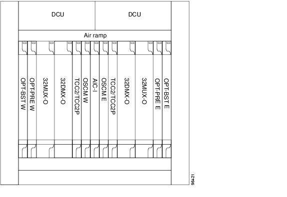
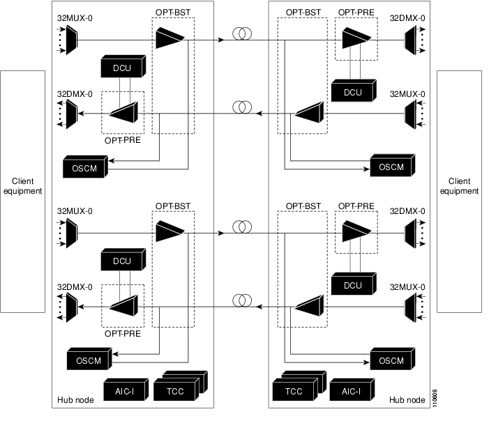
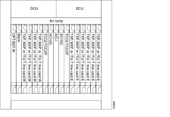
You can install dispersion compensation units (DCUs) in the ONS 15454 dispersion compensation shelf when optical preamplifier cards are installed in the DWDM node. Each DCU module can compensate a maximum of 65 km of single-mode fiber (SMF-28) span. DCUs can be cascaded to extend the compensation to 130 km. Figure 4-1 shows a Hub node configuration with DCU cards installed.
Figure 4-1 Hub Node Configuration with DCU Cards Installed
Power Launched
In a DWDM system, the maximum allowable power per channel launched in the fiber (transmitted power), is the starting point of power calculations to assure that the optical signal at the receiver has enough power to be detected without errors or within a BER objective (e.g. <10-11). The maximum allowable power per channel cannot be arbitrary, because the nonlinear effects increase as coupled power increases. Table 4-7 lists the maximum transmitter output per channel for the ONS 15454 OC48 and OC192 ITU-T cards, with a BER of 10-12.
Optical Amplification
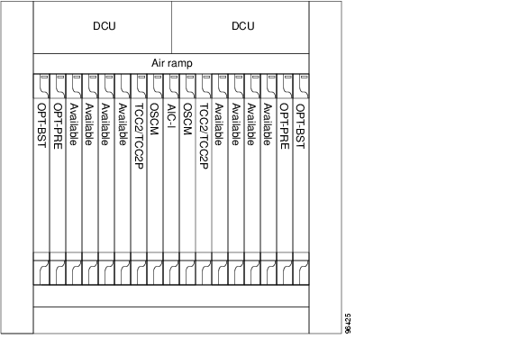
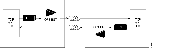
Optical signal losses should be carefully budgeted and EDFAs should be used to boost the power of the optical signal if needed. You should attempt to space your EDFAs at equal distances apart, if possible, to assure the DWDM system is properly balanced. The ONS 15454 MSTP supports two optical EDFA amplifier cards: Preamplifier (OPT-PRE) and Optical Booster (OPT-BST). These cards are used in amplified DWDM nodes, including hub nodes, amplified OADM nodes, and line amplified nodes. If a DCU is not installed, a 5 dB attenuator loop must be installed between the OPT-PRE DC ports. Figure 4-2 shows a Hub node configuration with OPT-PRE and OPT-BST amplifier cards installed.
Figure 4-2 Hub Node Configuration with Amplifier Cards Installed
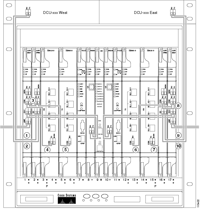
Figure 4-3 shows an example of how to cable a Hub node configured with DCU and amplifier cards.
Figure 4-3 Hub Node Wiring Example
1. West DCU TX to west OPT-PRE DC RX12. West DCU RX to west OPT-PRE DC TX13. West OPT-BST COM TX to west OPTPRE COM RX4. West OPT-BST COM RX to west 32MUXO COM TX5. West OPT-PRE COM TX to west 32DMXO COM RX6. East 32DMX-O COM RX to east OPTPRE COM TX7. East 32MUX-O COM TX to east OPTBSTCOM RX8. East OPT-PRE COM RX to east OPTBST COM TX9. East DCU TX to east OPT-PRE DC RX110. East DCU RX to east OPT-PRE DC TX1The OC48 ITU-T cards have a single channel span budget of 25 dB. If the span loss is greater than 25 dB, amplification may be used to extend the optical reach of the cards. The OC192 ITU-T cards have a single channel span budget of 23 dB. If the span loss is greater than 30 dB, amplification may be used to extend the optical reach of the cards. Table 4-8 specifies the range of attenuation per span using EDFAs.
Fiber Types
Various factors, such as amplifier bandwidth and amplifier spontaneous emission (ASE) limit optical transmission. In addition to linear effects, such as fiber attenuation, chromatic dispersion, and polarization mode dispersion (PMD), there are nonlinear effects related to the refractive index and scattering that degrades system performance.
The contribution of the nonlinear effects to transmission is defined as the optical power density (power/effective area) times the length of the fiber. The effective area is defined as the cross-section of the light path in a fiber. Depending on the type of fiber, the effective area varies between 50 and 72 mm2, the lowest corresponding to dispersion-shifted fiber (DSF) and the highest to single-mode fiber (SMF). The higher the optical power density and the longer the fiber, the more the nonlinear contribution.
For a fixed length of fiber, the only variable that can be manipulated to lower the nonlinear contribution is optical power. However, if the optical power is lowered, the bit rate should be lowered to maintain transmission at the expected BER. Table 4-9 specifies the attenuation and chromatic dispersion for some of the types of optical fibers that have been tested with the ONS 15454 using OC 48 ELR ITU-T cards.
Optical Power Budget
The optical power budget amounts to calculating all signal losses at every component in the optical path (couplers, filters, cross-connects, connectors, splices, multiplex/demultiplex, fiber, optical patch panels, etc.) between the transmitter and receiver. The main objective is to assure that the power of the optical signal at the receiver is greater than the sensitivity of the receiver.
Power gain and loss (in dB) is additive. Start with the power of the optical signal to be launched into the fiber, expressed a 0 dB. Then, for each loss item, the dB loss is subtracted from it, and for optical amplifiers, the gain is added to it. The remaining is compared with the receiver sensitivity. Typically a net power margin of 3 dB or more is desirable. The power budget formula is as follows:
(Margin) = (Transmitter output power) - (Receiver sensitivity) - (S losses dB)
Table 4-10 specifies the optical power of the composite signal with respect to the number of individual channels being multiplexed and demultiplexed by typical passive DWDM filters.
Table 4-10 adopts the standard practice that each channel has the same optical power. It does not take into account insertion loss, however, which must be applied to the table's values. You can typically add 0.3 dB of insertion loss per connector and 0.1 dB of loss per splice. Cisco recommends that you allow a 3 dB optical power design margin and equalize the individual optical signals forming a composite signal.
Metro DWDM Design Example
Typically, a DWDM network design will fall in one of the following categories:
•
•
The following example provides a manual step-by-step approach to designing a Fixed Distance Metro DWDM network using ONS 15454 OC48 200 GHz ITU-T cards and Cisco's 200 GHz passive DWDM products. You can substitute the Cisco's DWDM products and specifications with third party passive DWDM equipment without affecting the steps listed below. For ONS 15454 MSTP Metro Core applications, Cisco recommends designing the DWDM network with MetroPlanner, Release 2.5 or higher. Cisco MetroPlanner prepares a shelf plan for each network node, and calculates the power and attenuation levels for the DWDM cards installed in the node. Cisco MetroPlanner exports the calculated parameters to an ASCII file called "NE Update." In CTC, you can import the NE Update file to automatically provision the node.
Caution
Caution
Note
Step 1: Physical Parameters
Using Figure 4-4 as a reference, identify the general characteristics of the network, which includes the following:
•
•
•
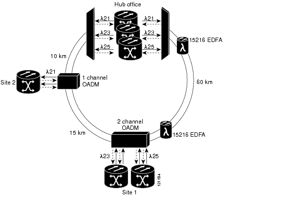
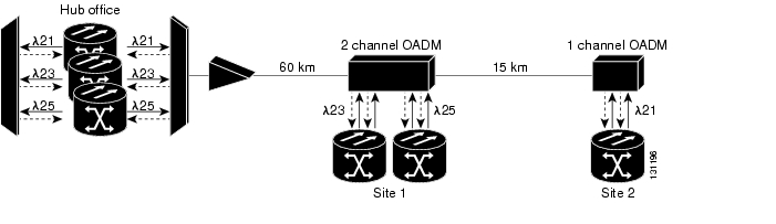
Figure 4-4 DWDM Reference Network
The network is configured in a ring topology. For this example, assume the fiber type is SMF-28 and only 2 fibers are available. There are 3 sites, a Hub and two OADM locations. Network Planning has determined a need for three OC-48 channels, with 1+1 protection, between these locations. All three channels will terminate at the Hub Office. Two channels will be dropped and inserted at Site 1 and one channel will be dropped and inserted at Site 2. Network traffic is forecasted to grow at 3% annually over the next five years.
Complete a table for each working (clockwise) and protect (counter-clockwise) span, such as Table 4-11. Span loss is calculated as follows:
Span loss = fiber length x fiber attenuation
Identify the dispersion characteristics of the optical fiber being used and calculate the maximum fiber path length that would be used without regeneration with the following formula:
Maximum fiber path length = [chromatic dispersion allowance (ps/nm)] / [fiber dispersion (ps/nm/km)]
The chromatic dispersion allowance depends on the characteristics of the source. The fiber dispersion depends on the fiber type, i.e. SMF-28, LEAF, TrueWave, etc. The dispersion for SMF-28 is 18 ps/nm/km and the chromatic dispersion allowance for the ONS 15454 OC48 200 GHz ITU-T optics is 3600 ps/nm. The maximum fiber path length without regeneration for this example is 200 km (3600 ps/nm / 18 ps/nm/km).
Step 2: Channel Plan
Identify the number channels required for the design and select the appropriate ITU-T wavelengths, DWDM filters, and OADMs. Channels are added or dropped at a node in clockwise or counter-clockwise direction, or they are passed directly through the node.
Tip
Channel 21 (1560.61 nm) will be mapped to a 1-Channel OADM unit and Channel 23 (1558.98 nm) and Channel 25 (1557.36 nm) will be mapped to a 2-Channel OADM unit. Channels 23 and 25 are being dropped at Site 1 and Channel 21 is being dropped at Site 2. Multi-channel passive DWDM filters will be used at the Hub Office.
After identifying which channels to use, create a channel plan like the one shown in Table 4-12.
For this example, multiplexing 3 channels at 0 dBm yields a 0.3 dBm composite signal (0 dBm + 4.8 dB - 4.5 dB). Demultiplexing an -8 dBm composite signal into 3 channels gives -17.3 dBm of optical power for each channel (-8.0 dBm - 4.8 dB - 4.5 dB). Table 4-13 shows what happens to single channel power as channels are demultiplexed.
In this example, a composite signal composed of 3 individual optical signals goes through a 1-channel OADM operating at 1560.61 nm. If the power of the composite signal is 0.3 dBm, the power of the 1560.61 nm dropped optical signal is -4.3 dBm (0.3 dBm - 4.8 dB - 2.5 dB). On the other hand, the added 1560.61 nm optical signal has to be manually attenuated by 2.3 dB if coming from a 0 dBm transmitter. With the effect of the add insertion loss, this provides a -6.3 dBm added optical signal which equates for the composite signal going through the throughput path (0.3 dBm - 4.8 dB - 1.8 dB).
Step 3: Regeneration Verification
For each path, the fiber length should be compared to the maximum length calculated in Step 1 to determine whether a regeneration site is needed. If regeneration is needed, the two resulting spans (to and from the regeneration site) should be treated independently. None of the paths exceed the 200 km maximum length calculated in Step 1. Therefore, no regeneration site is required for this example.
Step 4: Channel/Wavelength Selection
The data from the Table 4-12 in Step 2 is used to select the OC48 200 GHz ITU-T cards. For this example, wavelengths 1560.61 nm, 1558.98 nm, and 1557.36 nm were selected. For 1+1 protection, six OC48 200 GHz ITU-T optics cards are required for the Hub Office, four are required for Site 1, and two are required at Site 2.
Step 5: Calculate Path Loss
Calculate the total working path and total protect path losses, based on the type of DWDM filter or OADM used. The formula for total path loss is as follows:
Total Path Loss = (Fiber Loss) + (# of DWDM filters x 4.5 dB) + (# of 1-channel OADMs x 1.8 dB) + (# of 2-channel OADMs x 2.0 dB)
Fiber Loss = Fiber Attenuation x Span Length
The total path loss for each clockwise and counter clockwise span is shown in Table 4-14.
Step 6: Amplification
If the total path loss exceeds 22 dB in any channel path, an amplification solution is required. Amplifiers work with total power where Pin + Pgain = Pout. For multi-wavelengths, total power is summed as Pin=
. In choosing which location to place the EDFAs, identify a reference node. This should be the source node of the channel, because that should have the lowest power level. For this design, the Hub Office is the reference node.
Work from the reference node in one direction, place the first EDFA at the position where there is a loss of 19 dB or the measured power level is -19 dBm per channel. If the -19 dB point is at a midspan position, check the power level at the input of the next node. If this power level is above -22 dBm, the EDFA can be positioned at the next node. Otherwise it should be placed at the preceding node with an attenuator at the input to avoid exceeding the amplifier maximum input power. The attenuator should bring the EDFA input power to -19 dBm. For OADM nodes, it is preferable to place the EDFA after the node instead of before it, because this will make it easier to carry out the channel power equalization for the added channels on that node. If the EDFA is placed before an OADM node, check that the added power can be adjusted to the power level of the pass-through channel.
Because the total loss for the Hub Office to Site 1 working path and Site 1 to Hub Office protect path exceed 22 dB, each of those spans will require an EDFA.
After placing the first EDFA, recalculate the power levels and place the second EDFA where the power level reaches -19 dBm again. To avoid an unexpected OSNR level, place subsequent EDFAs as close as possible to the -19 dBm power level. If the EDFA power is above -19 dBm, it should be attenuated to -19 dBm. Repeat this process for all remaining amplifiers and then repeat this process in the reverse direction.
The gain and OSNR guidelines for the EDFA used in this example are shown in Table 4-15.
For a single optical amplifier between transmitter and receiver, use the value from Table 4-15. For multi-stage optical amplifiers use the following formula:
SNRout = 1/(1/SNRin + FhfB/Pin) where:
•
•
•
•
•
•
•
•
Step 7: Attenuation
After placing all of the EDFAs, the channel powers around the network should be calculated again based on a 0dBm input signal and for all add/drop nodes the power levels of the dropped signal and added signal should be calculated. The dropped power level is:
Pdropped = Node input power - dropped channel insertion loss
For example, if the power level into an 1-channel OADM is -13 dBm and the dropped channel insertion loss is 2.1 dB, then the dropped channel power will be -15.1 dBm (-13 dBm - 2.1 dB).
If the calculated dropped power is above -15 dBm an appropriate attenuator should be used for those dropped channels to adjust the power level to the -15 dBm level and avoid the overload risk on the receiver for those channels. The added power level is:
Padded = Node output power + add channel insertion loss
For example, if the power level out of a 1-Channel OADM is -13 dBm and the added channel insertion loss is 3.2 dB then the added channel's power level to the add point should be -9.8 dBm (-13 dBm + 3.2 dB).
To achieve these add channel power levels, use a VOA (if available) or external attenuators for the OADMs and DWDM filters.
Step 8: Final Design Verification
The final verification of the network is carried out by propagating 9 dBm power from the reference node (Hub Office) and checking whether the power returned back to the same point is 0 dBm as well. Take the following points into consideration when making this verification:
•
•
•
The per channel calculations for the design example are shown below.
Fiber Characteristics:
•
•
Multiplex/Demultiplex Characteristics:
•
•
•
2-Channel OADM Characteristics:
•
•
•
•
1-Channel OADM Characteristics:
•
•
•
•
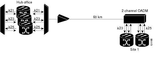
From the Hub Office to Site 1 (see Figure 4-5) the following calculations apply:
Figure 4-5 Hub Office to Site 1
-2.0 dBm ELR Output
+4.5 dB Mux insertion loss
+4.8 dB Conversion to Composite power
-1.7 dBm Composite power into the EDFA
-4.3 dB VOA added to meet the minimum EDFA input specification
-6.0 dbm Composite power into the EDFA
+23 dB Gain from the EDFA2
+17.0 dBm Composite power out of the EDFA
-18.0 dB For 60 km of span loss
-2.6 dBm Drop loss for the 2-Channel OADM
-4.8 dB Conversion to Channel power
-8.4 dB at the OC48 ITU-T receiver at Site 1
The per channel calculations from the Hub Office to Site 2 (see Figure 4-6) are as follows:
Figure 4-6 Hub Office to Site 2
For the pass-through channel power @ site 1: (-5.8 - 2) = -7.8 dBm
-7.8 dBm out of 2-Channel OADM
-4.5 dB For 15 km of span loss
-2.1 dB Drop loss for the 1-Channel OADM
-14.4 dBm at the OC4 ITU-T receiver of Site 2
The passthrough channel power at Site 2: (-12.3 - 1.8) = -13.1 dBm
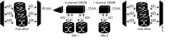
The per channel calculations from Hub Office to Hub Office (see Figure 4-7) are as follows:
Figure 4-7 Hub Office to Hub Office
-13.1 dBm out of OADM-1
-4.5 dB For 15 km of span loss
-4.5 dB Drop loss for the Demux
-22.1 dBm at the OC48 ITU-T receiver of the Hub Office
Counter clockwise (protection) calculations are shown below.
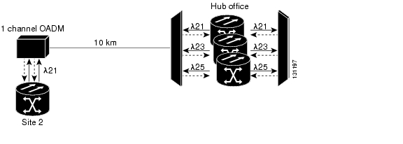
The per channel calculations from the Hub Office to Site 2 (see Figure 4-8) are as follows:
Figure 4-8 Hub Office to Site 2
-2.0 dBm ELR Output
-4.5 dB Mux insertion loss
-6.5 dBm Composite power
-3.0 dB for 10 km of span loss
-2.1 dBm Drop loss for the 1-Channel OADM
-11.6 dB at the OC48 ITU-T receiver at Site 2
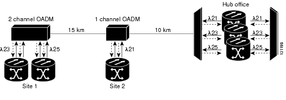
The per channel calculations from the Hub Office to Site 1 (see Figure 4-9) are as follows:
Figure 4-9 Hub Office to Site 1
For the pass thru channel power @ site 2: (-9.5 - 1.8) = -11.3 dBm
-11.6 dBm out of the 1-Channel OADM
-4.5 dB for 15 km of span loss
-2.6 dBm Drop loss for the 2-Channel OADM
-18.7 dB at the OC48 ITU-T receiver of Site 1
The per channel calculations from Hub Office to Hub Office (see Figure 4-10) are as follows:
Figure 4-10 Hub Office to Site 1
For the pass thru channel power at Site 1: (-16.1 - 2) = -18.1 dBm
-18.1 dBm out of the 2-Channel OADM
+22 dB Gain from the EDFA
+3.9 dBm Channel power out of the EDFA
-18.0 dB For 60 km of span loss
-4.5 dB Insertion loss of the Passive DWDM filter
-18.6 dBm at the OC48 ITU-T receiver of the Hub Office
DWDM Card Reference
The following common control cards are needed to support the functions of the DWDM, transponder, and muxponder cards:
•
•
DWDM Cards
Each DWDM card is marked with a symbol that corresponds to a slot (or slots) on the ONS 15454 shelf assembly. These cards can only be installed into slots displaying the same symbols.
ONS 15454 DWDM cards are grouped into the following categories:
•
•
•
•
•
•
–
–
Table 4-16 describes the Cisco ONS 15454 DWDM cards available for MSTP applications.
Table 4-16 ONS 15454 DWDM Cards
Optical Service Channel Modules
OSCM
15454-OSCM=
The OSCM has one set of optical ports and one Ethernet port located on the faceplate. It operates in Slots 8 and 10.
An optical service channel (OSC) is a bidirectional channel connecting all the nodes in a ring. The channel transports OSC overhead that is used to manage ONS 15454 DWDM networks. The OSC uses the 1510 nm wavelength and does not affect client traffic. The primary purpose of this channel is to carry clock synchronization and orderwire channel communications for the DWDM network. It also provides transparent links between each node in the network. The OSC is an OC-3 formatted signal.
The OSCM is used in amplified nodes that include the OPT-BST booster amplifier. The OPT-BST includes the required OSC wavelength combiner and separator component. The OSCM cannot be used in nodes where you use OC-N cards, electrical cards, or cross-connect cards. The OSCM uses slots 8 and 10 when the ONS 15454 is configured as an MSTP.
OSC-CSM
15454-OSC-CSM=
The OSC-CSM has three sets of optical ports and one Ethernet port located on the faceplate. It operates in Slots 1 to 6 and 12 to 17.
The OSC-CSM is identical to the OSCM, but also contains a combiner and separator module in addition to the OSC module.
The OSC-CSM is used in unamplified nodes. This means that the booster amplifier with the OSC wavelength combiner and separator is not required for OSC-CSM operation. The OSC-CSM can be installed in slots 1 to 6 and 12 to 17 when the ONS 15454 is configured as an MSTP.
Optical Amplifiers
OPT-PRE
15454-OPT-PRE=
The OPT-PRE is designed to support 64 channels at 50-GHz channel spacing, but Software R4.6 only supports 32 channels at 100 GHz. The OPT-PRE is a C-band DWDM, two-stage erbium-doped fiber amplifier (EDFA) with mid-amplifier loss (MAL) for allocation to a dispersion compensation unit (DCU). To control the gain tilt, the OPT-PRE is equipped with a built-in VOA. The VOA can also be used to pad the DCU to a reference value. You can install the OPT-PRE in slots 1 to 6 and 12 to 17 when the ONS 15454 is configured as an MSTP.
OPT-BST
15454-OPT-BST=
The OPT-BST is designed to support 64 channels at 50-GHz channel spacing, but Software R4.6 supports 32 channels at 100 GHz. The OPT-BST is a C-band DWDM EDFA with OSC add-and-drop capability. When an ONS 15454 MSTP has an OPT-BST installed, it is only necessary to have the OSCM to process the OSC. To control the gain tilt, the OPT-BST is equipped with a built-in VOA. You can install the OPT-BST in slots 1 to 6 and 12 to 17 when the ONS 15454 is configured as an MSTP.
Multiplexer and Demultiplexer Cards
32MUX-O
15454-32MUX-O=
The 32-channel multiplexer card (32 MUX-O) multiplexes 32 100 GHz-spaced channels identified in the channel plan. The 32 MUX-O card takes up two slots in an ONS 15454 MSTP and can be installed in slots 1 to 5 and 12 to 16.
32DMX-O
15454-32DMX-O=
The 32-Channel Demultiplexer (32 DMX-O) card demultiplexes 32 100 GHz-spaced channels identified in the channel plan. The 32 DMX-O takes up two slots in an ONS 15454 MSTP and can be installed in slots 1 to 5 and 12 to 16.
32DMX
15454-32DMX=
The 32-Channel Demultiplexer card (32DMX) is a single-slot optical demultiplexer. The card receives an aggregate optical signal on its COM RX port and demultiplexes it into to 32 100-GHz-spaced channels. The 32DMX card can be installed in Slots 1 to 6 and in Slots 12 to 17.
4MD-xx.x
15454-4MD-xx.x=
The 4-Channel Multiplexer/Demultiplexer (4MD-xx.x) card multiplexes and demultiplexes four 100 GHz-spaced channels identified in the channel plan. The 4MD-xx.x card is designed to be used with band OADMs (both AD-1B-xx.x and AD-4B-xx.x). There are eight versions of this card that correspond with the eight sub-bands specified in Table 4-17. The 4MD-xx.x can be installed in slots 1 to 6 and 12 to 17 when the ONS 15454 is configured as an MSTP.
Optical Add/Drop Multiplexer Cards
AD-1C-xx.x
15454-AD-1C-xx.x=
The 1-Channel OADM (AD-1C-xx.x) card passively adds or drops one of the 32 channels utilized within the 100 GHz-spacing of the DWDM card system. There are thirty-two versions of this card, each designed only for use with one wavelength. Each wavelength version of the card has a different part number. The AD-1C-xx.x can be installed in slots 1 to 6 and 12 to 17 when the ONS 15454 is configured as an MSTP.
AD-2C-xx.x
15454-AD-2C-xx.x=
The 2-Channel OADM (AD-2C-xx.x) card passively adds or drops two adjacent 100 GHz channels within the same band. There are sixteen versions of this card, each designed for use with one pair of wavelengths. The card bidirectionally adds and drops in two different sections on the same card to manage signal flow in both directions. Each version of the card has a different part number. The AD-2C-xx.x cards are provisioned for the channel pairs in Table 4-18. In this table, channel IDs are given rather than wavelengths. The AD-2C-xx.x can be installed in slots 1 to 6 and 12 to 17 when the ONS 15454 is configured as an MSTP.
AD-4C-xx.x
15454-AD-4C-xx.x=
The 4-Channel OADM (AD-4C-xx.x) card passively adds or drops all four 100 GHz-spaced channels within the same band. There are eight versions of this card, each designed for use with one band of wavelengths. The card bidirectionally adds and drops in two different sections on the same card to manage signal flow in both directions. There are eight versions of this card with eight part numbers. The AD-4C-xx.x cards are provisioned for the channel pairs in Table 4-19. In this table, channel IDs are given rather than wavelengths. The AD-4C-xx.x can be installed in slots 1 to 6 and 12 to 17 when the ONS 15454 is configured as an MSTP.
AD-1B-xx.x
15454-AD-1B-xx=
The 1-Band OADM (AD-1B-xx.x) card passively adds or drops a single band of four adjacent 100 GHz-spaced channels. There are eight versions of this card with eight different part numbers, each version designed for use with one band of wavelengths. The card bidirectionally adds and drops in two different sections on the same card to manage signal flow in both directions. This card can be used when there is asymmetric adding and dropping on each side (east or west) of the node; a band can be added or dropped on one side but not on the other. The AD-1B-xx.x can be installed in slots 1 to 6 and 12 to17 when the ONS 15454 is configured as an MSTP.
AD-4B-xx.x
15454-AD-4B-xx=
The 4-Band OADM (AD-4B-xx.x) card passively adds or drops four bands of four adjacent 100 GHz-spaced channels. There are two versions of this card with different part numbers, each version designed for use with one set of bands. The card bidirectionally adds and drops in two different sections on the same card to manage signal flow in both directions. This card can be used when there is asymmetric adding and dropping on each side (east or west) of the node; a band can be added or dropped on one side but not on the other. The AD-4B-xx.x cards are provisioned for the channel pairs in Table 4-20. In this table, channel IDs are given rather than wavelengths. The AD1B-xx.x can be installed in slots 1 to 6 and 12 to 17 when the ONS 15454 is configured as an MSTP.
32WSS
15454-32WSS=
The 32WSS card has seven sets of ports located on the faceplate. The card takes up two slots and can operates in Slots 1-2, 3-4, 5-6, or in Slots 12-13, 14-15, or 16-17.
The 32-Channel Wavelength Selective Switch (32WSS) card performs channel add/drop processing within the ONS 15454 DWDM node. The 32WSS works in conjunction with the 32DMX to implement ROADM functionality. Equipped with ROADM functionality, the ONS 15454 DWDM can be configured to add or drop individual optical channels using CTC, Cisco MetroPlanner, and CTM.
A ROADM network element utilizes two 32WSS cards (two slots each) and two 32DMX cards (one slot each), for a total of six slots in the chassis.
Transponder and Muxponder Cards
TXP_MR_10G
15454-10T-L1-30.3=
15454-10T-L1-31.9=
15454-10T-L1-34.2=
15454-10T-L1-35.8=
15454-10T-L1-38.1=
15454-10T-L1-39.7=
15454-10T-L1-42.1=
15454-10T-L1-43.7=
15454-10T-L1-46.1=
15454-10T-L1-47.7=
15454-10T-L1-50.1=
15454-10T-L1-51.7=
15454-10T-L1-54.1=
15454-10T-L1-55.7=
15454-10T-L1-58.1=
15454-10T-L1-59.7=
The TXP_MR_10G card has two sets of ports located on the faceplate and can be in Slots 1 to 6 and 12 to 17.
The 10 Gbps Transponder-100 GHz-Tunable xx.xx-xx.xx card (TXP_MR_10G) processes one 10 Gb/s signal (client side) into one 10-Gb/s, 100 GHz DWDM signal (trunk side). It provides one 10 Gb/s port per card that can be provisioned for an STM64/OC-192 short reach (1310nm) signal, compliant with ITU-T G.707, G.709, ITU-T G.691, Telcordia GR-253-CORE, or to 10 GE BASE-LR, compliant to IEEE 802.3.
The TXP_MR_10G card is tunable over two neighboring wavelengths in the 1550nm, ITU 100 GHz range. It is available in sixteen different versions, covering thirty-two different wavelengths in the 1550nm range.
TXP_MR_10E
15454-10E-L1-30.3=
15454-10E-L1-34.2=
15454-10E-L1-38.1=
15454-10E-L1-42.1=
15454-10E-L1-46.1=
15454-10E-L1-50.1=
15454-10E-L1-54.1=
15454-10E-L1-58.1=
The TXP_MR_10E card has two sets of ports located on the faceplate and can be installed in Slots 1 to 6 and Slots 12 to 17.
The 10 Gb/s Transponder-100 GHz-Tunable xx.xx-xx.xx (TXP_MR_10E) card is a multirate transponder for the ONS 15454 platform. It processes one 10 Gb/s signal (client side) into one 10 Gb/s, 100 GHz DWDM signal (trunk side) that is tunable on four wavelength channels (ITU-T 100 GHz grid).
You can provision this card in a linear configuration, BLSR, path protection, or a regenerator. The card can be used in the middle of BLSR or 1+1 spans when the card is configured for transparent termination mode.
The TXP_MR_10E port features a 1550nm laser for the trunk port and an ONS-XC-10G-S1 XFP module for the client port and contains two transmit and receive connector pairs (labeled) on the card faceplate.
The TXP_MR_10E card is tunable over four wavelengths in the 1550nm ITU 100-GHz range. They are available in eight versions of the card, covering thirty-two different wavelengths in the 1550nm range
TXP_MR_2.5G
15454-MR-L1-30.3=
15454-MR-L1-34.2=
15454-MR-L1-38.1=
15454-MR-L1-42.1=
15454-MR-L1-46.1=
15454-MR-L1-50.1=
15454-MR-L1-54.1=
15454-MR-L1-58.1=
The TXP_MR_2.5G card has two sets of ports located on the faceplate and can be installed in Slots 1 to 6 and Slots 12 to 17.
The 2.5 Gb/s Multirate Transponder-100 GHz-Tunable xx.xx-xx.xx (TXP_MR_2.5G) card processes one 8 Mb/s to 2.488 Gb/s signal (client side) into one 8 Mb/s to 2.5 Gb/s, 100 GHz DWDM signal (trunk side). It provides one long-reach STM-16/OC-48 port per card, compliant with ITU-T G.707, ITU-T G.709, ITU-T G.957, and Telcordia GR-253-CORE.
The TXP_MR_2.5G card is tunable over four wavelengths in the 1550nm ITU 100-GHz range. They are available in eight versions of the card, covering thirty-two different wavelengths in the 1550nm range.
The TXP_MR_2.5G card support 2R and 3R modes of operation where the client signal is mapped into a ITU-T G.709 frame.
TXPP_MR_2.5G
15454-MRP-L1-30.3=
15454-MRP-L1-34.2=
15454-MRP-L1-38.1=
15454-MRP-L1-42.1=
15454-MRP-L1-46.1=
15454-MRP-L1-50.1=
15454-MRP-L1-54.1=
15454-MRP-L1-58.1=
The TXPP_MR_2.5G card has three sets of ports located on the faceplate and can be installed in Slots 1 to 6 and Slots 12 to 17.
The 2.5 Gb/s Multirate Transponder-Protected-100 GHz-Tunable xx.xxxx. xx (TXPP_MR_2.5G) card processes one 8 Mb/s to 2.488 Gb/s signal (client side) into two 8 Mb/s to 2.5 Gb/s, 100 GHz DWDM signals (trunk side). It provides two long-reach STM-16/OC-48 ports per card, compliant with ITU-T G.707, ITU-T G.957, and Telcordia GR-253-CORE.
The TXPP_MR_2.5G card is tunable over four wavelengths in the 1550nm ITU 100-GHz range. They are available in eight versions of the card, covering thirty-two different wavelengths in the 1550nm range.
The TXPP_MR_2.5G card support 2R and 3R modes of operation where the client signal is mapped into a ITU-T G.709 frame.
MXP_2.5G_10G
15454-10M-L1-30.3=
15454-10M-L1-31.9=
15454-10M-L1-34.2=
15454-10M-L1-35.8=
15454-10M-L1-38.1=
15454-10M-L1-39.7=
15454-10M-L1-42.1=
15454-10M-L1-43.7=
15454-10M-L1-46.1=
15454-10M-L1-47.7=
15454-10M-L1-50.1=
15454-10M-L1-51.7=
15454-10M-L1-54.1=
15454-10M-L1-55.7=
15454-10M-L1-58.1=
15454-10M-L1-59.7=
The MXP_2.5G_10G card has 9 sets of ports located on the faceplate and can be installed in Slots 1 to 6 and Slots 12 to 17.
The 2.5 Gb/s-10 Gb/s Muxponder-100 GHz-Tunable xx.xx-xx.xx (MXP_2.5G_10G) card multiplexes/demultiplexes four 2.5 Gb/s signals (client side) into one 10 Gb/s, 100 GHz DWDM signal (trunk side). It provides one extended long-range STM-64/OC-192 port per card on the trunk side (compliant with ITU-T G.707, ITU-T G.709, ITU-T G.957, and Telcordia GR-253-CORE) and four intermediate- or short-range OC-48/STM-16 ports per card on the client side. The port operates at 9.95328 Gb/s over unamplified distances up to 80 km (50 miles) with different types of fiber such as C-SMF or dispersion compensated fiber limited by loss and/or dispersion. The port can also operate at 10.70923 Gb/s in ITU-T G.709 Digital Wrapper/FEC mode.
Client ports on the MXP_2.5G_10G card are also interoperable with OC-1 (STS-1) fiber optic signals defined in Telcordia GR-253-CORE. An OC-1 signal is the equivalent of one DS3 channel transmitted across optical fiber. OC-1 is primarily used for trunk interfaces to phone switches in the United States.
The MXP_2.5G_10G card is tunable over two neighboring wavelengths in the 1550nm, ITU 100 GHz range. It is available in sixteen different versions, covering thirty-two different wavelengths in the 1550nm range.
MXP_2.5G_10E
15454-10ME-30.3=
15454-10ME-34.2=
15454-10ME-38.1=
15454-10ME-42.1=
15454-10ME-46.1=
15454-10ME-50.1=
15454-10ME-54.1=
15454-10ME-58.1=
The MXP_2.5G_10E card has 9 sets of ports located on the faceplate and can be installed in Slots 1 to 6 and 12 to 17.
The 2.5 Gb/s-10 Gb/s Muxponder-100 GHz-Tunable xx.xx-xx.xx (MXP_2.5G_10E) card is a DWDM muxponder for the ONS 15454 platform that supports full optical transparency on the client side. The card multiplexes four 2.5 Gb/s client signals (4 x OC48/STM-16 SFP) into a single 10 Gb/s DWDM optical signal on the trunk side. The MXP_2.5G_10E provides wavelength transmission service for the four incoming 2.5 Gbps client interfaces. The MXP_2.5G_10E muxponder passes all SONET overhead bytes transparently.
The MXP_2.5G_10E works with Optical Transparent Network (OTN) devices defined in ITU-T G.709. The card supports Optical Data Channel Unit 1 (ODU1) to Optical Channel Transport Unit (OTU2) multiplexing, an industry standard method for asynchronously mapping a SONET/SDH payload into a digitally wrapped envelope.
The MXP_2.5G_10E card is tunable over four neighboring wavelengths in the 1550nm, ITU 100 GHz range. It is available in eight different versions, covering thirty-two different wavelengths in the 1550nm range.
The MXP_2.5G_10E card is not compatible with the MXP_2.5G_10G card, which does not supports full optical transparency. The faceplate designation of the card is "4x2.5G 10E MXP."
MXP_MR_2.5G
15454-DM-L1-30.3=
15454-DM-L1-34.2=
15454-DM-L1-38.1=
15454-DM-L1-42.1=
15454-DM-L1-46.1=
15454-DM-L1-50.1=
15454-DM-L1-54.1=
15454-DM-L1-58.1=
The MXP_MR_2.5G card has 9 sets of ports located on the faceplate and can be installed in Slots 1 to 6 and Slots 12 to 17.
The 2.5 Gb/s Multirate Muxponder-100 GHz-Tunable 15xx.xx-15yy.yy (MXP_MR_2.5G) card aggregates a mix and match of client Storage Area Network (SAN) service client inputs (GE, FICON, and Fibre Channel) into one 2.5 Gb/s STM-16/OC-48 DWDM signal on the trunk side. It provides one long-reach STM-16/OC-48 port per card and is compliant with Telcordia GR-253-CORE.
The client interface supports the following payload types:
•
•
•
•
•
Because the card is tunable to one of four adjacent grid channels on a 100 GHz spacing, this card is available in eight versions covering thirty-two different wavelengths in the 1550nm range.
MXPP_MR_2.5G
15454-DMP-L1-30.3=
15454-DMP-L1-34.2=
15454-DMP-L1-38.1=
15454-DMP-L1-42.1=
15454-DMP-L1-46.1=
15454-DMP-L1-50.1=
15454-DMP-L1-54.1=
15454-DMP-L1-58.1=
The MXPP_MR_2.5G card has 10 sets of ports located on the faceplate and can be installed in Slots 1 to 6 and Slots 12 to 17.
The 2.5 Gb/s Multirate Muxponder-Protected-100 GHz-Tunable 15xx.xx- 15yy.yy (MXPP_MR_2.5G) card aggregates various client SAN service client inputs (GE, FICON, and Fibre Channel) into one 2.5 Gb/s STM-16/OC-48 DWDM signal on the trunk side. It provides two long-reach STM-16/OC-48 ports per card and is compliant with ITU-T G.957 and Telcordia GR-253-CORE.
The client interface supports the following payload types:
•
•
•
•
•
Because the card is tunable to one of four adjacent grid channels on a 100 GHz spacing, this card is available in eight versions covering thirty-two different wavelengths in the 1550nm range.
Table 4-17 shows the band IDs and the add/drop channel IDs for the 4MD-xx.x card.
Multiplexer, Demultiplexer, and OADM Card Interface Classes
The 32MUX-O, 32WSS, 32DMX, 32DMX-O, 4MD-xx.x, AD-1C-xx.x, AD-2C-xx.x, and AD-4C-xx.x cards have different input and output power values depending upon the optical power of the interface card where the input signal originates. The client interfaces for these cards have been grouped in classes listed in Table 4-21. The subsequent tables list the optical performances and output power of each interface class.
10 Gbps cards that provide signal input to OADM cards have the optical performances listed in Table 4-22.
Table 4-22 10 Gbps Interface Optical Performances
Type
Power Limited
OSNR Limited
Power Limited
OSNR Limited
OSNR Limited
Power Limited
OSNR Limited
Optical signal to noise ratio (OSNR) sensitivity
23 dB
9 dB
23 dB
19 dB
19 dB
20 dB
8 dB
Power sensitivity
-24 dBm
-18 dBm
-20 dBm
-20 dBm
-22 dBm
-26 dBm
-18 dBm
Dispersion power penalty
2 dB
0 dB
3 dB
4 dB
2 dB
2 dB
0 dB
Dispersion OSNR penalty
0 dB
2 dB
0 dB
0 dB
0 dB
0 dB
2 dB
Dispersion compensation tolerance
+/- 800 ps/nm
+/- 1000 ps/nm
+/- 1000 ps/nm
+/- 800 ps/nm
Maximum bit rate
10 Gb/s
10 Gb/s
10 Gbps
10 Gbps
Regeneration
3R1
3R
3R
3R
FEC
Yes
No
No
Yes (E0FEC)
Threshold
Optimum
Average
Average
Optimum
Maximum BER2
10-15
10-12
10-12
10-15
Power overload
-8 dBm
-8 dBm
-9 dBm
-9 dBm
-8 dBm
Transmitted power range3
10 Gb/s multirate Transponder with FEC (TXP_MR_10G)
+2.5 to 3.5 dBm
+2.5 to 3.5 dBm
—
—
OC-192 LR ITU
—
—
+3.0 to 6.0 dBm
—
10 Gb/s multirate Transponder with FEC (TXP_MR_10E)
+3.0 to 6.0 dBm
+3.0 to 6.0 dBm
+3.0 to 6.0 dBm
1 3R = retime, reshape, regenerate
2 BER = biter error rate
3 These values, decreased by patch cord and connector losses, are also the input power values for the OADM cards.
Table 4-23 2.5 Gb/s Interface Optical Performances—Part One
Optical signal to noise ratio (OSNR) sensitivity
14 dB
6 dB
14 dB
10 dB
15 dB
14 dB
11 dB
Power sensitivity
-31 dBm
-25 dBm
-30 dBm
-23 dBm
-24 dBm
-27 dBm
-33 dBm
Dispersion power penalty
2 dB
0 dB
3 dB
4 dB
3 dB
2 dB
Dispersion OSNR penalty
0 dB
2 dB
0 dB
2 dB
0 dB
0 dB
0 dB
Dispersion compensation tolerance
-1,200 to +5,400 ps/nm
-1,200 to +5,400 ps/nm
-1,200 to +3,300 ps/nm
-1,200 to +3,300 ps/nm
Maximum bit rate
2.5 Gb/s
2.5 Gb/s
2.5 Gb/s
2.5 Gb/s
Regeneration
3R1
3R
2R2
3R
FEC
Yes
No
No
No
Threshold
Average
Average
Average
Average
Maximum BER3
10-15
10-12
10-12
10-12
Power overload
-9 dBm
-9 dBm
-9 dBm
-9 dBm
Transmitted power range4
TXP_MR_2.5G
-1.0 to 1.0 dBm
-1.0 to 1.0 dBm
1.0 to 1.0 dBm
-2.0 to 0 dBm
TXPP_MR_2.5G
-4.5 to -2.5 dBm
-4.5 to -2.5 dBm
-4.5 to -2.5 dBm
-2.0 to 0 dBm
MXP_MR_2.5G
—
+2.0 to +4.0 dBm
—
-2.0 to 0 dBm
MXPP_MR_2.5G
—
-1.5 to +0.5 dBm
—
-2.0 to 0 dBm
1 3R = retime, reshape, regenerate
2 2R = reshape and regenerate
3 BER = biter error rate
4 These values, decreased by patch cord and connector losses, are also the input power values for the OADM cards.
2.5 Gbps card interface performances are listed in Table 4-23 and Table 4-24.
Table 4-24 2.5 Gbps Interface Optical Performances—Part Two
Optical signal to noise ratio (OSNR) sensitivity
13 dB
8 dB
12 dB
Power sensitivity
-28 dBm
-18 dBm
12 dBm
Dispersion compensation tolerance
-1,000 to +3,600 ps/nm
-1,000 to +3,200 ps/nm
Maximum bit rate
1.25 Gbps
2.5 Gbps
Regeneration
3R
3R
FEC
No
No
Threshold
Average
Average
Maximum BER
10-12
10-12
Power overload
-7 dBm
-17 dBm
Transmitted power range1
2 and 4 port GE Transponder (GBIC WDM 100 GHz)
+2.5 to 3.5 dBm
—
1 These values, decreased by patch cord and connector losses, are also the input power values for the OADM cards.
DWDM Node Configurations
The ONS 15454 supports the following DWDM node configurations:
•
•
•
•
•
•
•
Note
Hub Node
A hub node is a single ONS 15454 node equipped with two TCC2/TCC2P cards and one of the following combinations:
•
•
Note
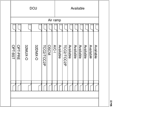
A dispersion compensation unit (DCU) can also be added, if necessary. The hub node does not support both DWDM and TDM applications since the DWDM slot requirements do not leave room for TDM cards. Figure 4-11 shows a hub node configuration with the 32MUX-O and 32DMX-O cards installed.
Note
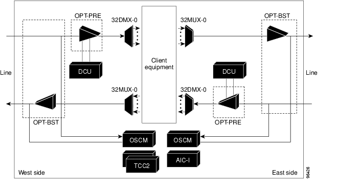
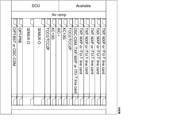
Figure 4-11 Hub Node Configuration Example
Figure 4-12 shows the channel flow for a hub node. Up to 32-channels from the client ports are multiplexed and equalized onto one fiber using the 32MUX-O card. Then, multiplexed channels are transmitted on the line in the eastward direction and fed to the Optical Booster (OPT-BST) amplifier. The output of this amplifier is combined with an output signal from the optical service channel modem (OSCM) card, and transmitted toward the east line.
Received signals from the east line port are split between the OSCM card and an Optical Preamplifier (OPT-PRE). Dispersion compensation is applied to the signal received by the OPTPRE amplifier, and it is then sent to the 32DMX-O card, which demultiplexes and attenuates the input signal. The west receive fiber path is identical through the west OPT-BST amplifier, the west OPT-PRE amplifier, and the west 32DMX-O card.
Figure 4-12 Hub Node Channel Flow Example
Terminal Node
A terminal node is a single ONS 15454 node equipped with two TCC2/TCC2P cards and one of the following combinations:
•
•
Terminal nodes can be either east or west. In west terminal nodes, the cards are installed in the east slots (Slots 1 through 6). In east terminal nodes, cards are installed in the west slots (Slots 12 through 17). A hub node can be changed into a terminal node by removing either the east or west cards. Figure 4-13 shows an example of an east terminal configuration with a 32MUX-O and 32DMX-O cards installed. The channel flow for a terminal node is the same as the hub node (see Figure 4-12).
Note
Figure 4-13 Terminal Node Configuration Example
OADM Node
An OADM node is a single ONS 15454 node equipped with at least one AD-xC-xx.x card or one AD-xB-xx.x card and two TCC2/TCC2P cards. The 32MUX-O or 32DMX-O cards cannot be provisioned. In an OADM node, channels can be added or dropped independently from each direction, passed through the reflected bands of all OADMs in the DWDM node (called express path), or passed through one OADM card to another OADM card without using a TDM ITU line card (called optical pass through) if an external patchcord is installed.
Unlike express path, an optical pass-through channel can be converted later to an add/drop channel in an altered ring without affecting another channel. OADM amplifier placement and required card placement is determined by the MetroPlanner tool or your site plan.
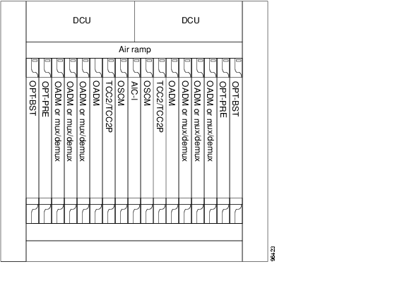
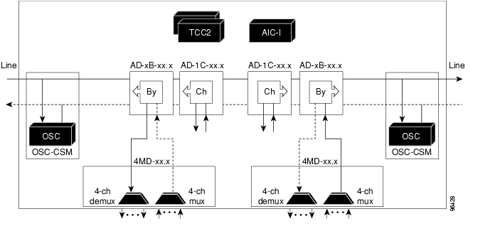
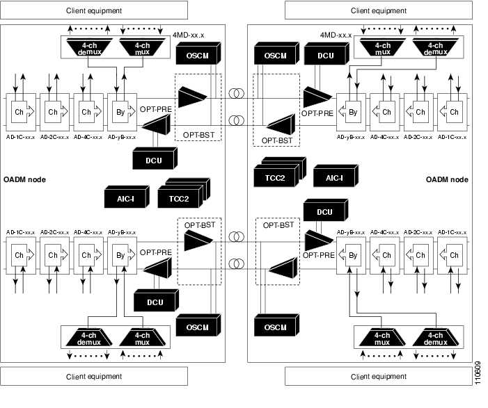
There are different categories of OADM nodes, such as amplified, passive, and anti-ASE. For anti-ASE node information, see the "Anti-ASE Node" section in this chapter. Figure 4-14 shows an example of an amplified OADM node configuration.
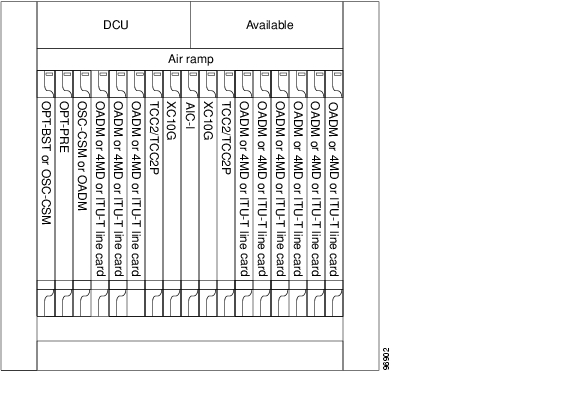
Figure 4-14 OADM Node Configuration Example
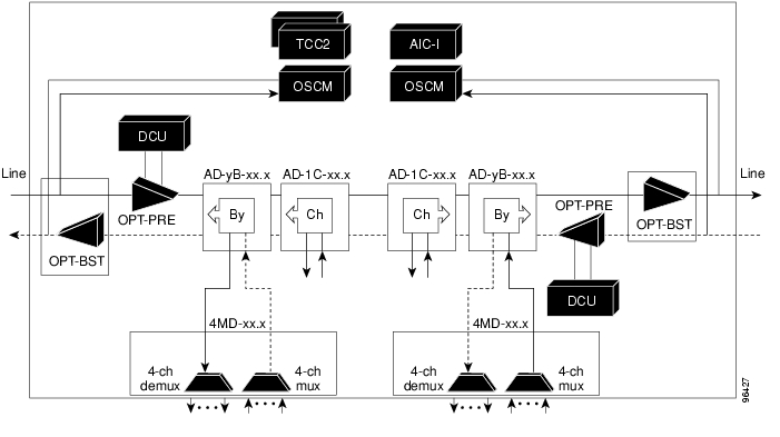
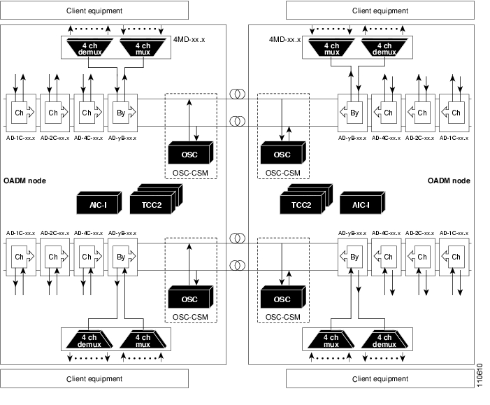
Figure 4-15 shows an example of the channel flow on the amplified OADM node. Since the 32-wavelength plan is based on eight bands (each band contains four channels), optical adding and dropping can be performed at the band level and/or at the channel level (meaning individual channels can be dropped).
Figure 4-15 Amplified OADM Node Channel Flow Example
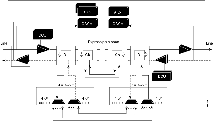
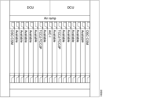
Figure 4-16 shows an example of a passive OADM node configuration. The passive OADM node is equipped with a band filter, one four-channel multiplexer/demultiplexer, and a channel filter on each side of the node.
Figure 4-16 Passive OADM Node Configuration Example
Figure 4-17 shows an example of traffic flow on the passive OADM node. The signal flow of the channels is the same as that described in Figure 4-15 except that the Optical Service Channel and Combiner/Separator Module (OSC-CSM) card is being used instead of the OPT-BST amplifier and the OSCM card.
Figure 4-17 Passive OADM Node Channel Flow Example
ROADM Node
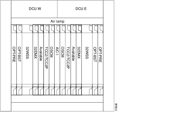
A reconfigurable OADM (ROADM) node allows you to add and drop wavelengths without changing the physical fiber connections. ROADM nodes are equipped with two 32WSS cards. 32DMX or 32DMX-O demultiplexers are typically installed, but are not required. Transponders (TXPs) and muxponders (MXPs) can be installed in Slots 6 and 12 and, if amplification is not used, in any open slot. Figure 4-18 shows an example of an amplified ROADM node configuration.
Figure 4-18 ROADM Node with BST-PRE, OPT-BST, and 32DMX Cards Installed
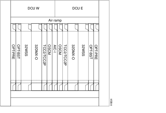
If the ROADM node receives a tilted optical signal, you can replace the single-slot 32DMX card with the double-slot 32DMX-O card to equalize the signal at the optical channel layer instead of the transport section layer. However, if 32DMX-O cards are installed, Slots 6 and 12 cannot be used for TXP or MXP cards.
Figure 4-19 shows an example of an ROADM with 32DMX-O cards installed.
Figure 4-19 ROADM Node with BST-PRE, OPT-BST, and 32DMX-O Cards Installed
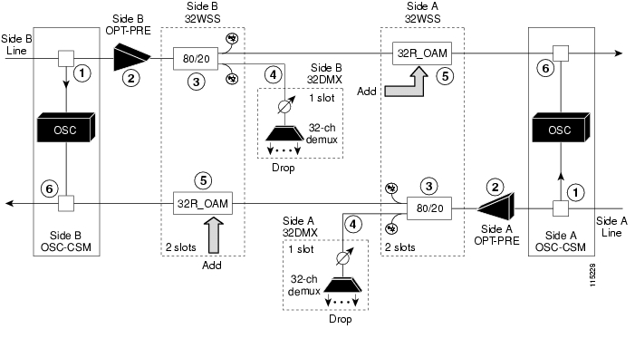
Figure 4-20 shows an example of a reconfigurable OADM east-to-west optical signal flow. The west-to-east optical signal flow follows an identical path through the west OSC-CSM and west 32WSS modules. In this example, OSC-CSM modules are installed so OPT-BST modules are not needed.
Figure 4-20 ROADM East to West Optical Signal Flow Example
1. The OSC-CSM receives the optical signal. It separates the optical service channel from the optical payload and sends the payload to the OPT-PRE module.
2. The OPT-PRE compensates for chromatic dispersion, amplifies the optical payload, and sends it to the 32WSS.
3. The 32WSS splits the signal into two components, one is sent to the DROP-TX port and the other is sent to the EXP-TX port.
4. The drop component goes to the 32DMX where it is attenuated, de-multiplexed, and dropped.
5. The express wavelength set goes to the 32WSS on the other side where it is demultiplexed. Channels are stopped or forwarded based upon their switch states. Forwarded wavelengths are multiplexed and sent to the OSC-CSM module.
6. The OSC-CSM combines the multiplexed payload with the OSC and sends the signal out the transmission line.
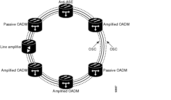
Anti-ASE Node
In a meshed ring network, the ONS 15454 requires a node configuration that prevents amplified spontaneous emission (ASE) accumulation and lasing. An anti-ASE node can be created by configuring a hub node or an OADM node with some modifications. No channels can travel through the express path, but they can be demultiplexed and dropped at the channel level on one side and added and multiplexed on the other side.
The hub node is the preferred node configuration when some channels are connected in passthrough mode. For rings that require a limited number of channels, combine AD-xB-xx.x and 4MD-xx.x cards, or cascade AD-xC-xx.x cards.
Figure 4-21 shows an example of traffic flow on an anti-ASE node that uses all wavelengths in the pass-through mode. Use MetroPlanner or another network planning tool to determine the best configuration for anti-ASE nodes.
Figure 4-21 Anti-ASE Node Channel Flow Example
Line Amplifier Node
A line node is a single ONS 15454 node equipped with OPT-PRE amplifiers or OPT-BST amplifiers and TCC2/TCC2P cards. Attenuators might also be required between each preamplifier and booster amplifier to match the optical input power value and to maintain the amplifier gain tilt value.
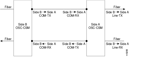
Two OSCM cards are connected to the east or west ports of the booster amplifiers to multiplex the optical service channel (OSC) signal with the pass-though channels. If the node does not contain OPT-BST amplifiers, you must use OSC-CSM cards rather than OSCM cards in your configuration. Figure 4-22 shows an example of a line node configuration.
Figure 4-22 Line Node Configuration Example
OSC Regeneration Node
The OSC regeneration node is added to the DWDM networks for two purposes:
•
•
OSC regeneration nodes require two OSC-CSM cards, as shown in Figure 4-23.
Figure 4-23 OSC Regeneration Line Node Configuration Example
Figure 4-24 shows the OSC regeneration node OSC signal flow.
Figure 4-24 OSC Regeneration Line Site Example
DWDM and TDM Hybrid Node Configurations
The node configuration is determined by the type of card that is installed in an ONS 15454 hybrid node. The ONS 15454 supports the following DWDM and TDM hybrid node configurations:
•
•
•
•
•
•
Note
1+1 Protected Flexible Terminal Node
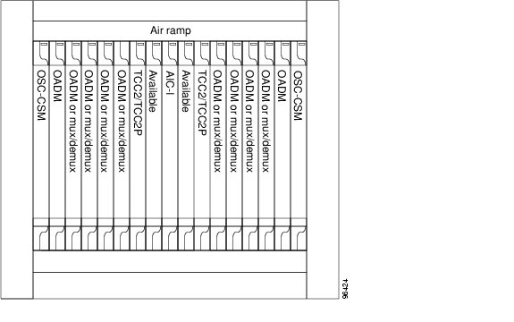
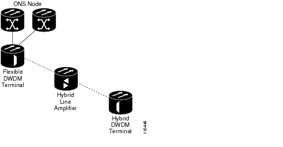
The 1+1 protected flexible terminal node is a single ONS 15454 node equipped with a series of OADM cards acting in a hub node configuration. This configuration uses a single hub or OADM node connected directly to the far-end hub or OADM node through four fiber links. This node configuration is used in a ring configured with two point-to-point links. The advantage of the 1+1 protected flexible terminal node configuration is that it provides path redundancy for 1+1 protected TDM networks (two transmit paths and two receive paths) using half of the DWDM equipment that is usually required. In the example shown in Figure 4-25, one node transmits traffic to the other node on both east and west sides of the ring for protection purposes. If the fiber is damaged on one side of the ring, traffic still arrives safely through fiber on the other side of the ring.
Figure 4-25 Double Terminal Protection Configuration
Figure 4-26 shows a 1+1 protected single-span link with hub nodes. 1+1 protected single-span link with hub nodes cannot be used in a hybrid configurations.
Figure 4-26 1+1 Protected Single-Span Link with Hub Nodes
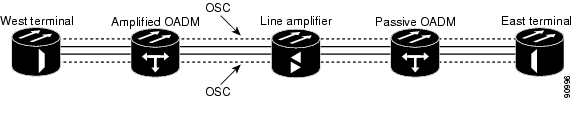
Figure 4-27 shows a 1+1 protected single-span link with active OADM nodes. 1+1 protected single-span link with active OADM nodes can be used in a hybrid configurations.
Figure 4-27 1+1 Protected Single-Span Link with Active OADM Nodes
Figure 4-28 shows a 1+1 protected single-span link with passive OADM nodes. 1+1 protected single-span link with passive OADM nodes can be used in a hybrid configurations.
Figure 4-28 1+1 Protected Single-Span Link with Passive OADM Nodes
Scalable Terminal Node
The scalable terminal node is a single ONS 15454 node equipped with a series of OADM cards and amplifier cards. This node type is more cost effective if a maximum of 16 channels are used (see Table 4-25). This node type does not support a terminal configuration exceeding 16 channels, because the 32-channel terminal site is more cost effective for 17 channels and beyond.
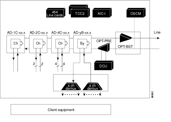
The OADM cards that can be used in this type of configuration are: AD-1C-xx.x, AD-2C-xx.x, AD-4C-xx.x, and AD-1B-xx.x. You can also use AD-4B-xx.x and up to four 4MD-xx.x cards. The OPT-PRE and/or OPT-BST amplifiers can be used. The OPT-PRE or OPT-BST configuration depends on the node loss and the span loss. When the OPT-BST is not installed, the OSC-CSM must be used instead of the OSCM card. Figure 4-29 shows a channel flow example of a scalable terminal node configuration.
Figure 4-29 Scalable Terminal Channel Flow Example
A scalable terminal node can be created by using band and/or channel OADM filter cards. This node type is the most flexible of all node types, because the OADM filter cards can be configured to accommodate node traffic. If the node does not contain amplifiers, it is considered a passive hybrid terminal node. Figure 4-30 shows an example of a scalable terminal node configuration. This node type can be used without add or drop cards.
Figure 4-30 Scalable Terminal Example
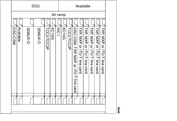
Hybrid Terminal Node
A hybrid terminal node is a single ONS 15454 node equipped with at least one 32MUX-O card, one 32DMX-O card, two TCC2/TCC2P cards, and TDM cards. If the node is equipped with OPT-PRE or OPT-BST amplifiers, it is considered an amplified terminal node. The node becomes passive if the amplifiers are removed. The hybrid terminal node type is based on the DWDM terminal node type described previously in this chapter. Figure 4-31 shows an example of an amplified hybrid terminal node configuration.
Figure 4-31 Amplified Hybrid Terminal Example
Figure 4-32 shows an example of a passive hybrid terminal node configuration.
Figure 4-32 Passive Hybrid Terminal Example
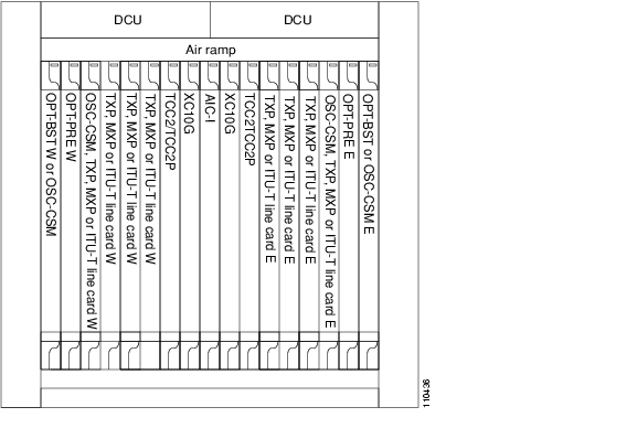
Hybrid OADM Node
A hybrid OADM node is a single ONS 15454 node equipped with at least one AD-xC-xx.x card or one AD-xB-xx.x card, and two TCC2/TCC2P cards. The hybrid OADM node type is based on the DWDM OADM node type previously described in this chapter. TDM cards can be installed in any available multi-speed slot. Review the plan produced by MetroPlanner to determine slot availability. Figure 4-33 shows an example of an amplified hybrid OADM node configuration. The hybrid OADM node can also become passive by removing the amplifier cards.
Figure 4-33 Hybrid Amplified OADM Example
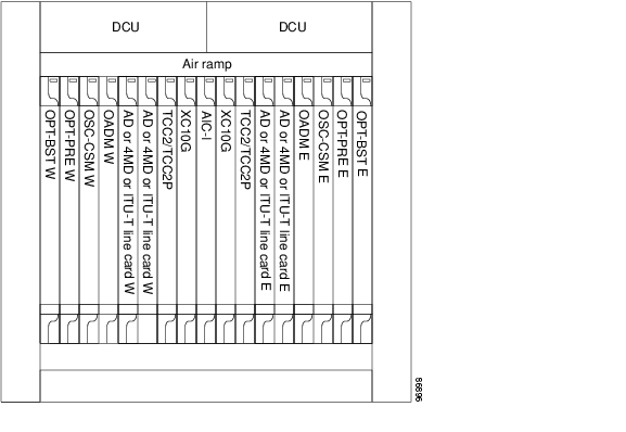
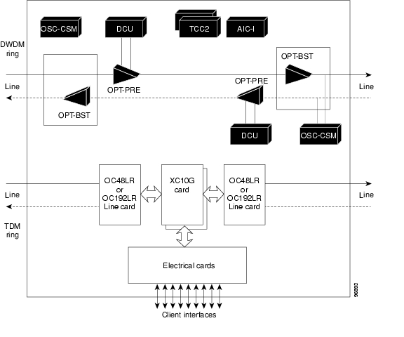
Hybrid Line Amplifier Node
A hybrid line amplifier node is a single ONS 15454 node with open slots for both TDM and DWDM cards. Figure 4-34 shows an example of a hybrid line amplifier node configuration.
Note
Figure 4-34 Hybrid Line Amplifier Example
A hybrid line node is another example of the hybrid line amplifier OADM node. A hybrid line node is single ONS 15454 node equipped with OPT-PRE amplifiers, OPT-BST amplifiers, and TCC2/TCC2P cards for each line direction. Both types of amplifiers can be used or just one type of amplifier. Attenuators might also be required between each preamplifier and booster amplifier to match the optical input power value and to maintain the amplifier gain tilt value. TDM cards can be installed in any available multi-speed slot. Review the plan produced by MetroPlanner to determine slot availability. Figure 4-35 shows a channel flow example of a hybrid line node configuration. Since this node contains both TDM and DWDM rings, both TDM and DWDM rings should be terminated even if no interactions are present between them.
Figure 4-35 Hybrid Line Amplifier Channel Flow Example
Amplified TDM Node
An amplified TDM node is a single ONS 15454 node that increases the span length between two ONS 15454 nodes that contain TDM cards and optical amplifiers. There are three possible configurations for an amplified TDM node:
•
•
•
The client cards that can be used in an amplified TDM node are:
•
•
•
•
•
•
Figure 4-36 shows the first amplified TDM node scenario with an OPT-BST amplifier.
Figure 4-36 Amplified TDM Example with an OPT-BST Amplifier
Figure 4-37 shows the first amplified TDM node channel flow configuration with OPT-BST amplifiers.
Figure 4-37 Amplified TDM Channel Flow Example With OPT-BST Amplifiers
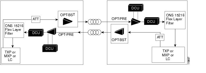
Figure 4-38 shows the second amplified TDM node configuration with client cards, AD-1C-xx.x cards, OPT-BST amplifiers, OPT-PRE amplifiers, and FlexLayer filters.
Figure 4-38 Amplified TDM Example with FlexLayer Filters
Figure 4-39 shows the second amplified TDM node channel flow configuration with client cards, OPT-BST amplifiers, OPT-PRE amplifiers, and FlexLayer filters.
Figure 4-39 Amplified TDM Channel Flow Example With FlexLayer Filters
Figure 4-40 shows the third amplified TDM channel flow configuration with client cards, OPT-BST amplifiers, OPT-PRE amplifiers, AD-1C-xx.x cards, and OSC-CSM cards.
Figure 4-40 Amplified TDM Channel Flow Example With Amplifiers, AD-1C-xx.x Cards, and OSC-CSM Cards
DWDM Topologies
There are two main DWDM network types: metro core, where the channel power is equalized and dispersion compensation is applied, and metro access, where the channels are not equalized and dispersion compensation is not applied. Metro Core networks often include multiple spans and amplifiers, thus making optical signal-to-noise ratio (OSNR) the limiting factor for channel performance. Metro Access networks often include a few spans with very low span loss; therefore, the signal link budget is the limiting factor for performance. The DWDM network topologies supported by the ONS 15454 are:
•
•
•
•
•
•
•
Hubbed Rings
In the hubbed ring topology ( Figure 4-41), a hub node terminates all the DWDM channels. A channel can be provisioned to support protected traffic between the hub node and any node in the ring. Both working and protected traffic use the same wavelength on both sides of the ring. Protected traffic can also be provisioned between any pair of OADM nodes, except that either the working or the protected path must be regenerated in the hub node.
Protected traffic saturates a channel in a hubbed ring, that is, no channel reuse is possible. However, the same channel can be reused in different sections of the ring by provisioning unprotected multi-hop traffic. From a transmission point of view, this network topology is similar to two bidirectional point-to-point links with OADM nodes.
Figure 4-41 Hubbed Ring
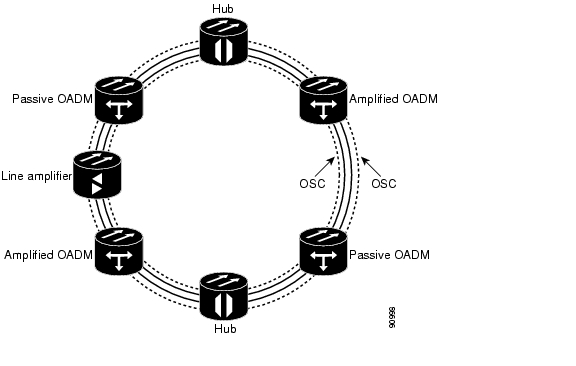
Multi-hubbed Rings
A multi-hubbed ring ( Figure 4-42) is based on the hubbed ring topology, except that two or more hub nodes are added. Protected traffic can only be established between the two hub nodes. Protected traffic can be provisioned between a hub node and any OADM node only if the allocated wavelength channel is regenerated through the other hub node. Multi-hop traffic can be provisioned on this ring. From a transmission point of view, this network topology is similar to two or more point-to-point links with OADM nodes.
Figure 4-42 Multi-hubbed Ring
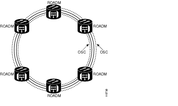
Any-to-Any Rings
The any-to-any ring topology shown in Figure 4-43 contains only reconfigurable OADM (ROADM) nodes, or ROADM nodes with Optical Service Channel (OSC) regeneration or amplifier nodes. This topology potentially allows you to route every wavelength from any source to any destination node inside the network.
Figure 4-43 Any-to-Any Ring
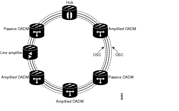
Meshed Rings
The meshed ring topology ( Figure 4-44 does not use hubbed nodes; only amplified and passive OADM nodes are present. Protected traffic can be provisioned between any two nodes; however, the selected channel cannot be reused in the ring. Unprotected multi-hop traffic can be provisioned in the ring. A meshed ring must be designed to prevent ASE lasing. This is done by configuring a particular node as an anti-ASE node. An anti-ASE node can be created in two ways:
•
•
Figure 4-44 Meshed Ring
Linear Configurations
Linear configurations are characterized by the use of two terminal nodes (west and east). The terminal nodes must be equipped with a 32MUX-O card and a 32DMX-O card, or a 32WSS card with a 32DMX or 32DMX-O card. OADM or line amplifier nodes can be installed between the two terminal nodes. Only unprotected traffic can be provisioned in a linear configuration. Figure 4-45 shows five ONS 15454 nodes in a linear configuration with an OADM node.
Figure 4-45 Linear Configuration with an OADM Node
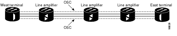
Figure 4-46 shows five ONS 15454 nodes in a linear configuration without an OADM node.
Figure 4-46 Linear Configuration without an OADM Node
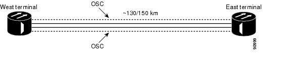
Single-Span Link
Single-span link is a type of linear configuration characterized by a single-span link with preamplification and post-amplification. A span link is also characterized by the use of two terminal nodes (west and east). The terminal nodes are usually equipped with a 32MUX-O card and a 32DMX-O card. However, a 32WSS card and a 32DMX or a 32DMX-O card can be installed. Software R4.6 and higher also supports single-span links with AD-4C-xx.x cards. Only unprotected traffic can be provisioned on a single-span link.
Figure 4-47 shows ONS 15454s in a single-span link. Eight channels are carried on one span. Single-span link losses apply to OC-192 LR ITU cards. The optical performance values are valid assuming that the sum of the OADM passive nodes insertion losses and the span losses does not exceed 35 dB.
Figure 4-47 Single-Span Link
Hybrid Networks
The hybrid network configuration is determined by the type of node that is used in an ONS 15454 network. Along with TDM nodes, the ONS 15454 supports the following hybrid node types: 1+1 protected flexible terminal, scalable terminal, hybrid terminal, hybrid OADM, hybrid line amplifier, and amplified TDM.
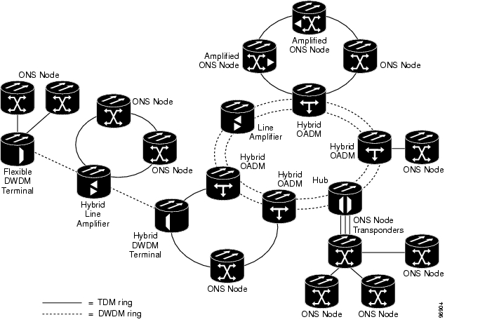
Figure 4-48 shows ONS 15454s in a hybrid TDM and DWDM configurations.
Figure 4-48 Hybrid Network Example
DWDM and TDM layers can be mixed in the same node; however they operate and are provisioned independently. The following TDM configurations can be added to a hybrid network:
•
•
•
•
Figure 4-49 shows ONS 15454s in a hybrid point-to-point configuration.
Figure 4-49 Hybrid Point-to-Point Network Example
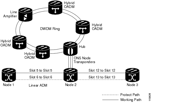
Figure 4-50 shows ONS 15454s in a hybrid linear ADM configuration.
Figure 4-50 Hybrid Linear ADM Network Example
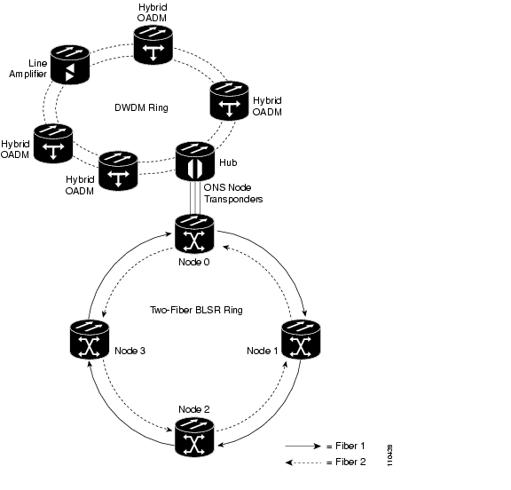
Figure 4-51 shows ONS 15454s in a hybrid BLSR configuration.
Figure 4-51 Hybrid BLSR Network Example
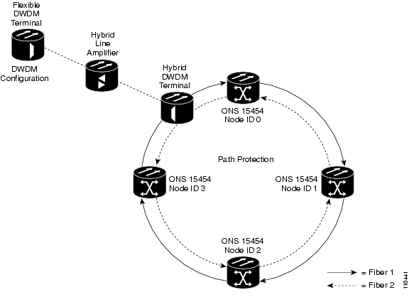
Figure 4-52 shows ONS 15454s in a hybrid path protection configuration.
Figure 4-52 Hybrid Path Protection Network Example
DWDM Network Topology Discovery
Each ONS 15454 DWDM node has a network topology discovery function that can:
•
•
•
ONS 15454 DWDM nodes use node services protocol (NSP) to automatically update nodes whenever a change in the network occurs. NSP uses two information exchange mechanisms: hop-by-hop message protocol and broadcast message protocol. Hop-by-hop message protocol elects a master node and exchanges information between nodes in a sequential manner simulating a token ring protocol as follows:
•
•
•
NSP broadcast message protocol distributes information that is to be shared by all ONS 15454 DWDM nodes on the same network. Broadcast message delivery is managed in an independent way from delivery of the two tokens. Moreover, no synchronization among broadcast messages is required; every node is authorized to send a broadcast message any time it is necessary.
Optical Performance
This section provides optical performance information for ONS 15454 DWDM networks. The performance data is a general guideline based upon the network topology, node type, client cards, fiber type, number of spans, and number of channels. The maximum number of nodes that can be in an ONS 15454 DWDM network is 16. The DWDM topologies and node types covered in this section are shown in Table 4-26.
Table 4-26 Supported Topologies, and Node Types
32
SMF-281
E-LEAF2
TW-RS3
Ring
Linear
Linear without OADM
Hub
Active OADM
Passive OADM
Terminal
Line
OSC regeneration
16
SMF-28
Ring
Linear
Linear without OADM
Hub
Active OADM
Passive OADM
Terminal
Line
OSC regeneration
8
SMF-28
Linear without OADM
Terminal
Line
1 SMF-28 = single-mode fiber 28
2 E-LEAF = enhanced large effective area fiber
3 TW-RS = TrueWave reduced slope fiber
The following tables provide optical performance estimates for open and closed ONS 15454 rings and linear networks with OADM nodes.
Table 4-27 shows the optical performance for a 32-channel hubbed ring SMF fiber. Span losses shown in the table assume:
•
•
•
Table 4-27 Span Loss for 32-Channel Ring and Linear Networks with OADM Nodes Using SMF Fiber
1
34 dB
26 dB
26 dB
36 dB
37 dB
33 dB
30 dB
32 dB
34 db
30 dB
2
28 dB
21 dB
20 dB
30 dB
31 dB
28 dB
25 dB
27 Db
29 dB
25 dB
3
26 dB
17 dB
15 dB
28 dB
29 dB
26 dB
23 dB
25 dB
26 dB
23 dB
4
24 dB
—
—
25 dB
26 dB
23 dB
20 dB
22 dB
24 dB
20 dB
5
22 dB
—
—
24 dB
25 dB
22 dB
16 dB
20 dB
23 dB
16 dB
6
20 dB
—
—
22 dB
24 dB
19 dB
—
17 dB
21 dB
—
7
181 dB
—
—
21 dB
23 dB
16 dB
—
—
19 dB
—
1 0.5 dB of OSNR impairment recovered by FEC margin @ BER > 10-6
Table 4-28 shows the optical performance for 16-channel networks using SMF fiber. Span loss values assume the following:
•
•
•
Table 4-29 shows the optical performance for 32-channel networks using TW-RS fiber. Span loss values assume the following:
•
•
•
Table 4-30 shows the optical performance for 32-channel networks using E-LEAF fiber. Span loss values assume the following:
•
•
•
Optical Performance for Linear Networks Without OADM Nodes
The following tables list the reference optical performances for linear networks without OADM nodes. Table 4-31 shows the optical performance for 32-channel linear networks using SMF fiber. Span loss values assume the following:
•
•
•
Table 4-32 shows the optical performance for 32-channel linear networks using TW-RS fiber. Span loss values assume the following:
•
•
•
Table 4-33 shows the optical performance for 32-channel linear networks using E-LEAF fiber. Span loss values assume the following:
•
•
•
Table 4-34 shows the optical performance for 16-channel linear networks using SMF fiber. Span loss values assume the following:
•
•
•
•
•
Table 4-35 shows the optical performance for 8-channel linear networks using SMF fiber. Span loss values assume the following:
•
•
•
Optical Performance for ROADM Rings and Linear Networks
The following tables list the reference optical performances for ROADM rings and linear networks. Table 4-36 shows the optical performance for 32-channel linear or ring networks using SMF fiber with only ROADM nodes installed. Span loss values assume the following:
•
•
•
Table 4-37 shows the optical performance for 32-channel linear or ring network with ROADM and OADM nodes using SMF fiber. Span loss values assume the following:
•
•
•
Table 4-37 Span Loss for 32-Channel Ring and Linear Networks with ROADM and OADM Nodes Using SMF Fiber
1
30 dB
23 dB
24 dB
31 dB
34 dB
31 dB
28 dB
29 dB
30 dB
28 dB
2
26 dB
19 dB
19 dB
27dB
27 dB
26 dB
23 dB
26 dB
27 dB
23 dB
3
23 dB
—
—
25 dB
26 dB
23 dB
21 dB
23 dB
24 dB
21 dB
4
21 dB
—
—
23 dB
24 dB
22 dB
18 dB
21 dB
22 dB
18 dB
5
20 dB
—
—
22 dB
23 dB
20 dB
13 dB
20 dB
21 dB
13 dB
6
17 dB
—
—
19 dB
22 dB
18 dB
—
17 dB
18 dB
—
7
151 dB
—
—
17 dB
21 dB
16 dB
—
15 1 dB
16 dB
—
1 0.5 dB of OSNR impairment recovered by FEC margin @ BER > 10-6
The following tables show the pass/fail criteria for eight and sixteen ROADM nodes. Table 4-38 shows the pass/fail criteria for eight ROADM nodes (seven spans) required for any-to-any node circuit reconfigurations:
•
•
Table 4-39 shows the pass/fail criteria for 16 ROADM nodes (15 spans) required for any-to-any node circuit reconfigurations.
•
•
Table 4-39 Pass/Fail Criteria for 32-Channel, 16-Node ROADM Rings Using SMF Fiber
1
OPT-PRE
<151
<15 1
<15 1
Yes
Yes
<15 1
<15 1
<15 1
<15 1
—
2
OPT-PRE
<15 1
<15 1
<15 1
Yes
Yes
<15 1
<15 1
<15 1
<15 1
—
3
OPT-PRE
<15 1
<15 1
<15 1
Yes
Yes
<15 1
<15 1
<15 1
<15 1
—
4
OPT-PRE
<15 1
<15 1
<15 1
Yes
Yes
<15 1
<15 1
<15 1
<15 1
—
5
OPT-PRE
<15 1
<15 1
<15 1
Yes
Yes
<15
<15
<15
<15
—
6
OPT-PRE
<15 1
<15 1
<15 1
Yes
Yes
<15 1
<15 1
<15 1
<15 1
—
7
OPT-PRE OPT-BST
<15 1
<15 1
<15 1
Yes
Yes
<15 1
<15 1
<15 1
<15 1
—
8
OPT-PRE OPT-BST
<15 1
<15 1
<15 1
Yes
Yes
<15 1
<15 1
<15 1
<15 1
—
9
OPT-PRE OPT-BST
<15 1
<15 1
<15 1
Yes
Yes
<15 1
<15 1
<15 1
<15 1
—
10
OPT-PRE OPT-BST
<15 1
<15 1
<15 1
Yes
Yes
<15 1
<15 1
<15 1
<15 1
—
11
OPT-PRE OPT-BST
<15 1
<15 1
<15 1
Yes
Yes
<15 1
<15 1
<15 1
<15 1
—
12
OPT-PRE OPT-BST
<15 1
<15 1
<15 1
Yes
Yes
<15 1
<15 1
<15 1
<15 1
—
13
OPT-PRE OPT-BST
<15 1
<15 1
<15 1
Yes
Yes
<15 1
<15 1
<15 1
<15 1
—
14
OPT-PRE OPT-BST
<15 1
<15 1
<15 1
Yes
Yes
<15 1
<15 1
<15 1
<15 1
—
15
OPT-PRE OPT-BST
<15 1
<15 1
<15 1
Yes
Yes
<15 1
<15 1
<15 1
<15 1
—
1 Cisco MetroPlanner calculates the maximum ring circumference and number of nodes that can be supported.
Optical Performance for Single-Span Networks
Table 4-40 lists the span loss for a single-span link configuration with eight channels. The optical performance for this special configuration is given only for Classes A and C. This configuration assumes a maximum channel capacity of eight channels (8 dBm nominal channel power) used without any restrictions on the 32 available channels.
Table 4-41 lists the span loss for a single-span link configuration with 16 channels. The optical performance for this special configuration is given only for Class A and Class C. This configuration assumes a maximum channel capacity of 16 channels (5 dBm nominal channel power) used without any restrictions on the 32 available channels.
Table 4-42 lists the span loss for a single-span link configuration with AD-1C-x.xx cards, OPTPRE amplifiers, and OPT-BST amplifiers. The single-span link with a flexible channel count is used both for transmitting and receiving. If dispersion compensation is required, a DCU can be used with an OPT-PRE amplifier. The optical performance for this special configuration is given for Classes A through G (8 dBm nominal channel power) used without any restrictions on the 32 available channels.
Table 4-42 Span Loss for Single-Span Link with AD-1C-xx.x Cards, OPT-PRE Amplifiers, and OPT-BST Amplifiers
With OSCM cards1
1
37 dB
31 dB
31 dB
37 dB
37 dB
37 dB
37 dB
Hybrid with OSC-CSM cards2
1
35 dB
31 dB
31 dB
35 dB
35 dB
35 dB
35 dB
1 OSCM sensitivity limits the performance to 37 dB.
2 OSC-CSM sensitivity limits the performance to 35 dB when it replaces the OSCM.
Table 4-43 lists the span loss for a single-span link configuration with one channel and OPT-BST amplifiers. The optical performance for this special configuration is given for Classes A through G. Classes A, B, and C use 8 dBm nominal channel power. Classes D, E, F, and G use 12 dBm nominal channel power. There are no restriction on the 32 available channels. That is, a line card, transponder, or muxponder wavelength can be extracted from the 32 available wavelengths. Also, the optical service channel is not required.
Automatic Power Control
Each ONS 15454 DWDM node has an automatic power control (APC) feature that performs the following functions:
•
•
•
Note
Amplifier software uses a control gain loop with fast transient suppression in order to keep the channel power constant regardless of any variation in the number of channels. Amplifiers monitor the input power variation and change the output power according to the calculated gain set point. Shelf controller software emulates the control output power loop to adjust for fiber degradation. To perform this function, the TCC2/TCC2P needs to know the channel distribution, which is provided by a signaling protocol, and the expected per channel power, which is provisioned by user. Using this method, the TCC2/TCC2P is able to compare the actual amplifier output power with the expected amplifier output power that is matched by modifying the set points if there are any discrepancies.
APC at the Amplifier
In constant gain mode, the amplifier power out control loop performs the following input and output power calculations, where G represents the gain and t represents time:
Pout (t) = G * Pin (t) (mW)
Pout (t) = G + Pin (t) (dB)
In a power equalized optical system the total input power is proportional to the number of channels. Amplifier software compensates for any variation of the input power as a variation in the number of channels carried by the incoming signal.
Amplifier software identifies changes in the read input power in two different instances, t1 and t2 as a change in the carried traffic. The letters m and n below represent two different channel numbers. Pin/ch represents the per channel input power as follows:
Pin (t1) = nPin/ch
Pin (t2) = mPin/ch
Amplifier software applies the variation in the input power to the output power with a reaction time that is a fraction of a millisecond. This keeps the power constant on each channel at the output amplifier, even during a channel upgrade or a fiber cut.
Amplifier parameters are configured using east and west conventions for ease of use. Selecting west provisions parameters for the preamplifier receiving from the west and the booster amplifier transmitting to the west. Selecting east provisions parameters for the preamplifiers receiving from the east and the booster amplifier transmitting to the east.
Starting from the expected per channel power, the amplifiers are automatically able to calculate the gain set-point when the first channel is provisioned. An amplifier gain set-point is calculated in order to make it equal to the loss of the span preceding the amplifier itself. Once the gain is calculated, the set point is no longer changed by the amplifier. Amplifier gain is recalculated every time the number of provisioned channels returns to zero. If you need to force a recalculation of the gain, move the number of channels back to zero.
APC at the Node
The amplifier calculates gain set points to compensate for span loss on the preceding node. Changing network conditions that affect span loss (aging fiber, aging components, or changes in operating conditions) makes the gain calculation invalid. The goal of APC at the node layer is to recalculate the gain to make it equal to the span loss.
APC corrects the gain or express variable optical attenuator (VOA) set points by calculating the difference between the power value read by the photodiodes and the expected power value calculated using the following parameters:
•
•
•
Channel distribution is determined by the sum of provisioned and failed channels. Information about provisioned wavelengths is sent to APC on the applicable nodes during the circuit creation phase. Information about failed channels is collected through a signaling protocol that monitors alarms on ports in the applicable nodes and distributes that information to all the other nodes in the network.
ASE calculations purify the noise from the power level reported from the photodiode. Each amplifier can compensate for its own noise (SNR) but cascaded amplifiers cannot compensate for ASE generated by preceding nodes. The ASE effect increases when the number of channels decreases; therefore, a correction factor must be calculated in each amplifier of the ring to compensate for ASE build-up.
APC is a network-level feature. The APC algorithm designates a master node that is responsible for starting APC hourly or every time a new circuit is provisioned or removed. Every time the master node signals for APC to start, gain and VOA set points are evaluated on all nodes in the network. If corrections are needed in different nodes, they are always performed sequentially following the optical paths starting from the master node.
APC corrects the power level only if the variation exceeds the hysteresis thresholds of +/-0.5 dB. Any power level fluctuation within the threshold range is skipped since it is considered negligible. Since APC is designed to follow slow time events, APC skips corrections greater than 3 dB that is the total typical aging margin provisioned by the user during the network design phase. When the first channel is provisioned or amplifiers are turned up for the first time, APC does not apply the 3 dB rule. In this case APC corrects all the power differences to turn-up the node.
Note
To avoid large power fluctuations, APC adjusts power levels incrementally. The maximum power correction applied each iteration is +/-0.5 dB until the optimal power level is reached. For example a gain deviation of 2 dB is corrected in four steps. Each of the four steps requires a complete APC check on every node in the network. APC can correct up to a maximum of 3 dB on an hourly basis. If degradation occurs in a longer time period, APC will compensate for it by using all margins provisioned by the user during installation.
When no margin is available adjustments cannot be made because set points exceed ranges and APC communicates the event to CTC, CTM, and TL1 through an APC Fail condition. APC will clear the APC fail condition when set-points return to the allowed ranges.
APC cannot be started or disabled by the user. APC automatically disables itself when:
•
•
•
•
•
The APC state (Enable/Disable) is located on every node and can be retrieved by the CTC or TL1 interface. If an event that disables APC occurs in one of the network nodes, APC will be disabled on all the others and the APC state changes to DISABLE - INTERNAL. The DISABLE state is raised only by the node where the problem occurred to simplify troubleshooting.
APC raises the following standing conditions at the port level in CTC, TL1, and SNMP:
APC Out of Range - APC cannot assign a new setpoint for a parameter this is allocated to a port because the new setpoint exceeds the parameter range.
APC Correction Skipped - APC skipped a correction to one parameter allocated to a port because the difference between the expected and current values exceeds the +/- 3 dB security range.
After the error condition is cleared, signaling protocol enables APC on the network and the APC DISABLE - INTERNAL condition is cleared. Because APC is required after channel provisioning to compensate for ASE effects, all optical channel network connection (OCHNC) circuits that you provision during the disabled APC state are kept in the Out-of-Service and Autonomous, Automatic In-Service (OOS-AU,AINS [ANSI]) or Unlocked-disabled,automaticInService (ETSI) service state until APC is enabled. OCHNCs automatically go into the In-Service and Normal (ISNR [ANSI]) or Unlocked-enabled (ETSI) service state only after APC is enabled.
Managing APC
The automatic power control status is indicated by the following four APC states shown in the node view status area:
•
•
•
•
You can view the automatic power control information and disable and enable APC manually on the Maintenance > DWDM > APC subtab shown in Figure 4-53.
Caution
Figure 4-53 Automatic Power Control
The APC subtab provides the following information:
•
•
•
•
•
ROADM Power Equalization Monitoring
Reconfigurable OADM (ROADM) nodes allow you to monitor the 32WSS card equalization functions on the Maintenance > DWDM > Power Monitoring subtab as shown in Figure 4-54. The tab shows the input channel power (Padd), the express or pass-through (Ppt) power and the power level at output (Pout).
Figure 4-54 Power Monitoring Subtab
Span Loss Verification
Span loss measurements can be performed from the Maintenance > DWDM > WDM Span Check subtab as shown in Figure 4-55. The CTC span check compares the far-end OSC power with the near-end OSC power. A "Span Loss Out of Range" condition is raised when the measured span loss is higher than the maximum expected span loss. It is also raised when the measured span loss is lower than the minimum expected span loss and the difference between the minimum and maximum span loss values is greater than 1 dB. The minimum and maximum expected span loss values are calculated by Cisco MetroPlanner for the network and imported into CTC. However, you can manually change the minimum and expected span loss values.
CTC span loss measurements provide a quick span loss check and are useful whenever changes to the network occur, for example after you install equipment or repair a broken fiber. CTC span loss measurement resolutions are:
•
•
For ONS 15454 span loss measurements with higher resolutions, an optical time domain reflectometer (OTDR) must be used.
Figure 4-55 Span Loss Verification
Automatic Node Setup
Automatic node setup (ANS) is a TCC2/TCC2P function that adjusts values of the VOAs on the DWDM channel paths to equalize the per-channel power at the amplifier input. This power equalization means that at launch, all the channels have the same amplifier power level, independent from the input signal on the client interface and independent from the path crossed by the signal inside the node. This equalization is needed for two reasons:
1.
2.
To support ANS, the integrated VOAs and photodiodes are provided in the following ONS 15454 DWDM cards:
•
•
•
•
•
•
Optical power is equalized by regulating the VOAs. Based on the expected per-channel power, ANS automatically calculates the VOA values by:
•
•
VOAs operate in one of three working modes:
•
•
–
–
–
•
In the normal operating mode, OADM band card VOAs are set to a constant attenuation, while OADM channel card VOAs are set to a constant power. ANS requires the following VOA provisioning parameters to be specified:
•
•
To allow you to modify ANS values based on your DWDM deployment, provisioning parameters are divided into two contributions:
•
•
The ANS equalization algorithm requires knowledge of the DWDM transmission element layout as follows:
•
•
•
ANS assumes that every DWDM port has a line direction parameter that is either West to East (W-E) or East to West (E-W). ANS automatically configures the mandatory optical connections according to following main rules:
•
•
•
•
•
•
Optical patch cords are passive devices that are not autodiscovered by ANS. However, optical patch cords are used to build the alarm correlation graph. ANS uses CTC and TL1 as the user interfaces to:
•
•
•
•
•
After you launch ANS, the following statuses are provided for each ANS parameter:
•
•
•
•
•
Optical connections are identified by the two termination points, each with an assigned slot and port. ANS checks that a new connection is feasible (according to embedded connection rules) and returns a denied message in the case of a violation.
ANS requires provisioning of the expected wavelength. When provisioning the expected wavelength, the following rules apply:
•
•
•
•
Automatic Node Setup Parameters
All ONS 15454 ANS parameters are calculated by Cisco MetroPlanner for nodes configured for metro core networks. (Parameters must be configured manually for metro access nodes.) Cisco MetroPlanner exports the calculated parameters to an ASCII file called "NE Update." In CTC, you can import the NE Update file to automatically provision the node. Table 4-45 shows ANS parameters arranged in east and west, transmit and receive groups.
Viewing and Provisioning ANS Parameters
All ANS parameters can be viewed and provisioned from the node view Provisioning > WDMANS > Provisioning subtab, shown in Figure 4-56. The WDM-ANS > Provisioning > Provisioning subtab presents the parameters in the following tree view:
•
•
–
•
•
•
•
•
•
•
•
–
•
•
•
–
•
•
•
Figure 4-56 WDM-ANS Provisioning
The ANS parameters that appear in the WDM-ANS > Provisioning subtab depend on the node type. Table 4-47 shows the DWDN node configurations and their ANS parameters.
Table 4-48 shows the following information for all ONS 15454 ANS parameters:
•
•
•
•
•
•
![]()
![]()
![]()
![]()
![]()
![]()
![]()
![]()
Posted: Tue Nov 27 11:14:20 PST 2007
All contents are Copyright © 1992--2007 Cisco Systems, Inc. All rights reserved.
Important Notices and Privacy Statement.