|
|

Table Of Contents
1.1 Setting up TL1 Communication
1.4 TL1 Commands by User Security
1.5 Provisioning a DS3E Card in CTC Using TL1
1.7 TL1 Command Completion Behavior
1.7.2 Retrieval of Cross Connections
1.8.2 Split E and F Access Modes
1.8.4 Split A and B Access Modes
1.8.5 Creating Test Access Points
1.8.6 Connecting Test Access Points
1.8.7 Changing Test Access Modes
1.8.8 Disconnecting Test Access Modes
1.8.9 Deleting Test Access Points
Getting Started
Transaction Language 1 (TL1) is a subset of the input and output messages contained in the International Telecommunications Union (ITU) Man-Machine Language (MML). TL1 provides a standard set of messages that can be used for communicating between operating systems and network elements, and personnel and network elements. The ONS 15454 and ONS 15327 can support up to 20 concurrent TL1 sessions in this release. For more information about TL1, refer to Telcordia document GR-833-CORE, Network Maintenance: Network Element and Transport Surveillance Messages.
This chapter provides information and procedures for getting started with TL1:
•
Setting up TL1 communication
•
•
•
•
•
•
•
1.1 Setting up TL1 Communication
The period during which a user is logged into the ONS 15454 or ONS 15327 is called a session. There are three options you can use to open a session (login):
•
•
•
When you logout of any of these options, you are closing a session.
The ONS 15454 and ONS 15327 allow a maximum of 20 concurrent TL1 sessions using any one or any combination of the options listed above. For information on issuing commands to multiple nodes, see "TL1 Gateway."
1.1.1 Open a TL1 session
Use the following procedures to open a TL1 session via the CTC, telnet, or craft interface. In the procedures the Activate and Cancel User commands are shown in their input format. For more information about these and other commands and messages, see "TL1 Command Descriptions."
Procedure: Open a TL1 Session Via the CTC
Step 1
Step 2
Step 3
Step 4
Step 5
A TL1 interface window opens. There are three sub-windows in the TL1 interface window: Request history, Message log, and TL1 request. Type commands in the TL1 request window. You will see responses in the Message log window. The Request history window allows you to recall previous commands by clicking on them.
Step 6
Step 7
ACT-USER:[<TID>]:<UID>:<CTAG>::<PID>; and press Enter.
Note
Step 8
CANC-USER:[<TID>]:<USERID>:<CTAG>; and press Enter.
Procedure: Open a TL1 Session Via Telnet
To access TL1 commands in a telnet session over a craft interface or a LAN connection (TCC+ front panel or backplane pins) you can choose from several ports. Port number 3082 is a raw TCP/IP port; it will not echo and it will not prompt the user. Port number 3083 is a telnet port that uses the telnet protocol and associated telnet escape sequences. Port number 2361 is supported for backward compatibility with earlier releases and has the same behavior as Port 3083 (telnet port). The following procedure is for use on PCs with a Windows operating system.
Step 1
Step 2
TELNET <NODE IP ADDRESS OR NODE NAME> <PORT NUMBER> and press Enter.
The Node IP address or Node Name refers to the IP address or Node Name of the node you want to communicate with. Port number is the port (2361, 3082, or 3083) where TL1 commands are understood. If the connection is successful, a screen opens with a prompt.
Step 3
ACT-USER:[<TID>]:<UID>:<CTAG>::<PID>;
Note
Step 4
CANC-USER:[<TID>]:<USERID>:<CTAG>;
Procedure: Open a TL1 Session Via Craft Interface
The TCC+/XTC has two built-in interface ports for accessing the ONS 15454. With one RJ-45 LAN connection you can access the system using a standard browser interface. In the browser interface, you can perform local and remote Operations, Administration, Maintenance, and Provisioning (OAM&P) functions and open a VT100 emulation window to enter TL1 commands. If a browser is not available, you can access the system using a nine-pin RS-232 port. The RS-232 port supports VT100 emulation such that TL1 commands may be entered directly without a browser.
Step 1
Step 2
a.
b.
c.
d.
e.
Step 3
Step 4
ACT-USER:[<TID>]:<UID>:<CTAG>::<PID>;
Note
Step 5
CANC-USER:[<TID>]:<USERID>:<CTAG>;
1.2 TL1 Command Syntax
TL1 commands conform to the following syntax:
a:b:c:d:e: ... z;
where:
"a" is the command code
"b" is the target identifier (TID)
"c" is the access identifier (AID) or the user identifier (UID)
"d" is the correlation tag (CTAG)
"e: ... z;" are other positions required for various commands
The TID, AID, and CTAG route and control the TL1 command. Other parameters provide additional information required to complete the action requested by the command. TL1 command codes, parameter names and parameter values can be either uppercase or lowercase exclusively or any combination of the two, unless specifically noted in the command description.
The TID is a unique name given to each system when it is installed. The name identifies the particular NE (in this case, the ONS 15454 or ONS 15327), to which each command is directed. Each TID can have a maximum of 20 ASCII characters limited to letters, digits, and hyphens, but each TID must start with an alphabetic character. The presence of the TID is required in all input commands, but its value can be null (represented by two successive colons). The TID can be null when the operating system directly communicates with the target NE. The recommended value for the TID, when it is used, is the target's CLLI code. To establish the TID for an ONS 15454/15327 node, use the Provisioning > General tabs in CTC.
Note
The AID is an access code used to identify and address specific objects within the ONS 15454/ONS 15327. These objects include individual pieces of equipment, transport spans, access tributaries, and other objects.
The CTAG is a unique identifier given to each input command by the operator. When the ONS 15454/ONS 15327 system responds to a specific command, it includes the command's CTAG in the reply. Including the CTAG eliminates discrepancies about which response corresponds to which command. Valid CTAG values include strings of up to six characters comprised of identifiers (alphanumeric, beginning with a letter) or decimal numerals (a string of decimal digits with an optional non-trailing ".").
The following specification characters are used throughout this document as a vehicle for defining the syntax:
•
•
•
•
1.3 Autonomous Messages
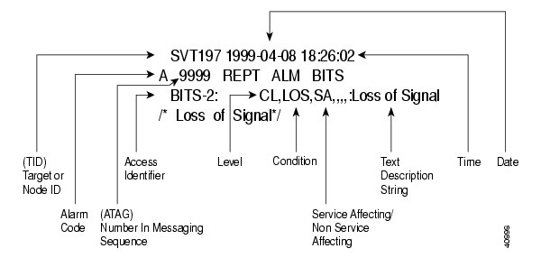
The autonomous TL1 messages are included in "TL1 Command Descriptions" and listed alphabetically. Figure 1-1 shows the autonomous message format. The autonomous message tag (ATAG) is used for message sequencing. The number is incremented by one for each autonomous message sent by the ONS 15454 or ONS 15327. The ONS 15454 and ONS 15327 use whole numbers 0000 to 9999.
Figure 1-1 Autonomous message format
1.3.1 Alarm Codes
The alarm code indicates the severity of the autonomous message. Valid values for alarm codes in decreasing order of severity are as follows:
•
•
•
•
Critical, Major, and Minor correspond to the reporting of alarmed events. The Non-alarm message designation is used when the NE is reporting non-alarmed events, periodic measurements, or results of previously-scheduled diagnostics or audits. If multiple alarms are reported in the same message, the alarm code is the highest severity of those being reported.
The following is an example of an output message that includes the Critical alarm code:
ab7-56 1970-01-01 16:02:10
*C 4 REPT ALM EQPT
"SYSTEM:CR,HITEMP,NSA,,,,:\"High Temperature\",TCC"For more information about alarms, see "TL1 Alarms and Errors."
1.4 TL1 Commands by User Security
The following table specifies command access privileges for each user security level.
User security levels limit the amount of time a user can leave the system idle before the TL1 session is locked to prevent unauthorized users from making changes. Higher security levels have shorter idle times. Table 1-2 shows security levels and their idle times.
Table 1-2 Security Idle Times
Retrieve
Unlimited
Maintenance
60 minutes
Provisioning
30 minutes
Superuser
15 minutes
1.5 Provisioning a DS3E Card in CTC Using TL1
The DS3E card can autosense the framing being received and set the framing accordingly; however, this framing autosense feature can only be set using CTC. Use CTC to set the FMT attribute on a DS3E card to autoprovision which results in the FMT field being blanked out for a few seconds while the DS3E card is determining the framing mode coming into that particular port. The FMT field is then set accordingly to unframed, M23, or CBit. If the DS3E card is not present (pre-provisioned), setting the FMT field to autoprovision will result in the FMT field defaulting to unframed.
The TL1 interface does not support the autoprovision option for the DS3E card; the TL1 interface only supports unframed, M23, or CBit. If autoprovision is selected from CTC and at the same time the TL1 command RTRV-T3 is issued, the TL1 output will result in the FMT field populated with unframed during the time period that the DS3E card (if present) is autosensing the frame format. If the DS3E card is not present (pre-provisioned), issuing RTRV-T3 after CTC sets the FMT to autoprovision will result in the TL1 output populating the FMT field with unframed.
1.6 Mixed Mode Timing Support
Although mixed mode timing is supported via TL1 in this release, Cisco strongly advises against its implementation. Mixed mode timing is not a recommended timing mode because of the inherent risk of creating timing loops. Refer to Telcordia document GR-436-CORE, Digital Network Synchronization Plan for recommended synchronization planning. Refer to the Cisco ONS 15454 Procedure Guide or the Cisco ONS 15327 User Documentation for information about setting up ONS 15454/15327 timing. For further assistance contact the Cisco Technical Assistance Center (TAC) at www.cisco.com or call 1-877-323-7368 for unresolved problems.
1.7 TL1 Command Completion Behavior
1.7.1 General Rules
Note
1.7.1.1 Explicit List of AIDs - No Wildcards
If a set of AIDs is explicitly listed, including a set of just one AID, then each AID must complete successfully to return a CMPLD message. If more than one AID is in the set and at least one AID succeeds but all do not, then a PRTL with errors for each failed AID is returned. If all AIDs in the set fail, a DENY with errors for each failed AID is returned.
SLOT-1
FAC-2-1&FAC-3-3&FAC-4-21.7.1.2 Implicit List of AIDs - Single AID With Wildcard
If a set of AIDs is implied by the use of the ALL modifier on a single AID, then follow the same rules as in the "Explicit List of AIDs - No Wildcards" section. The caveat is that the implicit list only includes AIDs that apply to the command.
SLOT-ALL
FAC-1-ALL
STS-3-ALLwhere Slot 3 contains an OC-12 and the command is ED-STS1 but STS-3-4 and STS-3-7 are STS3C. The set implied by STS-3-ALL then only contains STS-3-{1,2,3,10,11,12} and will not return an error for STS-3-{4,5,6,7,8,9}. Disregard the STS3C in this case because the modifier of the command specifies that the user is only interested in STS-1 paths. The rule specified in this section then applies to the implicit set of {1,2,3,10,11,12}.
1.7.1.3 Explicit List Grouped With Implicit List
If the set of AIDs is comprised of two subsets, one set including explicitly stated AIDs and the other set implied by one or more AID(s) with the ALL modifier, then follow the rules of the "Explicit List of AIDs - No Wildcards" section and the "Implicit List of AIDs - Single AID With Wildcard" section, respectively.
FAC-1-1&FAC-2-ALL
FAC-3-ALL&FAC-7-ALL
STS-2-ALL&STS-12-1&STS-13-2&STS-14-ALL1.7.2 Retrieval of Cross Connections
1.7.2.1 Explicit List of AIDs - No Wildcards
For an explicit list of AIDs on a RTRV-CROSS-CONNECTION, an error code will be returned for each AID that fails validation (e.g. the user specifies STS-N-13 when SLOT-N only contains an OC-12) or for each AID where no matching cross-connection is found. To determine the completion code, follow the rules from the "Explicit List of AIDs - No Wildcards" section. If the result is either PRTL or CMPLD, then a list of matching cross-connections will accompany the response.
1.7.2.2 Implicit List of AIDs - Single AID With Wildcard
If a set of AIDs is implied by the use of the ALL modifier on a single AID, then follow the same AID expansion rule as defined in the example from the "Implicit List of AIDs - Single AID With Wildcard" section. Then apply the following rules to the set:
1.
2.
3.
RTRV-CRS-STS1:[<TID>]:STS-9-ALL:<CTAG>;
where STS-9-ALL maps to STS-9-{1,2,3,10,11,12} because there is a single-port OC-12 card in Slot 3 with STS-3C defined for STS-9-4 and STS-9-7. You then traverse the set and return only the STS1 cross-connections that exist using end points in that set. If no cross-connections are retrieved, CMPLD is returned.
1.7.2.3 Explicit List Grouped With Implicit List
When you have determined the implicit list, apply the rules from the "Implicit List of AIDs - Single AID With Wildcard" section to the implicit list and the rules from the "Explicit List of AIDs - No Wildcards" section to the explicit list. Apply the following logic to the results from the two subsets:
1.
2.
3.
4.
5.
6.
1.8 Test Access
TL1 Test Access enables you to monitor and test circuits. Commands to connect, disconnect, and change the test access (TACC) and test access connections have been added to TL1 starting with ONS 15454 R3.0. This section includes test access configurations, mode definitions, split access modes, and loop modes. You can view test access information in CTC; in node view click the Maintenance > Test Access tabs.
Refer to Telcordia document GR-834-CORE, Network Maintenance: Access and Testing and GR-1402-CORE, Network Maintenance: Access Testing - DS3 HCDS TSC/RTU and DTAU Functional Requirements for more information about Test Access. See "TL1 Command Descriptions" for TL1 command information.
Figure 1-2 Single node view (Node 1)
1.8.1 Mode Definitions
Figure 1-3 through Figure 1-6 show what the different <MD> test access modes refer to. The following descriptions are taken from GR-834-CORE, section 6-4.
Figure 1-3 Circuit with no access
Figure 1-4 Monitor E (MONE) access
MONE indicates that a monitor connection is to be provided from the FAD to the A transmission path of the accessed circuit.
Figure 1-5 Monitor F (MONF) access
MONF indicates that the FAD is providing a monitor connection to the B transmission path of the accessed circuit.
Note
Figure 1-6 Monitor EF (MONEF) access
MONEF for T3 (DS3 HCDS) indicates that the odd pair of a FAP is providing a monitor connection to the A transmission path and from the even pair of a FAP to the B transmission path of the accessed circuit.
1.8.2 Split E and F Access Modes
Figure 1-7 through 1-9 show split E and F access modes.
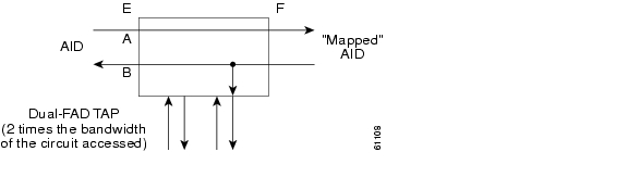
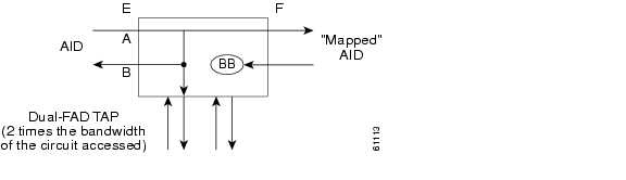
Figure 1-7 Split E (SPLTE) access
SPLTE indicates to split both the A and B paths and connect the E side of the accessed circuit to the FAD.
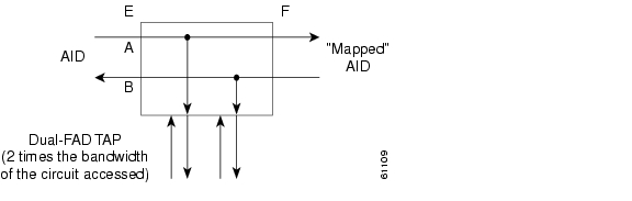
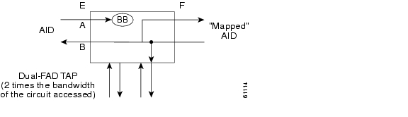
Figure 1-8 Split F (SPLTF) access
SPLTF indicates to split both the A and B paths and connect the F side of the accessed circuit to the FAD.
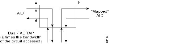
Figure 1-9 Split EF (SPLTEF) access
SPLTEF for T1 (DS1 HCDS) indicates to split both the A and B paths, connect the E side of the accessed circuit to FAD1 and the dual facility access digroup (DFAD) pair, and connect the F side to the FAD2 of the same DFAD pair. SPLTEF for T3 (DS3 HCDS) indicates to split both the A and B paths and connect the E side of the accessed circuit to the odd pair of the FAP and the F side to the even pair of the FAP.
1.8.3 Loop E and F Modes
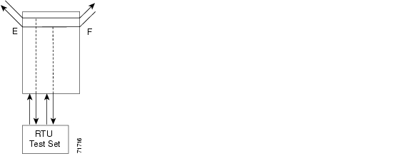
Loop E and F modes are basically identical to the SPLT E and F modes except that the outgoing signal is the incoming signal and not the signal from the remote test unit (RTU).
Figure 1-10 LOOPE access
LOOPE indicates to split both the A and B paths, connect the incoming line from the E direction to the outgoing line in the E direction, and connect this looped configuration to the FAD.
Figure 1-11 LOOPF access
LOOPF indicates to split both the A and B paths, connect the incoming line from the F direction to the outgoing line in the F direction and connect this looped configuration to the FAD.
1.8.4 Split A and B Access Modes
Split A and B access modes are shown in Figure 1-12 and Figure 1-13. These modes are similar to the Split E and F modes, except the signals are sent to the RTU, not the NE signal configuration.
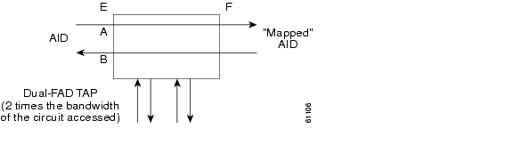
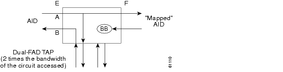
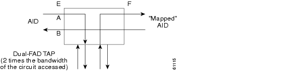
Figure 1-12 SPLTA access
SPLTA indicates that a connection is provided from both the E and F sides of the A transmission path of the circuit under test to the FAD and split the A transmission path.
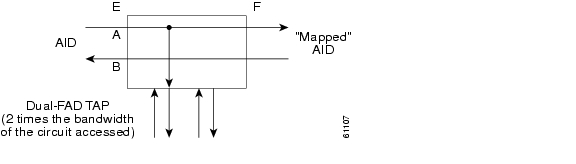
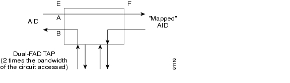
Figure 1-13 SPLTB access
SPLTB indicates that a connection is provided from both the E and F sides of the B transmission path of the circuit under test to the FAD and split the B transmission path.
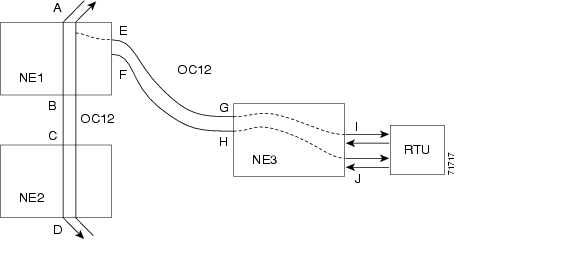
1.8.5 Creating Test Access Points
Figure 1-14 Multi-node view (MONE example)
Example 1-1 ED-STS1:NE1:STS-1-1:TACC=4;
This command creates a test access point (TAP) with STS-1-1 and STS-1-2 through NE1. The TAP number assigned is four.
1.8.6 Connecting Test Access Points
Note
Note
Example 1-2 ENT-CRS-STS1:NE3:<AID I-G>:100::2WAY;
This command is a connection, not a TAP. <CTAG> is 100.
Example 1-3 ENT-CRS-STS1:NE3:<AID J-H>:101::2WAY;
This command is a second connection, not a TAP.
Assuming the path from A to B is already entered, the A and B points in Figure 1-14 refer to entry and exit points on the node or different cards. The E/F designators refer to the two 2-way connections from NE3.
Example 1-4 CONN-TACC-STS1:NE1:<AID A or B>:102::4:<MONE>;
This command connects the TAP number four to the circuit.
The I and J connections would be TAPs in Figure 1-2, but normal connections in Figure 1-14. CTC will not present TAPs as parts of circuits. TAPs will be displayed on the node-level Maintenance/Test Access Tab. This tab helps to avoid confusion when a connection can be treated one way under TL1 but another way in CTC.
Note
1.8.7 Changing Test Access Modes
The command to change a TACC mode is:
Example 1-5 CHG-ACCMD-STS1:CISCO:8:123::MONF;
This command changes the test access mode for the circuit under test.This may be a change from monitoring the data to inserting data into the STS. This command can only be applied to an existing TAP connection. STS192c is not supported for Cisco ONS 15327.
1.8.8 Disconnecting Test Access Modes
TAPs can be disconnected in the following ways:
•
•
•
•
1.8.9 Deleting Test Access Points
The command to delete a TAP is:
Example 1-6 ED-<STS_PATH>:[<[TID>]:<AID>:<CTAG>:::TACC=0:;
Note
Note
![]()
![]()
![]()
![]()
![]()
![]()
![]()
![]()
Posted: Fri Feb 22 12:33:25 PST 2008
All contents are Copyright © 1992--2008 Cisco Systems, Inc. All rights reserved.
Important Notices and Privacy Statement.