|
|

Table Of Contents
4.2 ONS 15454 IP Addressing Scenarios
4.2.1 Scenario 1: CTC and ONS 15454s on Same Subnet
4.2.2 Scenario 2: CTC and ONS 15454s Connected to Router
4.2.3 Scenario 3: Using Proxy ARP to Enable an ONS 15454 Gateway
4.2.4 Scenario 4: Default Gateway on CTC Computer
4.2.5 Scenario 5: Using Static Routes to Connect to LANs
4.2.6 Scenario 6: Static Route for Multiple CTCs
4.3 Viewing the ONS 15454 Routing Table
IP Networking
This chapter explains how to set up Cisco ONS 15454s in internet protocol (IP) networks and includes:
•
Scenarios showing Cisco ONS 15454s in common IP network configurations
•
•
The chapter does not provide a comprehensive explanation of IP networking concepts and procedures.
Note
4.1 IP Networking Overview
ONS 15454s can be connected in many different ways within an IP environment:
•
•
•
•
•
4.2 ONS 15454 IP Addressing Scenarios
ONS 15454 IP addressing generally has seven common scenarios or configurations. Use the scenarios as building blocks for more complex network configurations. Table 4-1 provides a general list of items to check when setting up ONS 15454s in IP networks. Additional procedures for troubleshooting Ethernet connections and IP networks are provided in Chapter 9, "Ethernet Operation."
Table 4-1 General ONS 15454 IP Networking Checklist
PC/workstation
Each CTC computer must have the following:
•
•
•
See the "Computer Requirements" section on page 2-2 for additional information.
Link integrity
Link integrity exists between:
•
•
•
ONS 15454 hub/switch ports
Set the hub or switch port that is connected to the ONS 15454 to 10 Mbps half-duplex.
Ping
Ping the node to test connections between computers and ONS 15454s.
IP addresses/subnet masks
ONS 15454 IP addresses and subnet masks are set up correctly.
Optical connectivity
ONS 15454 optical trunk ports are in service; DCC is enabled on each trunk port
4.2.1 Scenario 1: CTC and ONS 15454s on Same Subnet
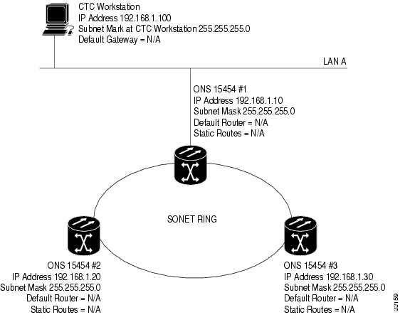
Scenario 1 shows a basic ONS 15454 LAN configuration ( Figure 4-1). The ONS 15454s and CTC computer reside on the same subnet. All ONS 15454s connect to LAN A, and all ONS 15454s have DCC connections.
Note
Figure 4-1 Scenario 1: CTC and ONS 15454s on same subnet
4.2.2 Scenario 2: CTC and ONS 15454s Connected to Router
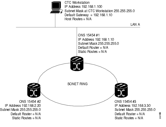
In Scenario 2 the CTC computer resides on a subnet (192.168.1.0) and attaches to LAN A ( Figure 4-2). The ONS 15454s reside on a different subnet (192.168.2.0) and attach to LAN B. A router connects LAN A to LAN B. The IP address of router interface A is set to LAN A (192.168.1.1), and the IP address of router interface B is set to LAN B (192.168.2.1).
On the CTC computer, the default gateway is set to router interface A. If the LAN uses DHCP (Dynamic Host Configuration Protocol), the default gateway and IP address are assigned automatically. In the Figure 4-2 example, a DHCP server is not available.
Figure 4-2 Scenario 2: CTC and ONS 15454s connected to router
4.2.3 Scenario 3: Using Proxy ARP to Enable an ONS 15454 Gateway
Scenario 3 is similar to Scenario 1, but only one ONS 15454 (node #1) connects to the LAN ( Figure 4-3). Two ONS 15454s (#2 and #3) connect to ONS 15454 #1 through the SONET DCC. Because all three ONS 15454s are on the same subnet, Proxy ARP enables ONS 15454 #1 to serve as a gateway for ONS 15454s #2 and #3.
Figure 4-3 Scenario 3: Using Proxy ARP
ARP matches higher-level IP addresses to the physical addresses of the destination host. It uses a lookup table (called ARP cache) to perform the translation. When the address is not found in the ARP cache, a broadcast is sent out on the network with a special format called the ARP request. If one of the machines on the network recognizes its own IP address in the request, it sends an ARP reply back to the requesting host. The reply contains the physical hardware address of the receiving host. The requesting host stores this address in its ARP cache so that all subsequent datagrams (packets) to this destination IP address can be translated to a physical address.
Proxy ARP enables one LAN-connected ONS 15454 to respond to the ARP request for ONS 15454s not connected to the LAN. (ONS 15454 Proxy ARP requires no user configuration.) For this to occur, the DCC-connected ONS 15454s must reside on the same subnet. When a LAN device sends an ARP request to an ONS 15454 that is not connected to the LAN, the gateway ONS 15454 returns its MAC address to the LAN device. The LAN device then sends the datagram for the remote ONS 15454 to the MAC address of the proxy ONS 15454. The proxy ONS 15454 uses its routing table to forward the datagram to the non-LAN ONS 15454. The routing table is built using the OSPF IP routing protocol. (An OSPF example is presented in Scenario 6.)
4.2.4 Scenario 4: Default Gateway on CTC Computer
Scenario 4 is similar to Scenario 3, but nodes #2 and #3 reside on different subnets, 192.168.2.0 and 192.168.3.0, respectively ( Figure 4-4). Node #1 and the CTC computer are on subnet 192.168.1.0. The network includes different subnets because Proxy ARP is not used. In order for the CTC computer to communicate with ONS 15454s #2 and #3, ONS 15454 #1 is entered as the default gateway on the CTC computer using the "Direct Connections to the ONS 15454" section on page 2-5.
Figure 4-4 Scenario 4: Default gateway on a CTC computer
4.2.5 Scenario 5: Using Static Routes to Connect to LANs
Static routes are used for two purposes:
•
•
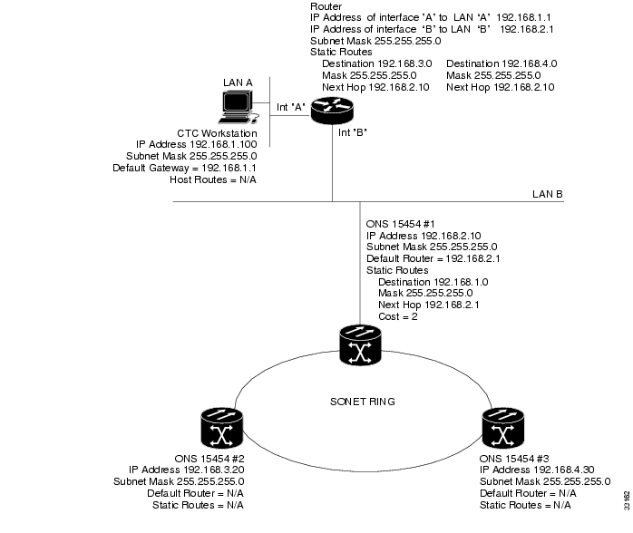
In Figure 4-5, one CTC residing on subnet 192.168.1.0 connects to a router through interface A. (The router is not set up with OSPF.) ONS 15454s residing on subnet 192.168.2.0 are connected through ONS 15454 #1 to the router through interface B. Proxy ARP enables ONS 15454 #1 as a gateway for ONS 15454s #2 and #3. To connect to CTC computers on LAN A, a static route is created on ONS 15454 #1.
Figure 4-5 Scenario 5: Static route with one CTC computer used as a destination
The destination and subnet mask entries control access to the ONS 15454s:
•
•
•
The IP address of router interface B is entered as the next hop, and the cost (number of hops from source to destination) is 2.
Figure 4-6 Scenario 5: Static route with multiple LAN destinations
Procedure: Create a Static Route
Use the following steps to create a static route.
Step 1
Step 2
Step 3
•
•
•
•
Step 4
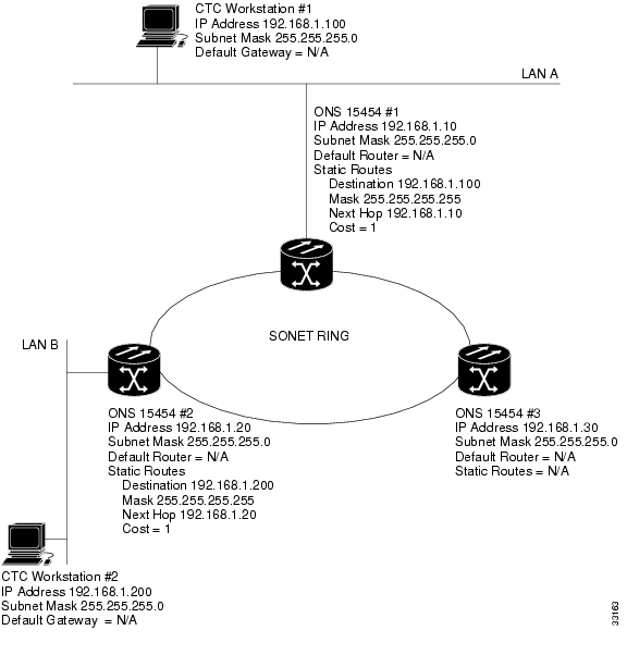
4.2.6 Scenario 6: Static Route for Multiple CTCs
Scenario 6 shows a static route used when multiple CTC computers need to access ONS 15454s residing on the same subnet ( Figure 4-7). In this scenario, CTC #1 and #2 and all ONS 15454s are on the same IP subnet; ONS 15454 #1 and CTC #1 are attached to LAN A. ONS 15454 #2 and CTC #2 are attached to LAN B. Static routes are added to ONS 15454 #1 pointing to CTC #1, and to ONS 15454 #2 pointing to CTC #2. The static route is entered from the node's perspective.
Figure 4-7 Scenario 6: Static route for multiple CTCs
4.2.7 Scenario 7: Using OSPF
Open Shortest Path First (OSPF) is a link state Internet routing protocol. Link state protocols use a "hello protocol" to monitor their links with adjacent routers and to test the status of their links to their neighbors. Link state protocols advertise their directly-connected networks and their active links. Each link state router captures the link state "advertisements" and puts them together to create a topology of the entire network or area. From this database, the router calculates a routing table by constructing a shortest path tree. Routes are continuously recalculated to capture ongoing topology changes.
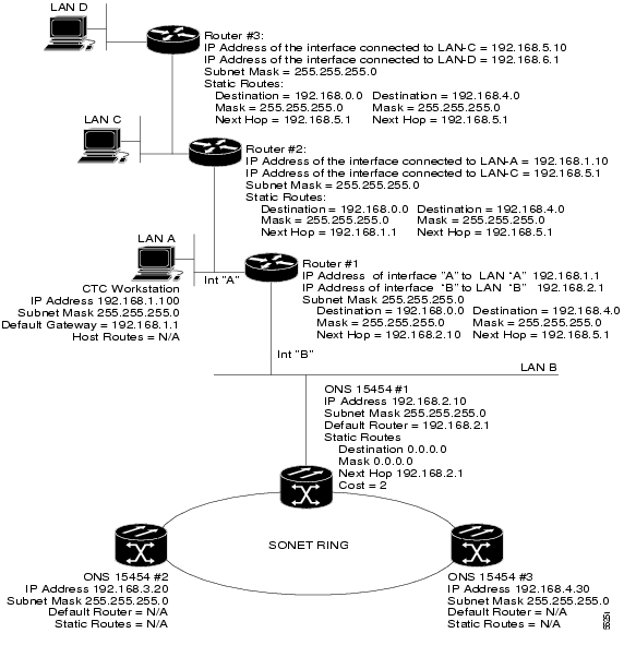
ONS 15454s use the OSPF protocol in internal ONS 15454 networks for node discovery, circuit routing, and node management. You can enable OSPF on the ONS 15454s so that the ONS 15454 topology is sent to OSPF routers on a LAN. Advertising the ONS 15454 network topology to LAN routers eliminates the need to manually enter static routes for ONS 15454 subnetworks. Figure 4-8 shows the same network enabled for OSPF. Figure 4-9 shows the same network without OSPF. Static routes must be manually added to the router in order for CTC computers on LAN A to communicate with ONS 15454 #2 and #3 because these nodes reside on different subnets.
OSPF divides networks into smaller regions, called areas. An area is a collection of networked end systems, routers, and transmission facilities organized by traffic patterns. Each OSPF area has a unique ID number, known as the area ID, that can range from 0 to 4,294,967,295. Every OSPF network has one backbone area called "area 0." All other OSPF areas must connect to area 0.
When you enable ONS 15454 OSPF topology for advertising to an OSPF network, you must assign an OSPF area ID to the ONS 15454 network. Coordinate the area ID number assignment with your LAN administrator. In general, all DCC-connected ONS 15454s are assigned the same OSPF area ID.
Figure 4-8 Scenario 7: OSPF enabled
Figure 4-9 Scenario 7: OSPF not enabled
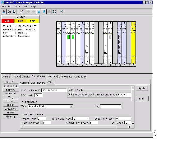
Use the following procedure to enable OSPF on each ONS 15454 node that you want included in the OSPF network topology. ONS 15454 OSPF settings must match the router OSPF settings, so you will need to get the OSPF Area ID, Hello and Dead intervals, and authentication key (if OSPF authentication is enabled) from the router to which the ONS 15454 network is connected before enabling OSPF.
Procedure: Set up OSPF
Step 1
Step 2
Figure 4-10 Enabling OSPF on the ONS 15454
Step 3
•
•
Step 4
•
•
Step 5
•
•
Step 6
The OSPF priority and intervals default to values most commonly used by OSPF routers. In the Priority and Invervals area, verify that these values match those used by the OSPF router where the ONS 15454 is connected.
•
•
•
•
•
•
Step 7
Area range tables consolidate the information that is propagated outside an OSPF Area border. One ONS 15454 in the ONS 15454 OSPF area is connected to the OSPF router. An area range table on this node points the router to the other nodes that reside within the ONS 15454 OSPF area.
To create an area range table:
a.
b.
–
–
–
–
c.
Step 8
a.
b.
Neighbor—Enter the router ID of the Area 0 router.
Transit Delay (sec)—The service speed. One second is the default.
Hello Int (sec)—The number of seconds between OSPF "hello" packet advertisements sent by OSPF routers. Ten seconds is the default.
Auth Type—If the router where the ONS 15454 is connected uses authentication, select Simple Password. Otherwise, set it to No Authentication.
Retransmit Int (sec)—Sets the time that will elapse before a packet is resent. Five seconds is the default.
Dead Int (sec)—Sets the number of seconds that will pass while an OSPF router's packets are not visible before its neighbors declare the router down. Forty seconds is the default.
c.
Step 9
If you changed the Area ID, the TCC+ cards will reset, one at a time.
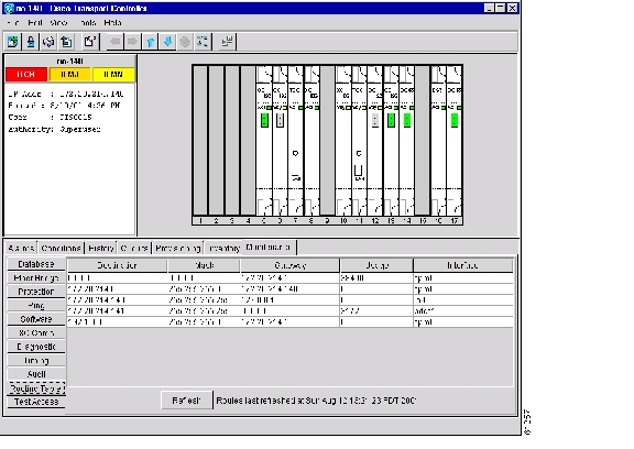
4.3 Viewing the ONS 15454 Routing Table
ONS 15454 routing information is displayed on the Maintenance > Routing Table tabs ( Figure 4-11). The routing table provides the following information:
•
•
•
•
•
–
–
–
Figure 4-11 Viewing the ONS 15454 routing table
Table 4-2 shows sample routing entries for an ONS 15454.
Entry #1 shows the following:
•
•
•
•
Entry #2 shows the following:
•
•
•
•
Entry #3 shows the following:
•
•
•
•
Entry #4 shows the following:
•
•
•
•
Entry #5 shows a DCC-connected node that is accessible through a node that is not directly connected:
•
•
•
•
![]()
![]()
![]()
![]()
![]()
![]()
![]()
![]()
Posted: Fri Feb 22 15:26:46 PST 2008
All contents are Copyright © 1992--2008 Cisco Systems, Inc. All rights reserved.
Important Notices and Privacy Statement.