|
|

Table Of Contents
2.3 Running the CTC Setup Wizard
2.4 Connecting PCs to the ONS 15454
2.4.1 Direct Connections to the ONS 15454
2.4.3 Remote Access to the ONS 15454
2.4.4 TL1 Terminal Access to the ONS 15454
2.5 Logging into the ONS 15454
2.5.1 Creating Login Node Groups
2.5.2 Accessing ONS 15454s Behind Firewalls
2.6 Working with the CTC Window
2.9 Printing and Exporting CTC Data
2.10 Displaying CTC Data in Other Applications
Software Installation
Cisco Transport Controller (CTC), the Cisco ONS 15454's software interface, is stored on the TCC+ card and downloads to your workstation each time you log into the ONS 15454. This chapter:
•
Describes how Cisco Transport Controller (CTC) software is installed on PCs and Solaris workstations
•
•
•
•
•
2.1 Installation Overview
ONS 15454 provisioning and administration is performed using the Cisco Transport Controller software. CTC is a Java application that is installed in two locations:
•
•
CTC software is pre-installed on the TCC+. The only time you install software on the TCC+ is when you upgrade from one CTC release to another. To upgrade CTC on the TCC+, you must follow the upgrade procedures specific to the software release. These procedures can be downloaded from the Cisco website (www.cisco.com).
For PCs and Solaris workstations, CTC is downloaded from the TCC+ and installed on your computer automatically after you connect to the ONS 15454. To connect to an ONS 15454, you enter the ONS 15454 IP address in the URL field of a web browser, such as Netscape Navigator or Microsoft° Internet Explorer. After connecting to an ONS 15454, the following installation occurs automatically:
1.
2.
3.
4.
Each ONS 15454 can handle up to four network-level CTC sessions (the login node and its DCC-connected nodes) and one node-level session (login node only) at one time. CTC performance may vary, depending upon the volume of activity in each session.
Note
2.2 Computer Requirements
To use CTC in ONS 15454 Release 3.2, your computer must have a web browser with the correct Java Runtime Environment (JRE) installed. The correct JRE for each CTC software release is included on the Cisco ONS 15454 ONS 15454 software CD. If you are running multiple CTC software releases on a network, the JRE installed on your computer must be compatible with the different software releases. Table 2-1 shows JRE compatibility with ONS software releases.
Requirements for PCs and Solaris workstations are provided in Table 2-2. A modified java.policy file must also be installed. In addition to Netscape Communicator and the JRE, also included on the ONS 15454 software CD and the ONS 15454 documentation CD are the Java plug-in and modified java.policy file.
Note
2.3 Running the CTC Setup Wizard
The ONS 15454 provides a setup wizard that installs the files needed to run CTC on PCs and Solaris workstations. You can run the setup wizard from the Cisco ONS 15454 software CD or from the Cisco ONS 15454 documentation CD. The wizard will install:
•
•
•
•
For Solaris workstations, the JRE may require patches to run properly. You can find the patch tar file in the Jre/Solaris directory on the CD. For information about installing the patches, see the Jre/Solaris/Solaris.txt file on the CD. After installing the patches, if necessary, perform the "Set Up the Environment Variable (Solaris installations only)" procedure and the "Reference the JRE (Solaris installations only)" procedure to set up JRE on the workstation.
Procedure: Run the CTC Setup Wizard
Step 1
Step 2
Step 3
Procedure: Set Up the Environment Variable (Solaris installations only)
Perform one of the following edit procedures. (JRE indicates the destination directory you selected for the JRE.)
•
setenv NPX_PLUGIN_PATH [JRE]/j2rel1_3_0_01/plugin/sparc/ns4
•
export NPX_PLUGIN_PATH = [JRE]/j2rel1_3_0_01/plugin/sparc/ns4
Procedure: Reference the JRE (Solaris installations only)
Step 1
[JRE]/j2rel1_3_0_01/bin/ControlPanel
Step 2
Step 3
[JRE]/j2rel1_3_0_01
Step 4
2.4 Connecting PCs to the ONS 15454
You can connect a PC to the ONS 15454 using the RJ-45 LAN port on the TCC+ or the LAN 1 pins on the ONS 15454 backplane. For a list of LAN pin assignments, see Table 1-2 on page 1-33. Each ONS 15454 must have a unique IP address that you use to access the ONS 15454. The address is displayed on the front panel LCD. The initial IP address, 192.1.0.2, is the default address for ONS 15454 access and configuration. Each computer used to communicate with the ONS 15454 should have only one IP address.
Note
2.4.1 Direct Connections to the ONS 15454
A direct PC to ONS 15454 connection means your computer is physically connected to the ONS 15454. This is most commonly done by connecting a CAT-5 straight-through cable from your PC NIC card to the RJ-45 port on the TCC+ card. (Direct connections include connections to switches or hubs to which the ONS 15454 is physically connected.) To connect to the ONS 15454 with a direct connection, you must:
•
•
•
Procedure: Creating a Direct Connection to an ONS 15454
Step 1
•
•
Step 2
•
•
Step 3
a.
b.
c.
d.
ping [ONS 15454 IP address]
For example, you would type "ping 192.1.0.2" to connect to an ONS 15454 with default IP address 192.1.0.2. If your computer is connected to the ONS 15454, a "reply from [IP address]" message displays.
If your PC is not connected, a Request timed out message displays. If this occurs, check that the cables connecting the PC to the ONS 15454 are securely attached. Check the Link Status LED on the PC NIC card. Repeat the procedures provided in Table 2-3 while verifying IP and submask information.
2.4.2 Network Connections
When connecting the PC to the ONS 15454 through a LAN, the PC's IP address must be configured to be on the same subnet as the ONS 15454's LAN interface. The ONS 15454 IP address and netmask are visible on the LCD panel. If needed, change the IP address configuration on the PC or use the LCD panel on the ONS 15454.
Procedure: Access the ONS 15454 from a LAN
Step 1
Step 2
Step 3
Step 4
Step 5
Procedure: Disable Proxy Service Using Internet Explorer (Windows)
Complete these steps if your computer is connected to a proxy server and your browser is Internet Explorer.
Step 1
Step 2
Step 3
Step 4
•
or
•
Procedure: Disable Proxy Service Using Netscape (Windows and Solaris)
Complete these steps if your computer is connected to a proxy server and your browser is Netscape Navigator.
Step 1
Step 2
Step 3
Step 4
•
or
•
2.4.3 Remote Access to the ONS 15454
You can use LAN modems to access ONS 15454s from remote sites. The LAN modem must be connected to the RJ-45 port on a TCC+ card or to the LAN pins on the ONS 15454 backplane. The LAN modem must be properly configured for use with the ONS 15454. When the modem is installed, dial-up access to the ONS 15454 is available using a PC or Solaris workstation modem.
2.4.4 TL1 Terminal Access to the ONS 15454
You can communicate with the ONS 15454 using TL1. To connect a TL1 terminal (or a PC running terminal emulation software) to the ONS 15454, you can:
•
•
•
For information about using TL1 commands with the ONS 15454, see the Cisco ONS 15454 TL1 Command Guide.
2.5 Logging into the ONS 15454
After you set up the physical connections between the PC and ONS 15454 and change your PC network settings, you can log into CTC.
Note
Procedure: Log into the ONS 15454
Step 1
Step 2
Note
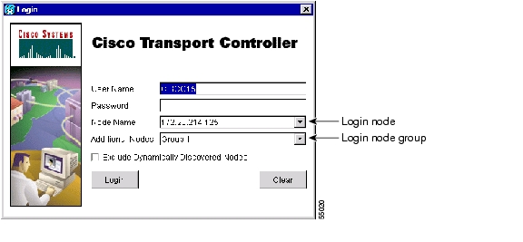
A Java Console window displays the CTC file download status. The web browser displays information about your Java and system environments. If this is the first login, CTC caching messages display while CTC files are downloaded to your computer; then the CTC Login dialog box displays ( Figure 2-1).
Figure 2-1 Logging into the ONS 15454
Step 3
Note
Step 4
•
•
Note
•
Step 5
If login is successful, the CTC window displays. From here, you can navigate to other CTC views to provision and manage the ONS 15454.
2.5.1 Creating Login Node Groups
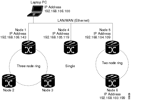
When you log into an ONS 15454 node, only ONS 15454s optically connected (i.e., with DCC connections) to the node will display in network view. However, you can create a login node group to view and manage ONS 15454s that only have an IP connection. For example, logging into Node 1 in Figure 2-2 displays Node 2 and Node 3 because they are optically connected to Node 1. Nodes 4, 5, and 6 do not display because DCC connections do not exist. To view all six nodes at once, you create a login node group with the IP addresses of Nodes 1, 4, and 5. Those nodes, and all nodes optically connected to them, display when you log into any node in the group.
Caution
Figure 2-2 A login node group
Procedure: Create a Login Node Group
Step 1
Step 2
Step 3
Step 4
Step 5
The next time you log into an ONS 15454, the login node group will be available in the Additional Nodes list of the Login dialog box. You can create as many login groups as you need. The groups are stored in the CTC preferences file and are not visible to other users.
2.5.2 Accessing ONS 15454s Behind Firewalls
If an ONS 15454 or CTC computer resides behind a firewall that uses port filtering, you must receive an Internet Inter-ORB Protocol (IIOP) port from your network administrator and enable the IIOP port on the ONS 15454 and/or CTC computer, depending on whether one or both devices reside behind firewalls.
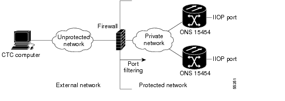
If the ONS 15454 is in a protected network and the CTC computer is in an external network, as shown in Figure 2-3, enable the IIOP listener port specified by the firewall administrator on the ONS 15454. The ONS 15454 sends the port number to the CTC computer during the initial contact between the devices using Hyper-Text Transfer Protocol (HTTP). After the CTC computer obtains the ONS 15454 IIOP port, the computer opens a direct session with the node using the specified IIOP port.
Figure 2-3 ONS 15454s residing behind a firewall
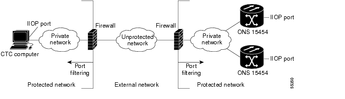
If the CTC computer and the ONS 15454 both reside behind firewalls ( Figure 2-4), set the IIOP port on the CTC computer and on the ONS 15454. Each firewall can use a different IIOP port. For example, if the CTC computer firewall uses IIOP port 4000, and the ONS 15454 firewall uses IIOP port 5000, 4000 is the IIOP port set on the CTC computer and 5000 is the IIOP port set on the ONS 15454.
Figure 2-4 A CTC computer and ONS 15454s residing behind firewalls
Procedure: Set the IIOP Listener Port on the ONS 15454
Step 1
Step 2
Step 3
•
•
•
Step 4
Step 5
Both ONS 15454 TCC+s will reboot, one at a time.
Procedure: Set the IIOP Listener Port on CTC
Step 1
Step 2
Step 3
•
•
•
Step 4
2.6 Working with the CTC Window
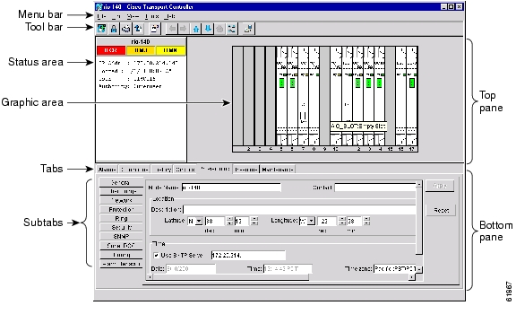
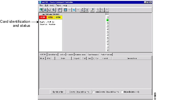
The CTC window (screen) displays after you log into an ONS 15454 ( Figure 2-5). The window includes a menu bar, toolbar, and a top and bottom pane. The top pane displays status information about the selected objects and a graphic of the current view. The bottom pane displays tabs and subtabs, which you use to view ONS 15454 information and perform ONS 15454 provisioning and maintenance. From this window you can display three ONS 15454 views: network, node, and card.
Figure 2-5 CTC window elements in the node view (default login view)
2.6.1 Node View
The CTC node view, shown in Figure 2-5, is the first view displayed after you log into an ONS 15454. The login node is the first node displayed, and it is the "home view" for the session. Node view allows you to view and manage one ONS 15454 node. The status area shows the node name, IP address, session boot date and time, number of critical (CR), major (MJ), and minor (MN) alarms, the name of the current logged-in user, and security level of the user.
2.6.1.1 CTC Card Colors
The graphic area of the CTC window depicts the ONS 15454 shelf assembly. The colors of the cards in the graphic reflect the real-time status of the physical card and slot ( Table 2-4).
2.6.1.2 Node View Card Shortcuts
If you move your mouse over cards in the graphic, tooltips display additional information about the card including the card type, card status (active or standby), the number of critical, major, and minor alarms (if any), and the alarm profile used by the card. Right-clicking a card reveals a shortcut menu, which you can use to open, reset, or delete a card. Right-click a slot (grey) to pre-provision a card (i.e., provision a slot before installing the card).
2.6.1.3 Node View Tabs
Use the node view tabs and subtabs, shown in Table 2-5, to provision and manage the ONS 15454.
2.6.2 Network View
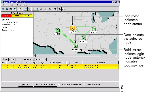
Network view ( Figure 2-6) allows you to view and manage ONS 15454s and ONS 15327s that have DCC connections to the node that you logged into and any login node groups you may have selected. (Nodes with DCC connections to the login node will not display if you selected Exclude Dynamically Discovered Nodes on the Login dialog box.) The graphic area displays a background image with colored ONS 15454 icons. The icon colors indicate the node status ( Table 2-6). Green lines show DCC connections between the nodes. Selecting a node or span in the graphic area displays information about the node and span in the status area.
Figure 2-6 A four-node network displayed in CTC network view
2.6.2.1 CTC Node Colors
The colors of nodes displayed in network view indicate the status of the node.
2.6.2.2 Network View Tasks
Right-click the network view graphic area or a node, span, or domain (domains are described in the "Creating Domains" section) to display shortcut menus. Table 2-7 lists the actions that are available from the network view.
Table 2-7 Performing Network Management Tasks in Network View
Open a node
Any of the following:
•
•
•
•
•
Move a node icon
Press the Ctrl key and the left mouse button simultaneously and drag the node icon to a new location.
Reset node icon position
Right-click a node and choose Reset Node Position from the shortcut menu. The node icon moves to the position defined by the longitude and latitude fields on the Provisioning > General tabs in node view.
Provision a circuit
Right-click a node. From the shortcut menu, choose Provision Circuit To and select the node where you want to provision the circuit. For circuit creation procedures, see the "Create an Automatically Routed Circuit" procedure.
Update circuits with new node
Right-click a node and choose Update Circuits With New Node from the shortcut menu. Use this command when you add a new node and want to pass circuits through it.
Display a link end point
Right-click a span. On the shortcut menu, select Go To [node/slot/port] for the drop port you want to view. CTC displays the card in card view.
Display span properties
Any of the following:
•
•
•
Perform a UPSR protection switch for an entire span
Right-click a network span and click Circuits. See the "Switch UPSR Traffic" procedure for UPSR protection switch procedures.
Upgrade a span
Right-click a span and choose Upgrade Span from the shortcut menu.
Note
2.6.2.3 Creating Domains
Domains are icons where you can add a group of ONS 15454s or ONS 15327s. Adding domains to the network view map makes networks with many nodes easier to manage. After you create a domain, you can drag and drop ONS 15454 icons into it ( Figure 2-7). The ONS 15454s are hidden until you open the domain. Figure 2-9 shows an example of an opened domain.
Figure 2-7 Adding nodes to a domain
After you add a node to a domain, the span lines leading to nodes within the domain become thicker ( Figure 2-8). The thick lines may represent multiple spans. For example, if the "rio-104" node in Figure 2-8 is connected to two nodes within domain-0, the thick line represents two spans. The thick line is green if all spans it represents are active and grey if any one span it represents is down. The domain icon color reflects the highest alarm severity of any node within it.
Figure 2-8 Outside nodes displayed within the domain
Within the domain, external nodes and domains that are directly connected to nodes inside the domain are displayed in a dimmed color ( Figure 2-9). DCC links with one or two ends inside the domain are also displayed.
Figure 2-9 Nodes inside a domain
You manage ONS 15454s that reside within a domain the same way you manage ONS 15454s on the network map. Table 2-8 shows the domain actions.
Note
2.6.2.4 Changing the Network View Background Color
You can change the color of the network view background and the domain view background (the area displayed when you open a domain). If you modify background colors, the change is stored in your CTC user profile on the computer. The change does not affect other CTC users.
Procedure: Modify the Network View or Domain Background Color
Step 1
Step 2
Step 3
2.6.2.5 Changing the Network View Background Image
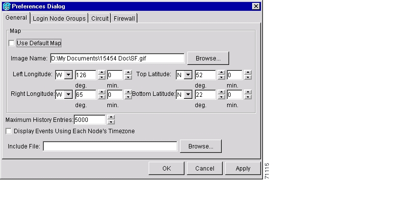
You can replace the background map image displayed in network view with any JPEG or GIF image that is accessible on a local or network drive. If you want to position nodes on the map based on the node coordinates, you will need the longitudes and latitudes for the edges of the map. However, if you will use your mouse to position nodes, coordinates for the image edges are not necessary. The change does not affect other CTC users.
Note
Procedure: Change the Network View Background Image
Caution
Step 1
Step 2
Figure 2-10 Changing the CTC background image
Step 3
Step 4
Step 5
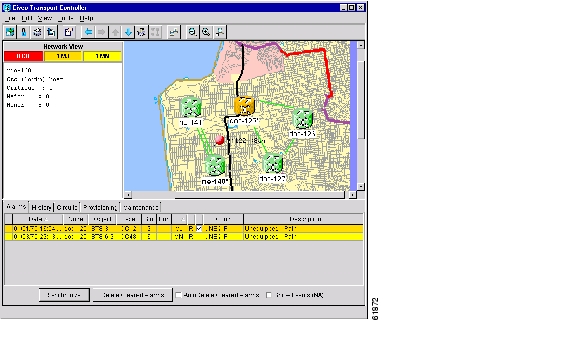
Step 6
Figure 2-11 The network view with a custom map image
Step 7
Procedure: Add a Node to the Current Session
During a CTC session, you can add nodes that are not displayed in the session without having to log out of the session. When you add the node, you have the option to add it to the current login node group.
Step 1
Step 2
Step 3
Step 4
After a few seconds, the new node will be displayed on the network view map.
2.6.3 Card View
Card view displays information about individual ONS 15454 cards and is the window where you perform card-specific maintenance and provisioning ( Figure 2-12). A graphic of the selected card is shown in the graphic area. The status area displays the node name, slot, number of alarms, card type, equipment type, and either the card status (active or standby) or port status (IS [in service] or OOS [out of service]). The information that is displayed and the actions you can perform depend on the card.
Note
Card view provides access to the following tabs: Alarms, History, Circuits, Provisioning, Maintenance, Performance, and Conditions. (The Performance tab is not displayed for the AIC card.) The subtabs, fields, and information displayed under each tab depend on the card type selected.
Figure 2-12 CTC card view showing an DS3N-12 card
2.7 CTC Navigation
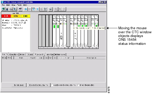
Different navigational methods are available within the CTC window to access views and perform management actions. Commands on the View menu and CTC toolbar allow you to quickly move between network, node, and card views. You can double-click and right-click objects in the graphic area and move the mouse over nodes, cards, and ports to view popup status information. Figure 2-13 shows an example.
Figure 2-13 CTC node view showing popup information
Table 2-9 describes different methods for navigating within the CTC window.
2.8 Viewing CTC Table Data
Much of the ONS 15454 data that CTC displays, such as alarms, alarm history, circuits, and inventory, is displayed in tables. You can change the way the CTC tables are displayed. For example, you can:
•
•
•
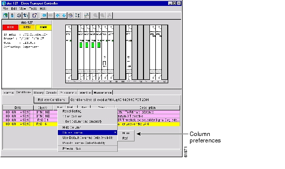
To change the display of a CTC table, left-click or right-click a column header in the table. Right-click a column header to display a shortcut menu that has table column display options ( Figure 2-14).
Figure 2-14 Table shortcut menu that customizes table appearance
Table 2-10 lists the options that you can use to customize information that is displayed in CTC tables.
2.9 Printing and Exporting CTC Data
You can print CTC windows and table data such as alarms and inventory. You can also export CTC table data for use by other applications such as spreadsheets, word processors, and database management applications. Table 2-11 shows CTC data that can be exported.
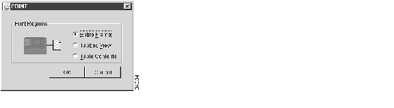
Procedure: Print CTC Window and Table Data
Use the following procedure to print CTC windows and table data. Before you start, make sure your PC is connected to a printer.
Step 1
Step 2
•
•
•
Figure 2-15 Selecting CTC data for print
Step 3
Step 4
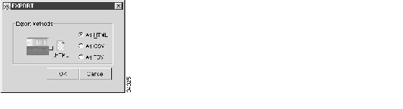
Procedure: Export CTC Data
Step 1
Step 2
•
•
•
Figure 2-16 Selecting CTC data for export
Step 3
Step 4
•
•
•
Step 5
Step 6
2.10 Displaying CTC Data in Other Applications
CTC data exported in HTML format can be viewed with any web browser, such as Netscape Navigator or Microsoft Internet Explorer. To display the data, use the browser's File/Open command to open the CTC data file.
CTC data exported as comma separated values (CSV) or tab separated values (TSV) can be viewed in text editors, word processors, spreadsheets, and database management applications. Although procedures depend on the application, you typically can use File/Open to display the CTC data. Text editors and word processors display the data exactly as it is exported. Spreadsheet and database management applications display the data in cells. You can then format and manage the data using the spreadsheet or database management application tools.
In addition to the CTC exporting, CTC text information can be copied and pasted into other applications using the Windows Copy (Ctrl+C), Cut (Ctrl+X) and Paste (Ctrl+V) commands.
![]()
![]()
![]()
![]()
![]()
![]()
![]()
![]()
Posted: Fri Feb 22 15:40:51 PST 2008
All contents are Copyright © 1992--2008 Cisco Systems, Inc. All rights reserved.
Important Notices and Privacy Statement.