|
|

Table Of Contents
2.2.3 Using the DS3XM-6 Card FEAC (Loopback) Functions
2.3 CTC Operation and Connectivity
2.3.1 Browser Stalls When Downloading jar File From TCC+
2.3.2 Browser Cache Points to an Invalid Directory
2.3.3 Clear the CTC Cache File
2.3.4 Node Icon is Grey on CTC Network View
2.3.5 CTC Cannot Launch Due to Applet Security Restrictions
2.3.6 Java Runtime Environment Incompatible
2.3.7 Different CTC Releases Do Not Recognize Each Other
2.3.8 Username or Password Do Not Match
2.3.9 No IP Connectivity Exists Between Nodes
2.3.11 Browser Login Does not Launch Java
2.3.12 Verify PC Connection to ONS 15454 (ping)
2.3.13 Calculate and Design IP Subnets
2.3.15 VLAN Cannot Connect to Network Device from Untag Port
2.4.1 AIS-V on DS3XM-6 Unused VT Circuits
2.4.2 Circuit Creation Error with VT1.5 Circuit
2.4.3 Unable to Create Circuit From DS-3 Card to DS3XM-6 Card
2.4.4 DS3 Card Does Not Report AIS-P From External Equipment
2.4.5 OC-3 and DCC Limitations
2.4.6 ONS 15454 Switches Timing Reference
2.4.7 Holdover Synchronization Alarm
2.4.8 Free-Running Synchronization Mode
2.4.9 Daisy-Chained BITS Not Functioning
2.5.1 Bit Errors Appear for a Line Card
2.5.2 Faulty Fiber-Optic Connections
2.5.4 Optical Card Transmit and Receive Levels
2.6.2 Power Consumption for Node and Cards
General Troubleshooting
This chapter provides solutions for the most common problems encountered when operating a Cisco ONS 15454. To troubleshoot specific ONS 15454 alarms, use Chapter 1, "Alarm Troubleshooting." The Problem List is an alphabetized list of the chapter's procedures and their page numbers. The problem areas are grouped by topic; if you cannot find what you are looking for in this chapter or Chapter 1, "Alarm Troubleshooting," contact the Cisco Technical Assistance Center (TAC) at 1-877-323-7368.
2.1 Problem List
Table 2-1 Type of Problem and Solution Location
2.2 Network Tests
Use loopbacks and hairpins to test newly-created circuits before adding live traffic or to logically isolate the source of a network failure. All ONS 15454 line (traffic) cards, except Ethernet cards, allow loopbacks and hairpins.
2.2.1 Network Test Types
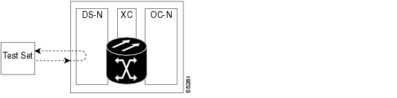
Facility loopbacks test the line interface unit (LIU) of a card, the EIA (electrical interface assembly), and cabling. You put a facility loopback on a card and use a test set to run traffic over the loopback. A successful facility loopback eliminates the LIU of the card, the EIA, or cabling plant as the cause or potential cause of a network problem. Figure 2-1 shows a facility loopback on a DS-N card.
Figure 2-1 The facility loopback process on a DS-N card
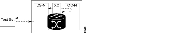
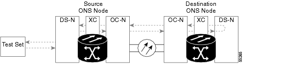
Terminal loopbacks test a circuit path through the cross-connect card and as it loops back from the line card being tested. Figure 2-2 shows a terminal loopback set on an OC-N card. The test set traffic comes in on the DS-N card and goes through the cross-connect card to the OC-N card. The terminal loopback on the OC-N card turns the signal around before it reaches the LIU and sends it through the cross-connect card to the DS-N card. This test verifies that the cross-connect card and circuit paths are valid, but does not test the LIU on the OC-N card. To test the LIU on an OC-N card, connect an optical test set to the OC-N card ports and perform a facility loopback or use a loopback or hairpin on a card that is farther along the circuit path.
Figure 2-2 The terminal loopback process on an OC-N card
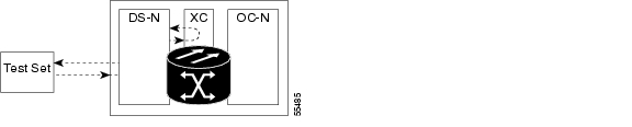
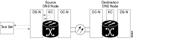
Hairpin circuits bring traffic in and out on a DS-N port instead of sending the traffic onto the OC-N. A hairpin loops back only the specific STS or VT circuit and does not cause an entire OC-N port to loop back, which would drop all traffic on the OC-N port. The hairpin allows you to test a circuit on nodes running live traffic.
Figure 2-3 The hairpin circuit process on an OC-N card
2.2.2 Network Test Procedures
Facility loopbacks, terminal loopbacks, and hairpin circuits are often used together to test the circuit path through the network or to logically isolate a fault. Performing a network test at each point along the circuit path systematically eliminates possible points of failure. This example tests a DS-N circuit on a two-node bidirectional line switched ring (BLSR). Using a series of facility loopbacks, terminal loopbacks, and hairpins, the path of the circuit is traced and the possible points of failure eliminated.
A logical progression of five network test procedures apply to this scenario: a facility loopback on the source node DS-N card, a hairpin on the source node DS-N card, a hairpin on the destination node OC-N card, a terminal loopback to the destination node DS-N card, and a facility loopback to the destination DS-N card.
Procedure: Perform a Facility Loopback on a Source DS-N Card
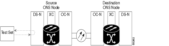
The first loopback test is a facility test performed on the first card in the circuit; in this example, the DS1-14 card in source node. Completing a successful facility loopback on this card eliminates the cabling, the DS-N card, and the EIA as possible failure points.
Figure 2-4 Facility loopback on a source DS-N card
CautionPerforming a loopback on an in-service circuit is service affecting.
Note
Step 1
To perform a hard loop, bridge the test set transmit (Tx) and receive (Rx) terminals with a cable and send traffic across this loop to ensure that the test set works.
Step 2
Step 3
Step 4
Step 5
Step 6
Step 7
Note
Step 8
Step 9
Step 10
a.
On the Loopback subtab, select None from the Loopback Type column.
Click Apply.
b.
Step 11
Step 12
a.
b.
c.
d.
Step 13
a.
b.
c.
d.
Step 14
a.
b.
c.
d.
Step 15
Step 16
Step 17
Step 18
Step 19
Procedure: Perform a Terminal Loopback on a Destination DS-N Card
This test is a terminal loopback performed on the fourth line card in the circuit; in the following example the DS-N card in the destination node. First create a bidirectional circuit that starts on the source node DS-N port and terminates on the destination node DS-N port, then proceed with the terminal loopback test. Completing a successful terminal loopback to a destination node DS-N card verifies that the circuit is good up to the destination DS-N.
Figure 2-5 Terminal loopback on a destination DS-N card
Caution
Step 1
To perform a hard loop, bridge the test set transmit (Tx) and receive (Rx) terminals with an appropriate cable and send traffic across the loop to ensure the test set works.
Step 2
Step 3
Step 4
Step 5
Step 6
Step 7
Step 8
Step 9
Step 10
Step 11
Step 12
Step 13
Step 14
Step 15
Step 16
Step 17
Note
Note
Step 18
Step 19
Step 20
Step 21
a.
b.
c.
Procedure: Perform a Hairpin on a Source Node
The second loopback test is a hairpin circuit performed on the first cross-connect card in the circuit. A hairpin circuit uses the same port for both source and destination. Completing a successful hairpin through this card eliminates the possibility that the source cross-connect card is the cause of the faulty circuit.
Figure 2-6 Hairpin on a source node
Note
Step 1
To perform a hard loop, bridge the test set transmit (Tx) and receive (Rx) terminals with a cable and send traffic across this loop to make the test set work.
Step 2
Step 3
Step 4
Step 5
Step 6
Step 7
Step 8
Step 9
Step 10
Step 11
Step 12
Step 13
Step 14
Step 15
Step 16
Caution
Step 17
a.
b.
c.
Step 18
a.
Note
b.
c.
d.
Note
Step 19
a.
The test set traffic now travels through the alternate cross-connect card.
b.
c.
Step 20
a.
b.
c.
Step 21
Step 22
Step 23
Step 24
Step 25
Procedure: Perform a Hairpin on a Destination Node
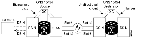
The third test is a hairpin circuit on the cross-connect card in the destination node. To perform this test, you must also create a bidirectional circuit from the source DS-N card to the source OC-N node in the transmit direction. Creating the bidirectional circuit and completing a successful hairpin eliminates the possibility that the source and destination OC-N cards, the source and destination cross-connect card, or the fiber span is responsible for the faulty circuit.
Figure 2-7 Hairpin on a destination node
Step 1
Note
Step 2
Step 3
Step 4
Step 5
Step 6
Step 7
Step 8
Step 9
Step 10
Step 11
Step 12
Step 13
Step 14
Step 15
Step 16
Step 17
Step 18
The OC-N card must be the other end of the fiber span originating from the OC-N card in Step 10. For example in a typical east-to-west slot configuration, a slot 6 OC-N card on the source node is one end of the fiber span, and the slot 12 OC-N card on the destination node is the other end. Figure 2-7 illustrates the slot to fiber span relationship.
Step 19
Step 20
Step 21
Step 22
Step 23
Step 24
Step 25
Step 26
Step 27
Step 28
Caution
Step 29
a.
b.
c.
Step 30
a.
b.
c.
Note
Step 31
a.
The test set traffic routes through the alternate cross-connect card.
b.
c.
Step 32
a.
b.
c.
d.
If the circuit is now good, the cross-connect card may have had a temporary problem that was cleared by the side switch.
Step 33
Step 34
The test set traffic routes through the alternate cross-connect card rather than the original cross-connect card.
Step 35
Step 36
Step 37
a.
b.
c.
d.
e.
Step 38
Step 39
a.
b.
c.
d.
e.
If the test traffic is not received or is poor quality and the OC-N card is a known good card, then the fiber span is suspect.
Step 40
Step 41
Step 42
Step 43
Step 44
Step 45
Step 46
Step 47
Step 48
Procedure: Perform a Facility Loopback on a Destination DS-N Card
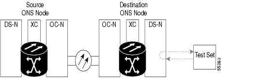
The final test is a facility loopback performed on the last card in the circuit; in this case the DS-N card in the destination node. Completing a successful facility loopback on this card eliminates the possibility that the destination node cabling, DS-N card, LIU, or EIA is responsible for a faulty circuit.
Figure 2-8 Facility loopback on a destination DS-N card
Caution
Note
Step 1
To perform a hard loop on the test set, bridge the test set transmit (Tx) and receive (Rx) terminals with an appropriate cable and send traffic across this loop to make sure the test set works properly.
Step 2
Step 3
Step 4
Note
Step 5
Step 6
Step 7
Note
Step 8
Step 9
Step 10
a.
On the Loopback subtab, select None from the Loopback Type column.
Click Apply.
b.
Step 11
Step 12
a.
b.
c.
d.
e.
Step 13
a.
b.
c.
d.
Step 14
a.
b.
c.
d.
Step 15
Step 16
Step 17
Step 18
2.2.3 Using the DS3XM-6 Card FEAC (Loopback) Functions
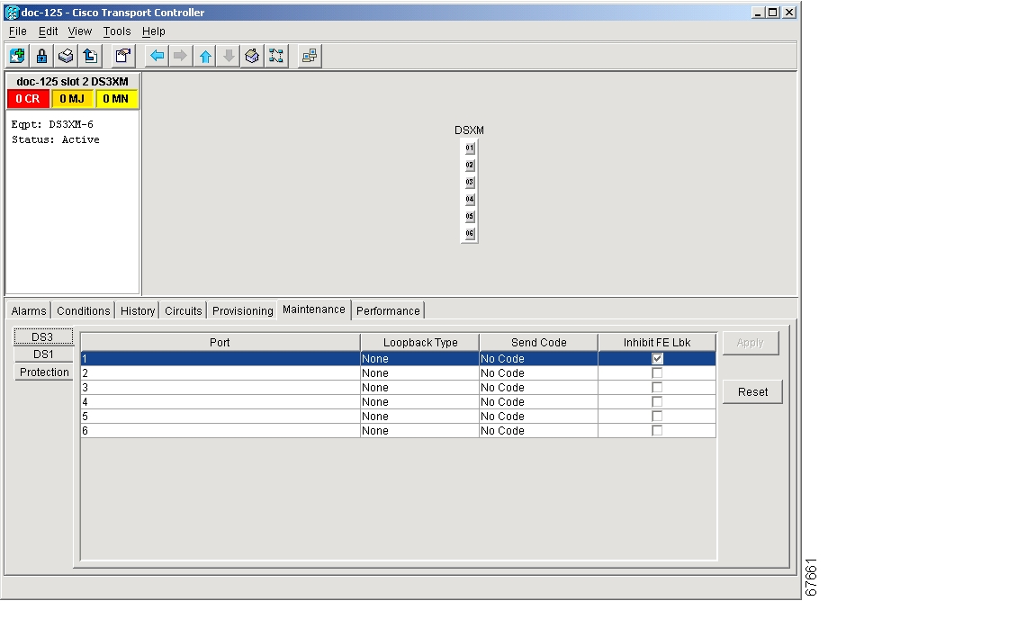
The DS3XM-6 card supports FEAC (Far End Action Code) features that are not available on basic DS-3 cards. Click the Maintenance tab at the DS3XM-6 card-level view to reveal the two additional DS3XM-6 columns. Figure 2-9 shows the DS3 subtab and the additional Send Code and Inhibit Lbk columns.
Figure 2-9 Accessing FEAC functions on the DS3XM-6 card
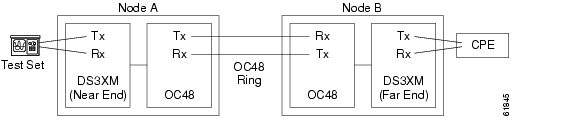
The far end in FEAC refers to the piece of equipment that is connected to the DS3XM-6 card and not the far end of a circuit. In Figure 2-10 below, if a DS3XM-6 (near-end) port is configured to send a Line Loop Code, the code will be sent to the connected test set, not the DS3XM-6 (far-end) port.
Figure 2-10 Diagram of far end action code
2.2.3.1 FEAC Send Code
The Send Code column on the maintenance tab of a DS3XM-6 port only applies to In-Service ports configured for CBIT framing. The column lets a user select No Code (the default) or Line Loop Code. Selecting Line Loop Code inserts a line loop activate FEAC (Far End Action Code) in the CBIT overhead transmitting to the connected facility. This code initiates a loopback from the facility to the ONS 15454. Selecting No Code sends a line loop deactivate FEAC code to the connected equipment, which will remove the loopback. You can also insert a FEAC for the 28 individual DS-1 circuits transmuxed into a DS-3 circuit.
2.2.3.2 FEAC Inhibit Loopback
The DS3XM-6 ports and transmuxed DS-1s initiate loopbacks when they receive FEAC Line Loop codes. If the Inhibit Loopback checkbox is checked for a DS-3 port, then that port will ignore any received FEAC Line Loop codes and will not loop back. The port can still be put into loopback manually using the Loopback Type column even if the Inhibit Loopback box is selected. Only DS-3 ports can be configured to inhibit responding to FEAC loopback commands, individual DS-1 ports cannot.
2.2.3.3 FEAC Alarms
A LPBKDS3FEAC-CMD or LPBKDS1FEAC-CMD alarm on the ONS 15454 port if a DS-3 or DS-1 FEAC loopback code has been sent to the far end.
If the ONS 15454 port is in loopback from having received a loopback activate FEAC code, a LPBKDS3FEAC or LPBKDS1FEAC alarm occurs. The alarm will clear when a loopback deactivate FEAC command is received on that port.
A DS3E card will respond to, and can inhibit, received FEAC DS3 level loopback codes. A DS3E card cannot be configured to send FEAC codes.
2.3 CTC Operation and Connectivity
This section contains troubleshooting procedures for CTC log-in or operation errors and PC and network connectivity. For a list of the procedures in this section, see Table 2-1.
2.3.1 Browser Stalls When Downloading jar File From TCC+
If the browser stalls or hangs when downloading a jar file from the TCC+ card, VirusScan software may be interfering with the operation. The problem occurs when the VirusScan Download Scan is enabled on McAfee VirusScan 4.5 or later. To correct the problem, disable the Download Scan feature.
Procedure: Disable the VirusScan Download Scan
Step 1
Step 2
Step 3
Step 4
Step 5
Step 6
Step 7
Step 8
Step 9
2.3.2 Browser Cache Points to an Invalid Directory
When the Netscape cache points to an invalid directory, CTC does not launch. Usually an error message appears before the purple login screen displays.
Procedure: Redirect the Netscape Cache to a Valid Directory
Step 1
Step 2
Step 3
Step 4
Step 5
The cache file location is usually C:\ProgramFiles\Netscape\Users\<yourname>\cache. The <yourname> segment of the file location is often the same as your e-mail username, but you can select any other valid location on the hard drive.
2.3.3 Clear the CTC Cache File
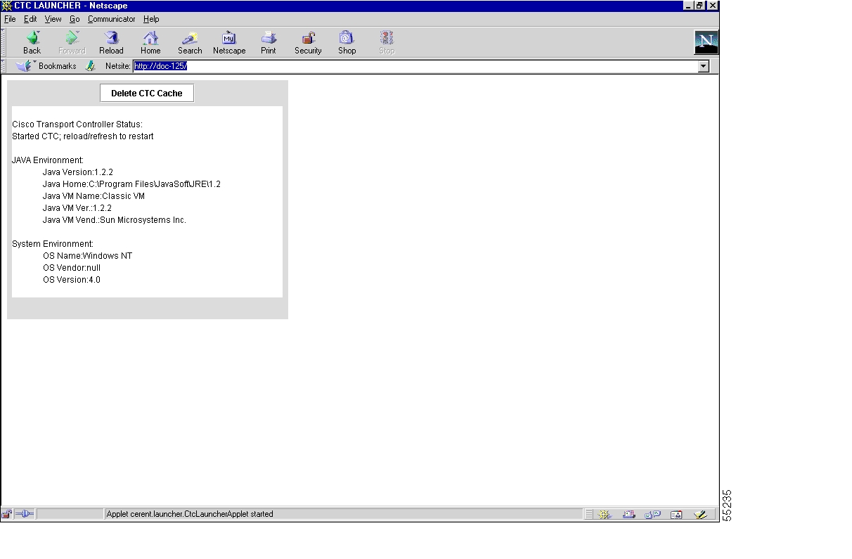
If you experience sluggish CTC operation or have problems logging into CTC, clearing the CTC cache file often helps solve these and other problems. This operation forces the ONS 15454 to download a new set of jar files to your computer hard drive.
You can delete the cache automatically with the Delete CTC Cache button or delete them manually. For CTC releases prior to 2.2, automatic deletion is unavailable.
Procedure: Delete the CTC Cache File Automatically
Step 1
Step 2
Step 3
Figure 2-11 Deleting the CTC cache
Procedure: Delete the CTC Cache File Manually
Step 1
Step 2
Step 3
Step 4
Step 5
2.3.4 Node Icon is Grey on CTC Network View
Occasionally, the CTC network view shows one or more node icons as grey in color and without a node name. This can be caused by different CTC releases not recognizing each other, the username/password on the gray nodes not matching, no IP connectivity existing between nodes, or a lost DCC connection.
2.3.5 CTC Cannot Launch Due to Applet Security Restrictions
If the error message "Unable to launch CTC due to applet security restrictions" appears after you enter the IP address in the browser window:
Step 1
Step 2
// Insert this into the system-wide or a per-user java.policy file.// DO NOT OVERWRITE THE SYSTEM-WIDE POLICY FILE--ADD THESE LINES!grant codeBase "http://*/fs/LAUNCHER.jar" {permission java.security.AllPermission;};Step 3
Step 4
CTC should now start correctly.
Step 5
2.3.6 Java Runtime Environment Incompatible
The Java° 2 Runtime Environment (JRE) contains the Java virtual machine, runtime class libraries, and Java application launcher that are necessary to run programs written in the Java programming language.
The ONS 15454 CTC is a Java application. A Java application, unlike an applet, cannot rely completely on a web browser for installation and runtime services. When you run an application written in the Java programming language, you need the correct JRE installed. The correct JRE for each CTC software release is included on the Cisco ONS 15454 software CD and on the Cisco ONS 15454 documentation CD.
If you are running multiple CTC software releases on a network, the JRE installed on the computer must be compatible with the different software releases. Table 2-2 shows JRE compatibility with ONS software releases.
2.3.7 Different CTC Releases Do Not Recognize Each Other
This situation is often accompanied by the INCOMPATIBLE-SW alarm. The software loaded on the connecting workstation and the software on the TCC+ card are incompatible. This occurs when the TCC+ software is upgraded but the PC has not yet upgraded the compatible CTC jar file. It also occurs on log-in nodes with compatible software that encounter other nodes in the network that have a newer software version.
Note
Procedure: Launch CTC to Correct the Core Version Build
Step 1
Step 2
Step 3
Step 4
Note
2.3.8 Username or Password Do Not Match
A mismatch often occurs concurrently with a NOT-AUTHENTICATED alarm. The username or password entered do not match the information stored in the TCC+. All ONS nodes must have the same username and password created to display every ONS node in the network. You can also be locked out of certain ONS nodes on a network if your username and password were not created on those specific ONS nodes.
For initial logon to the ONS 15454, type the CISCO15 user name in capital letters and click Login (no password is required). If you are using a CTC software release prior to 3.0 and CISCO15
does not work, type cerent454 for the user name.Procedure: Verify Correct Username and Password
Step 1
Step 2
Step 3
2.3.9 No IP Connectivity Exists Between Nodes
See the "Ethernet Connections" section.
2.3.10 DCC Connection Lost
See the "EOC" section on page 1-28.
2.3.11 Browser Login Does not Launch Java
If the message "Loading Java Applet" does not appear and the JRE does not launch during the initial login, you must reconfigure the PC operating system and the browser.
Step 1
Step 2
a.
b.
c.
d.
Step 3
Step 4
Step 5
Step 6
Step 7
Step 8
Step 9
Step 10
or C:\ProgramFiles\Netscape\<username>\Communicator\cache for Windows NT/2000.
Step 11
Step 12
Step 13
Step 14
Step 15
Step 16
2.3.12 Verify PC Connection to ONS 15454 (ping)
Use a standard ping command to verify the TCP/IP connection between the PC and the ONS 15454 TCC+ card. A ping command will work if the PC connects directly to the TCC+ card or uses a LAN to access the TCC+ card. If the TCP/IP connection was established and then lost, a DISCONNECTED alarm will appear on CTC.
Note
Procedure: Ping the ONS 15454
Step 1
•
•
Step 2
ping [ONS 15454 IP address]
For example, ping 192.1.0.2.
Step 3
Step 4
2.3.13 Calculate and Design IP Subnets
Cisco provides a free online tool to calculate and design IP subnets. Go to http://www.cisco.com/techtools/ip_addr.html. For information about ONS 15454 IP capability, refer to the Cisco ONS 15454 Installation and Operations Guide.
2.3.14 Ethernet Connections
You can fix most connectivity problems in an Ethernet network by following a few guidelines. See Figure 2-12 when consulting the steps in the following procedure.
Figure 2-12 Ethernet connectivity reference
Procedure: Verify Ethernet Connections
Step 1
Step 2
Step 3
Step 4
Step 5
a.
b.
c.
d.
e.
Step 6
a.
b.
c.
Step 7
Step 8
2.3.15 VLAN Cannot Connect to Network Device from Untag Port
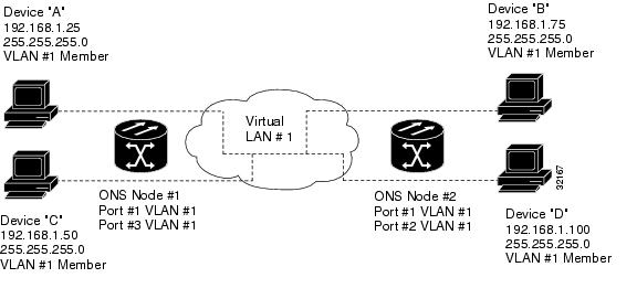
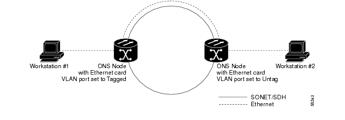
Networks that have a VLAN with one ONS 15454 Ethernet card port set to Tagged and one ONS 15454 Ethernet card set to Untag may have difficulty implementing Address Resolution Protocol (ARP) for a network device attached to the Untag port. They may also see a higher than normal runt packets count at the network device attached to the Untag port.
This implementation problem occurs because the port of the ONS 15454 Ethernet card that is set to Tagged adds the 802.1Q tag, which is four bytes long, to a 60-byte packet and sends the packet to the ONS 15454 with the Ethernet card port set to Untag. The second ONS 15454 removes the 4-byte 802.1 Q-tag and does not stuff the packet with four replacement bytes. This 64-byte packet drops in size to 60 bytes, which makes it a runt or illegal Ethernet packet. The NIC of the network device categorizes the packet as a runt and drops the packet.
Figure 2-13 A VLAN with Ethernet ports at Tagged And Untag
Dropped packets can occur when ARP attempts to match the IP address of the network device attached to the Untag port with the physical MAC address required by the network access layer. ARP uses broadcast data packets which are often 60 bytes plus an additional 4 bytes of 802.1 Q-tag information. This makes ARP especially vulnerable to the runt problem.
The solution is to set both ports in the VLAN to Tagged (detailed in the following procedure). Setting both ports in the VLAN to Tagged stops the stripping of the 4 bytes from the data packet and prevents the NIC card in the network access device from recognizing the packet as a runt and dropping it. Network devices with 802.1Q-compliant NIC cards will accept the tagged packets. Network devices with non-802.1Q compliant NIC cards will still drop these tagged packets. The solution may require upgrading network devices with non-802.1Q compliant NIC cards to 802.1Q-compliant NIC cards. You can also set both ports in the VLAN to Untag, but you will lose 802.1Q compliance.
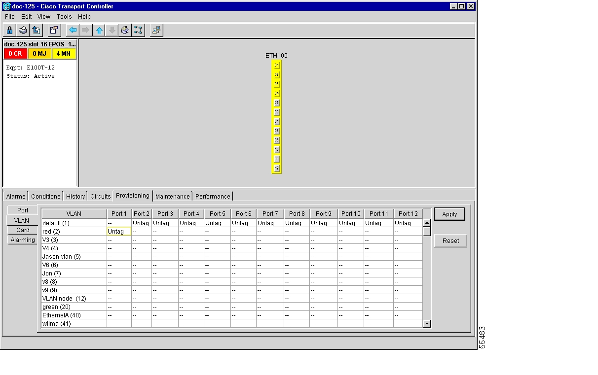
Procedure: Change VLAN Port Tag and Untagged Settings
Step 1
Step 2
Figure 2-14 Configuring VLAN membership for individual Ethernet ports
Step 3
Step 4
Note
Step 5
2.4 Circuits and Timing
This section provides solutions to circuit creation and reporting errors, as well as common timing reference errors and alarms.
2.4.1 AIS-V on DS3XM-6 Unused VT Circuits
An incomplete circuit path causes an alarm indications signal (AIS); for example, when the port on the reporting node is in-service but a node upstream on the circuit does not have an OC-N port in-service. An AIS-V indicates that an upstream failure occurred at the virtual tributary (VT) layer. AIS-V alarms also occur on DS3XM-6 VT circuits that are not carrying traffic and on stranded bandwidth.
Procedure: Clear AIS-V on DS3XM-6 Unused VT Circuits
Step 1
Step 2
Step 3
Step 4
Step 5
Step 6
Step 7
Step 8
Step 9
Step 10
Step 11
Step 12
Step 13
Step 14
Step 15
Step 16
2.4.2 Circuit Creation Error with VT1.5 Circuit
You might receive an "Error while finishing circuit creation. Unable to provision circuit. Unable to create connection object at <node name>" message when trying to create a VT1.5 circuit in CTC.
You may have run out of bandwidth on the VT cross-connect matrix at the ONS 15454 indicated in the error message. The matrix has a maximum capacity of 336 bidirectional VT1.5 cross-connects. Certain configurations will exhaust VT capacity with less than 336 bidirectional VT1.5s. Refer to the Cisco ONS 15454 Installation and Operations Guide for more information.
2.4.3 Unable to Create Circuit From DS-3 Card to DS3XM-6 Card
A circuit cannot be created from a DS-3 card to a DS3XM-6 card because the cards have different functions. DS3XM-6 converts each of its six DS-3 interfaces into 28 DS-1s for cross-connection through the network. Thus you can create a circuit from a DS3XM-6 card to a DS-1 card, but not from a DS3XM-6 card to a DS-3 card. These differences are evident in the STS path overhead. The DS-3 card uses asynchronous mapping for DS-3, which is indicated by the C2 byte in the STS path overhead that has a hex code of 04. A DS3XM-6 has a VT payload with a C2 hex value of 02.
Note
2.4.4 DS3 Card Does Not Report AIS-P From External Equipment
A DS3-12/DS3N-12/DS3-12E/DS3N-12E card does not report STS AIS-P from the external equipment/line side. The card is functioning as designed. This card terminates the port signal at the backplane so STS AIS-P is not reported from the external equipment/line side.
DS3-12/DS3N-12E cards do have DS3 header monitoring functionality, which allows you to view performance monitoring (PM) on the DS3 path. Nevertheless, you cannot view AIS-P on the STS path. For more information on the PM capabilities of the DS3-12E/DS3N-12E cards, refer to the Cisco ONS 15454 Installation and Operations Guide.
2.4.5 OC-3 and DCC Limitations
For an explanation of OC-3 and DCC limitations, see the DCC Tunnels section of the Cisco ONS 15454 Installation and Operations Guide.
2.4.6 ONS 15454 Switches Timing Reference
Timing references switch when one or more of the following problems occur:
•
•
•
•
•
•
•
The ONS 15454 internal clock operates at a Stratum 3 level of accuracy. This gives the ONS 15454 a free-running synchronization accuracy of ± 4.6 ppm and a holdover stability of less than 255 slips in the first 24 hours or 3.7x10⁻⁷/day, including temperature.
ONS 15454 free running synchronization relies on the Stratum 3 internal clock. Over an extended time period, using a higher quality Stratum 1 or Stratum 2 timing source results in fewer timing slips than a lower quality Stratum 3 timing source.
2.4.7 Holdover Synchronization Alarm
The clock is running at the frequency of the last known good reference input. This alarm is raised when the last reference input fails. See the "HLDOVERSYNC" section on page 1-43 for a detailed description of this alarm.
Note
2.4.8 Free-Running Synchronization Mode
The clock is using the internal oscillator as its only frequency reference. This occurs when no reliable, prior timing reference is available. See the "FRNGSYNC" section on page 1-42 for a detailed description of this alarm.
2.4.9 Daisy-Chained BITS Not Functioning
Daisy chaining BITS causes additional wander buildup in the network and is therefore not supported. Instead, use a timing signal generator to create multiple copies of the BITS clock and separately link them to each ONS 15454.
2.5 Fiber and Cabling
This section explains problems typically caused by cabling connectivity errors. It also includes instructions for creating Cat-5 cable and lists the optical fiber connectivity levels.
2.5.1 Bit Errors Appear for a Line Card
Bit errors on line (traffic) cards usually originate from cabling problems or low optical-line levels. The errors can be caused by synchronization problems, especially if PJ (pointer justification) errors are reported. Moving cards into different error-free slots will isolate the cause. Use a test set whenever possible because the cause of the errors could be external cabling, fiber, or external equipment connecting to the ONS 15454. Troubleshoot cabling problems using the "Network Tests" section. Troubleshoot low optical levels using the "Faulty Fiber-Optic Connections" section.
2.5.2 Faulty Fiber-Optic Connections
Faulty fiber-optic connections can be the source of SONET alarms and signal errors.
Warning
Procedure: Verify Fiber-Optic Connections
Step 1
SM or SM Fiber should be printed on the fiber span. ONS 15454 OC-N cards do not use multimode fiber.
Step 2
Step 3
a.
b.
c.
d.
Step 4
a.
b.
c.
IR cards transmit a lower output power than LR cards.
d.
e.
–
–
–
Note
Step 5
a.
b.
c.
d.
Step 6
LR cards transmit a higher output power than IR cards. When used with short runs of fiber, an LR transmitter will be too powerful for the receiver on the receiving OC-N card.
Receiver overloads occur when maximum receiver power is exceeded.
Tip
Tip
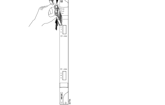
Procedure: Replace Faulty Gigabit Interface Converters
Gigabit interface converters (GBICs) are hot-swappable input/output devices that plug into a Gigabit Ethernet port to link the port with the fiber-optic network. Cisco provides two GBIC models: one for short reach applications, 15454-GBIC-SX, and one for long reach applications, 15454-GBIC-LX. The short reach, or "SX" model, connects to multimode fiber and has a maximum cabling distance of 1804 feet. The long reach, or "LX" model, requires single-mode fiber and has a maximum cabling distance of 32,810 feet.
GBICs are hot-swappable and can therefore be installed or removed while the card and shelf assembly are powered and running. GBIC transmit failure is characterized by a steadily blinking Fail LED on the Gigabit Ethernet (E1000-2/E1000-2-G) card. Figure 2-15 shows a GBIC.
Figure 2-15 A gigabit interface converter (GBIC)
Warning
Warning
Step 1
Step 2
Step 3
Note
Step 4
Step 5
Caution
Step 6
Note
Figure 2-16 Installing a GBIC on the E1000-2/E1000-2-G card
Step 7
The click indicates that the GBIC is locked into the slot.
Step 8
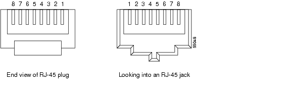
2.5.3 Create CAT-5 Cables
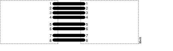
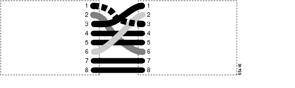
You can manufacture your own CAT-5 cables for use with the ONS 15454. Use a cross-over cable when connecting an ONS 15454 to a router, hub, LAN modem, or switch, and use a straight-through cable when connecting an ONS 15454 to a workstation. Use CAT 5 cable RJ-45 T-568B, Color Code (100 Mbps).
Figure 2-17 RJ-45 pin numbers
Figure 2-18 A straight-through cable layout
Figure 2-19 A cross-over cable layout
Note
2.5.4 Optical Card Transmit and Receive Levels
Each OC-N card has a transmit and receive connector on its faceplate.
2.6 Power and LED Tests
This section provides the "Power Supply Problems" section, the "Power Consumption for Node and Cards" section, and the "Lamp Test for Card LEDs" section.
2.6.1 Power Supply Problems
The ONS 15454 requires a constant source of DC power to properly function. Input power is -48 VDC. Power requirements range from -42 VDC to -57 VDC.
A newly installed ONS 15454 that is not properly connected to its power supply will not operate. Power problems can be confined to a specific ONS 15454 or affect several pieces of equipment on the site.
A loss of power or low voltage can result in a loss of traffic and causes the LCD clock on the ONS 15454 to default to January 1, 1970, 00:04:15. For clock reset instructions, refer to the Cisco ONS 15454 Installation and Operations Guide.
Caution
Warning
Warning
Procedure: Isolate the Cause of Power Supply Problems
Step 1
a.
b.
c.
d.
e.
f.
g.
h.
–
VDC.–
–
–
Step 2
a.
b.
c.
2.6.2 Power Consumption for Node and Cards
Refer to the "Card and Fan-Tray Assembly Power Requirements" section on page 4-5.
2.6.3 Lamp Test for Card LEDs
A lamp test verifies that all the card LEDs work. Run this diagnostic test as part of the initial ONS 15454 turn-up, a periodic maintenance routine, or any time you question whether an LED is in working order.
Procedure: Verify Card LED Operation
Step 1
Step 2
Step 3
Step 4
If a LED does not light up, the LED is faulty. Call the Cisco Technical Assistance Center (TAC) at 1-877-323-7368 and fill out an RMA to return the card.
![]()
![]()
![]()
![]()
![]()
![]()
![]()
![]()
Posted: Fri Feb 22 16:33:42 PST 2008
All contents are Copyright © 1992--2008 Cisco Systems, Inc. All rights reserved.
Important Notices and Privacy Statement.