|
|

Table Of Contents
4.1.5 Card and Fan-Tray Assembly Power Requirements
4.2 Electrical Card Protection
4.3 Electrical Card Protection and the Backplane
4.3.2 High-Density BNC Protection
4.6 Timing Communication and Control (TCC+) Card
4.6.1 TCC+ Card-Level Indicators
4.6.2 Network-Level Indicators
4.7.1 XC Card-Level Indicators
4.8.3 XCVT Card-Level Indicators
4.8.5 XCVT Card Specifications
4.9.3 XC10G Card-Level Indicators
4.9.4 XC/XCVT/XC10G Compatibility
4.9.5 XC10G Card Specifications
4.10 Alarm Interface Controller Card
4.11.2 EC1-12 Card-Level Indicators
4.11.3 EC1-12 Port-Level Indicators
4.12.2 DS1-14 Card-Level Indicators
4.12.3 DS1-14 Port-Level Indicators
4.13.2 DS1N-14 Card-Level Indicators
4.13.3 DS1N-14 Port-Level Indicators
4.14.1 DS3-12 Card-Level Indicators
4.14.2 DS3-12 Port-Level Indicators
4.15.1 DS3N-12 Card-Level Indicators
4.15.2 DS3N-12 Port-Level Indicators
4.15.3 DS3N-12 Card Specifications
4.16.1 DS3-12E Card-Level Indicators
4.16.2 DS3-12E Port-Level Indicators
4.16.4 DS3-12E Card Specifications
4.17.1 DS3N-12E Card-Level Indicators
4.17.2 DS3N-12E Port-Level Indicators
4.17.4 DS3N-12E Card Specifications
4.18.2 DS3XM-6 Card-Level Indicators
4.18.3 DS3XM-6 Port-Level Indicators
4.18.4 DS3XM-6 Card Specifications
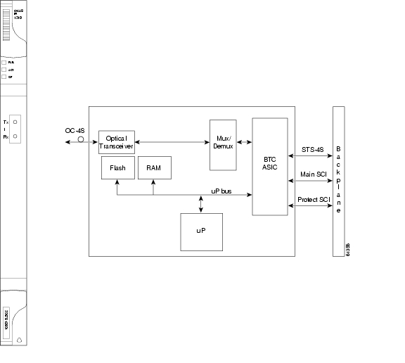
4.19 OC3 IR 4/STM1 SH 1310 Card
4.19.1 OC3 IR 4/STM1 SH 1310 Card-Level Indicators
4.19.2 OC3 IR 4/STM1 SH 1310 Port-Level Indicators
4.19.3 OC3 IR 4/STM1 SH 1310 Card Specifications
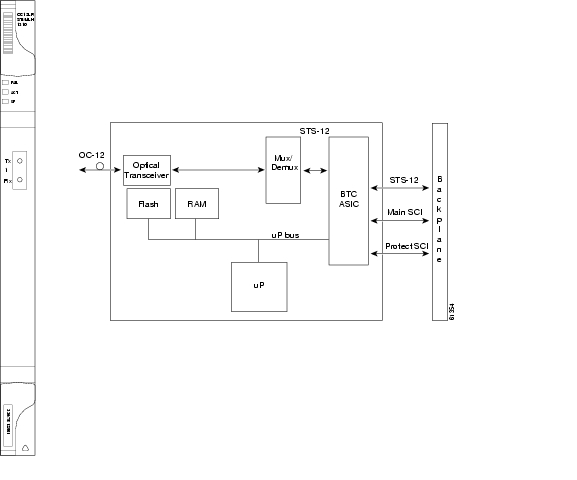
4.20 OC12 IR/STM4 SH 1310 Card
4.20.1 OC12 IR/STM4 SH 1310 Card-Level Indicators
4.20.2 OC12 IR/STM4 SH 1310 Port-Level Indicators
4.20.3 OC12 IR/STM4 SH 1310 Card Specifications
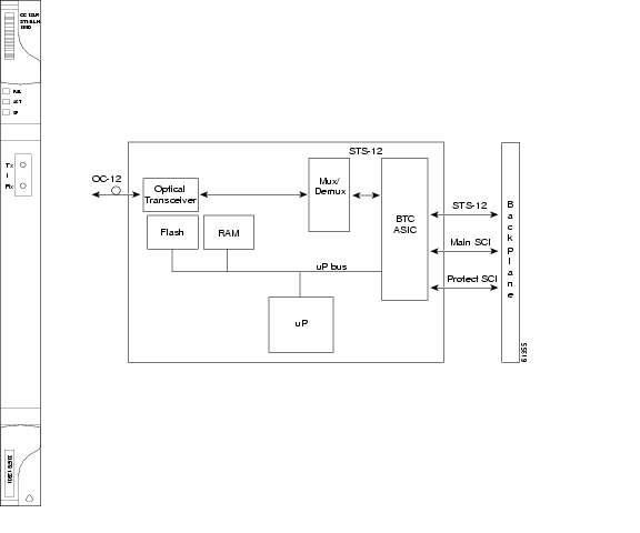
4.21 OC12 LR/STM4 LH 1310 Card
4.21.1 OC12 LR/STM4 LH 1310 Card-Level Indicators
4.21.2 OC12 LR/STM4 LH 1310 Port-Level Indicators
4.21.3 OC12 LR/STM4 LH 1310 Card Specifications
4.22 OC12 LR/STM4 LH 1550 Card
4.22.1 OC12 LR/STM4 LH 1550 Card-Level Indicators
4.22.2 OC12 LR/STM4 LH 1550 Port-Level Indicators
4.22.3 OC12 LR/STM4 LH 1550 Card Specifications
4.23.1 OC48 IR 1310 Card-Level Indicators
4.23.2 OC48 IR 1310 Port-Level Indicators
4.23.3 OC48 IR 1310 Card Specifications
4.24.1 OC48 LR 1550 Card-Level Indicators
4.24.2 OC48 LR 1550 Port-Level Indicators
4.24.3 OC48 LR 1550 Card Specifications
4.25 OC48 IR/STM16 SH AS 1310 Card
4.25.1 OC48 IR/STM16 SH AS 1310 Card-Level Indicators
4.25.2 OC48 IR/STM16 SH AS 1310 Port-Level Indicators
4.25.3 OC48 IR/STM16 SH AS 1310 Compatibility
4.25.4 OC48 IR/STM16 SH AS 1310 Card Specifications
4.26 OC48 LR/STM16 LH AS 1550 Card
4.26.1 OC48 LR/STM16 LH AS 1550 Card-Level Indicators
4.26.2 OC48 LR/STM16 LH AS 1550 Port-Level Indicators
4.26.3 OC48 LR/STM16 LH AS 1550 Compatibility
4.26.4 OC48 LR/STM16 LH AS 1550 Card Specifications
4.27 OC48 ELR/STM16 EH 100 GHz Cards
4.27.1 OC48 ELR 100 GHz Card-Level Indicators
4.27.2 OC48 ELR 100 GHz Port-Level Indicators
4.27.3 OC48 ELR 100 GHz Compatibility
4.27.4 OC48 ELR 100 GHz Card Specifications
4.28.1 OC48 ELR 200 GHz Card-Level Indicators
4.28.2 OC48 ELR 200 GHz Port-Level Indicators
4.28.3 OC48 ELR 200 GHz Compatibility
4.28.4 OC48 ELR 200 GHz Card Specifications
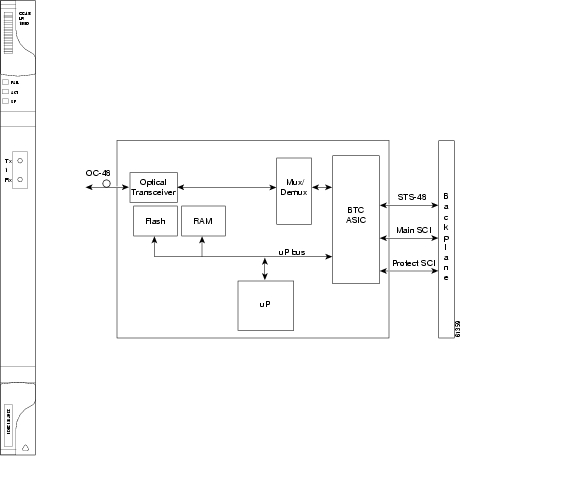
4.29 OC192 LR/STM64 LH 1550 Card
4.29.1 OC192 LR/STM64 LH 1550 Card-Level Indicators
4.29.2 OC192 LR/STM64 LH 1550 Port-Level Indicators
4.29.3 OC192 LR/STM64 LH 1550 Compatibility
4.29.4 OC192 LR/STM64 LH 1550 Card Specifications
4.30.1 E100T-G Card-Level Indicators
4.30.2 E100T-G Port-Level Indicators
4.30.4 E100T-G Card Specifications
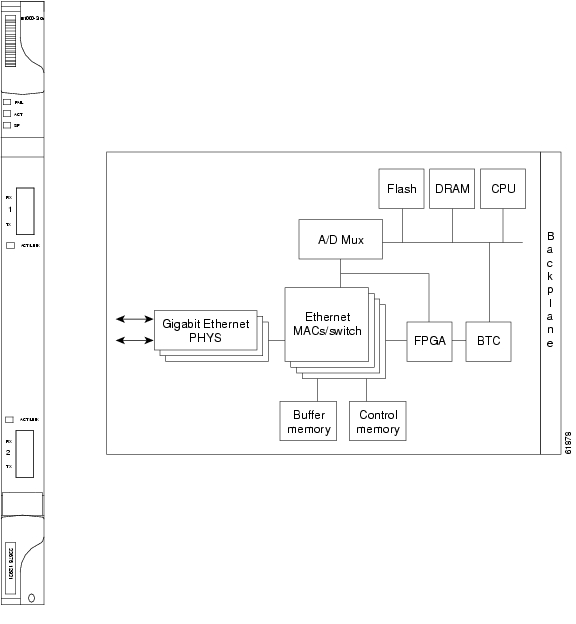
4.31.1 E1000-2-G Card-Level Indicators
4.31.2 E1000-2-G Port-Level Indicators
4.31.3 E1000-2-G Compatibility
4.31.4 E1000-2-G Card Specifications
4.32.1 E100T-12 Card-Level Indicators
4.32.2 E100T-12 Port-Level Indicators
4.32.4 E100T-12 Card Specifications
4.33.1 E1000-2 Card-Level Indicators
4.33.2 E1000-2 Port-Level Indicators
4.33.4 E1000-2 Card Specifications
Card Reference
This chapter describes Cisco ONS 15454 card features and functions. For installation and card turn-up procedures, see the Cisco ONS 15454 Installation and Operations Guide.
4.1 Card Overview
The card overview section summarizes card functions, power consumption, temperature ranges, and compatibility.
Note
Each card is marked with a symbol that corresponds to a slot (or slots) on the ONS 15454 shelf assembly. The cards are then installed into slots displaying the same symbols. See the Cisco ONS 15454 Installation and Operations Guide for a list of slots and symbols.
4.1.1 Common Control Cards
Table 4-1 lists five common control cards for the Cisco ONS 15454 and summarizes card functions.
Table 4-1 Common Control Card Functions
The TCC+ is the main processing center for the ONS 15454 and provides system initialization, provisioning, alarm reporting, maintenance, and diagnostics.
See the "Timing Communication and Control (TCC+) Card" section
The XC card is the central element for switching; it establishes connections and performs time division switching (TDS).
See the "XC Cross-Connect Card" section
The XCVT card is the central element for switching; it establishes connections and performs time division switching (TDS). The XCVT can manage STS and VT circuits up to 48c.
The XC10G card is the central element for switching; it establishes connections and performs time division switching (TDS). The XC10G can manage STS and VT circuits up to 192c. The XC10G allows up to four times the bandwidth of current XC and XCVT cards.
The AIC card provides customer-defined alarms with its additional input/output alarm contact closures.
4.1.2 Electrical Cards
Table 4-2 lists the Cisco ONS 15454 electrical cards.
Table 4-2 Electrical Cards for the ONS 15454
The EC1-12 card provides 12 STS-1 electrical ports.
See the "EC1-12 Card" section
The DS1-14 card provides 14 DS-1 ports.
See the "DS1-14 Card" section
The DS1N-14 card provides 14 DS-1 ports but can also provide 1:N protection when necessary.
See the "DS1N-14 Card" section
The DS3-12 card has 12 DS-3 ports.
See the "DS3-12 Card" section
The DS3N-12 card has 12 DS-3 ports but can also provide 1:N protection when necessary.
See the "DS3N-12 Card" section
The DS3-12E card has 12 ports, supports 1:1 protection, and provides enhanced performance-monitoring functions.
See the "DS3-12E Card" section
The DS3N-12E card has 12 ports, supports 1:N protection, and provides enhanced performance-monitoring functions.
See the "DS3N-12E Card" section
The DS3XM-6 card can convert six framed DS-3 network connections into 168 VT1.5s.
See the "DS3XM-6 Card" section
4.1.3 Optical Cards
Table 4-3 lists the Cisco ONS 15454 optical cards.
Table 4-3 Optical Cards for the ONS 15454
The OC3 IR 4 1310 card provides four intermediate or short-range OC-3 ports.
Note
The OC12 IR 1310 card provides one intermediate or short-range OC-12 port.
Note
The OC12 LR 1310 card provides one long-range OC-12 port and operates at 1310 nm.
Note
The OC12 LR 1550 card provides one long-range OC-12 port and operates at 1550 nm.
Note
The OC3 IR 4/STM1 SH 1310 card provides four intermediate or short-range OC-3 ports.
The OC12 IR/STM4 SH 1310 card provides one intermediate or short-range OC-12 port.
The OC12 LR/STM4 LH 1310 card provides one long-range OC-12 port and operates at 1310 nm.
The OC12 LR/STM4 LH 1550 card provides one long-range OC-12 port and operates at 1550 nm.
The OC48 IR 1310 card provides one intermediate-range OC-48 port and operates at 1310 nm. This card functions in slots 5, 6, 12, or 13 only.
See the "OC48 IR 1310 Card" section
The OC48 LR 1550 card provides one long-range OC-48 port and operates at 1550 nm. This card functions in slots 5, 6, 12, or 13 only.
See the "OC48 LR 1550 Card" section
The OC48 IR/STM16 SH AS 1310 card provides one intermediate-range OC-48 port and operates in any multispeed or high-speed card slot.
The OC48 LR/STM16 LH AS 1550 card provides one long-range OC-48 port and operates in any multispeed or high-speed card slot.
Thirty-seven distinct OC48 ITU 100 GHz dense wavelength division multiplexing (DWDM) cards provide the ONS 15454 DWDM channel plan.
Eighteen distinct OC48 ITU 200GHz DWDM cards provide the ONS 15454 DWDM channel plan.
See the "OC48 ELR 200 GHz Cards" section
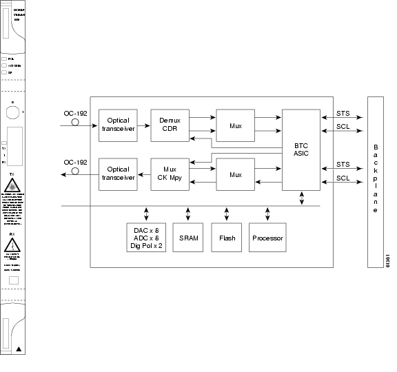
The OC192 LR/STM64 LH 1550 card provides one long-range OC-192 port and operates at 1550 nm.
4.1.4 Ethernet Cards
Table 4-4 lists the Cisco ONS 15454 Ethernet cards.
.
Table 4-4 Ethernet Cards for the ONS 15454
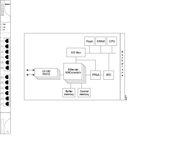
The E100T-12 card provides 12 switched, autosensing, 10/100 Base-T Ethernet ports.
See the "E100T-12 Card" section
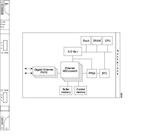
The E1000-2 card provides two ports of IEEE-compliant, 1000 Mbps ports.
See the "E1000-2 Card" section
The E100T-G card provides 12 switched, autosensing, 10/100 Base-T Ethernet ports and is compatible with the XC10G card.
See the "E100T-G Card" section
The E1000-2-G card provides two ports of IEEE-compliant, 1000 Mbps ports and is compatible with the XC10G card.
See the "E1000-2-G Card" section
4.1.5 Card and Fan-Tray Assembly Power Requirements
Table 4-5 lists power requirements for individual cards and Table 4-6 shows fan-tray assembly power requirements.
Note
Table 4-6 Fan Tray Assemblies
58
1.21
198
95
1.98
324
4.1.6 Card Temperature Ranges
Table 4-7 shows C-Temp and I-Temp compliant cards and their product names.
Note
is displayed on the faceplate of an I-Temp compliant card. A card without this symbol is C-Temp compliant.
4.1.7 Card Compatibility
The tables below list ONS 15454 cards, compatible software versions, and compatible cross-connect cards. Read each card description for detailed information about the card. In the tables below, Yes means cards are compatible with the listed software versions and cross-connect cards. Table cells with dashes mean cards are not compatible with the listed software versions or cross-connect cards.
4.2 Electrical Card Protection
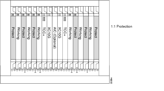
The ONS 15454 provides a variety of electrical card protection methods. This section describes the protection options. Figure 4-1 shows a 1:1 protection scheme and Figure 4-2 shows a 1:N protection scheme.
4.2.1 Protection, 1:1
In 1:1 protection, a working card is paired with a protect card of the same type. If the working card fails, the traffic from the working card switches to the protect card. When the failure on the working card is resolved, traffic automatically reverts to the working card. Figure 4-1 shows the ONS 15454 in a 1:1 protection configuration. Each working card in an odd-numbered slot is paired with a protect card in an even-numbered slot: Slot 1 is protecting Slot 2, Slot 3 is protecting Slot 4, Slot 5 is protecting Slot 6, Slot 17 is protecting Slot 16, Slot 15 is protecting Slot 14, and Slot 13 is protecting Slot 12. The following electrical cards use a 1:1 protection scheme: EC1-12, DS1-14, DS3-12 and DS3-12E.
Figure 4-1 ONS 15454 cards in a 1:1 protection configuration
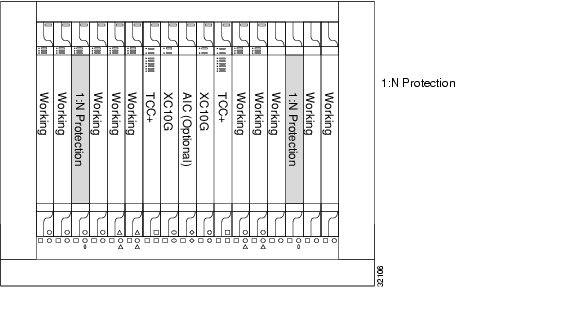
4.2.2 Protection, 1:N
1:N protection allows a single card to protect up to five working cards of the same DS-N level. A DS1N-14 card protects DS1-14 cards, a DS3N-12 card protects DS3-12 cards, and DS3N-12E cards protect DS3-12E cards. The standard DS1-14, DS3-12, and DS3-12E cards provide 1:1 protection only. Currently, 1:N protection operates only at the DS-1 and DS-3 levels. 1:N cards have added circuitry to act as the protection card in a 1:N protection group. Otherwise, the card is identical to the standard card and can serve as a normal working card.
The physical DS-1 or DS-3 interfaces on the ONS 15454 backplane use the working card until the working card fails. When the node detects this failure, the protection card takes over the physical DS-1 or DS-3 electrical interfaces through the relays and signal bridging on the backplane. Figure 4-2 shows the ONS 15454 in a 1:N protection configuration. Each side of the shelf assembly has only one card protecting all of the cards on that side.
Figure 4-2 ONS 15454 cards in a 1:N protection configuration
4.2.2.1 Revertive Switching
1:N protection supports revertive switching. Revertive switching sends the electrical interfaces (traffic) back to the original working card after the card comes back online. Detecting an active working card triggers the reversion process. There is a variable time period for the lag between detection and reversion, called the revertive delay, which you can set using the ONS 15454 software, Cisco Transport Controller (CTC). To set the revertive delay, see the Cisco ONS 15454 Installation and Operations Guide. All cards in a protection group share the same reversion settings. 1:N protection groups default to automatic reversion.
4.2.2.2 Protection Guidelines, 1:N
Several rules apply to 1:N protection groups in the ONS 15454:
•
•
•
The ONS 15454 supports 1:N equipment protection for all add-drop multiplexer configurations (ring, linear, and terminal), as specified by Telcordia GR-253-CORE.
The ONS 15454 automatically detects and identifies a 1:N protection card when the card is installed in Slot 3 or Slot 15. However, the slot containing the 1:N card in a protection group must be manually provisioned as a protect slot because by default all cards are working cards.
For detailed procedures on setting up DS-1 and DS-3 protection groups, see the protection information in the Cisco ONS 15454 Installation and Operations Guide.
4.3 Electrical Card Protection and the Backplane
Protection schemes for electrical cards differ slightly depending on the Electrical Interface Assembly (EIA) type used on the ONS 15454 backplane. The difference is due to the varying connector size. For example, because BNC connectors are larger, fewer DS3-12 cards can be supported when using a BNC connector.
Note
Caution
4.3.1 Standard BNC Protection
When you use BNC connectors, the ONS 15454 supports 1:1 protection or 1:N protection for a total of four working DS-3 electrical cards. If you are using EC-1 electrical cards with the BNC EIA, the ONS 15454 supports 1:1 protection and a total of four working cards. Slots 2, 4, 14 and 16 are designated working slots. These slots are mapped to a set of 12 BNC connectors on the EIA. These slots can be used without protection for unprotected DS-3 access.
With 1:N or 1:1 protection, Slots 1, 3, 15 and 17 are designated for protection when BNC connectors are used. With 1:N protection, Slots 3 and 15 are also designated for protection when BNC connectors are used. Slots 5, 6, 12, and 13 do not support DS3-12 cards when you use the regular BNC EIA.
4.3.2 High-Density BNC Protection
When you use the High-Density BNC EIA, the ONS 15454 supports 1:1 protection or 1:N protection for eight total working DS-3 electrical cards. If you are using EC-1 electrical cards with the High-Density BNC EIA, the ONS 15454 supports 1:1 protection and a total of eight working cards. Slots 1, 2, 4, 5, 13, 14, 16, and 17 are designated working slots.
These slots are mapped to a set of 12 BNC type connectors on the EIA. You can use these slots without protection for unprotected DS-3 or EC-1 access. Slots 3 and 15 are designated for 1:N protection slots when you use BNC connectors with the High-Density BNC EIA. Slots 6 and 12 do not support DS-3 or EC-1 cards when you use the High-Density BNC EIA.
4.3.3 SMB Protection
When you use SMB connectors, the ONS 15454 supports 1:1 or 1:N protection for the DS-1 and the DS-3 electrical cards. If you are using EC-1 cards with the SMB EIA, the ONS 15454 supports 1:1 protection. Working and protection electrical cards are defined by card slot pairs (the same card type is used for working and protect modules; the protection of the card is defined by the slot where it is housed). Each slot maps to a set of 12 or 14 SMB connectors on the EIA depending on the number of ports on the corresponding card. Any slot can be used without protection for unprotected DS-1, DS-3, or EC-1 access.
The DS1N-14 card can be a working or protect card in 1:1 or 1:N protection schemes. When used with 1:N protection, the DS1N-14 card can protect up to five DS1-14 plug-ins using the SMB connectors with the DS-1 electrical interface adapters (baluns).
4.3.4 AMP Champ Protection
When you use AMP Champ connectors, the ONS 15454 supports 1:1 or 1:N protection for the DS-1 cards. The DS1N-14 card can be a working or protect card in 1:1 or 1:N protection schemes. When used with 1:N protection, the DS1N-14 card can protect up to five DS1-14 plug-ins using the AMP Champ EIA.
4.4 Optical Card Protection
With 1+1 port-to-port protection, any number of ports on the protect card can be assigned to protect the corresponding ports on the working card. The working and protect cards do not have to be placed side by side in the node. A working card must be paired with a protect card of the same type, for example, an OC-3 card should be paired with another OC-3 card. The protection takes place on the port level, any number of ports on the protect card can be assigned to protect the corresponding ports on the working card.
For example, on a four-port card, you can assign one port as a protection port on the protect card (protecting the corresponding port on the working card) and leave three ports unprotected. Conversely, you can assign three ports as protection ports and leave one port unprotected.
Note
With 1:1 or 1:N protection (electrical cards), the protect card must protect an entire slot. In other words, all the ports on the protect card will be used in the protection scheme.
1+1 span protection can be either revertive or non-revertive. With non-revertive 1+1 protection, when a failure occurs and the signal switches from the working card to the protect card, the signal stays switched to the protect card until it is manually switched back. Revertive 1+1 protection automatically switches the signal back to the working card when the working card comes back online.
You create and modify protection schemes using CTC software. For more information, see the Cisco ONS 15454 Installation and Operations Guide.
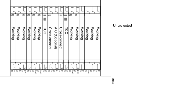
4.5 Unprotected Cards
Unprotected cards are not included in a protection scheme; therefore, a card failure or a signal error results in lost data. Because no bandwidth lies in reserve for protection, unprotected schemes maximize the available ONS 15454 bandwidth. Figure 4-3 shows the ONS 15454 in an unprotected configuration. All cards are in a working state.
Figure 4-3 ONS 15454 in an unprotected configuration
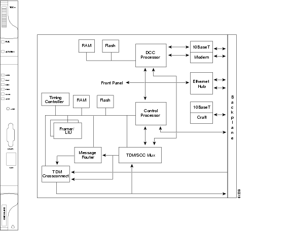
4.6 Timing Communication and Control (TCC+) Card
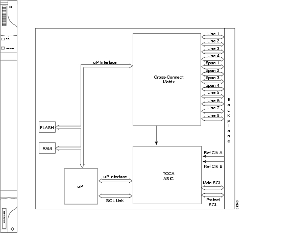
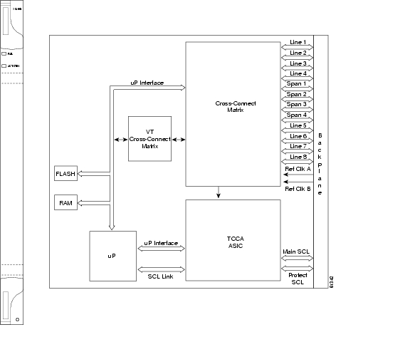
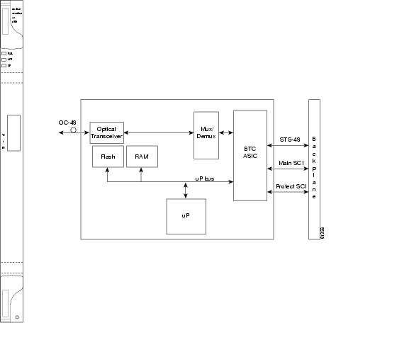
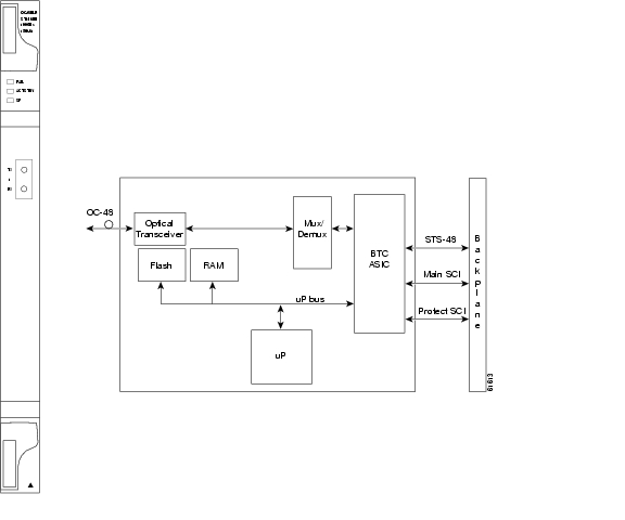
The TCC+ performs system initialization, provisioning, alarm reporting, maintenance, diagnostics, IP address detection/resolution, SONET Data Communications Channel (DCC) termination, and system fault detection for the ONS 15454. The TCC+ also ensures that the system maintains Telcordia timing requirements. Figure 4-4 shows the TCC+ faceplate and a block diagram of the card.
Figure 4-4 TCC+ faceplate and block diagram
The node database, IP address, and system software are stored in TCC+ non-volatile memory, which allows quick recovery in the event of a power or card failure.
The TCC+ supports multichannel, high-level data link control (HDLC) processing for the DCC. Up to 48 DCCs can be routed over the Serial Communication Interface (SCI) and terminated at the TCC+. The TCC+ selects and processes ten DCCs to facilitate remote system management interfaces.
The TCC+ performs all system-timing functions for each ONS 15454. The TCC+ monitors the recovered clocks from each traffic card and two DS-1 (BITS) interfaces for frequency accuracy. The TCC+ selects a recovered clock, a BITS, or an internal Stratum 3 reference as the system-timing reference. You can provision any of the clock inputs as primary or secondary timing sources. A slow-reference tracking loop allows the TCC+ to synchronize with the recovered clock, which provides holdover if the reference is lost.
Install TCC+ cards in Slots 7 and 11 for redundancy. If the active TCC+ fails, traffic switches to the protect TCC+. All TCC+ protection switches conform to protection switching standards of less than 50 ms.
The TCC+ features an RJ-45 10Base-T LAN port and an RS-232 DB9 type craft interface for user interfaces. The TL1 craft port runs at 9600 bps.
Caution
4.6.1 TCC+ Card-Level Indicators
The TCC+ faceplate has eight LEDs. The first two LEDs are card-level indicators.
4.6.2 Network-Level Indicators
The TCC+ faceplate has eight LEDs. Six LEDs are network-level indicators.
.
4.6.3 TCC+ Specifications
•
–
–
•
–
–
•
–
–
–
–
•
–
C-Temp (15454-TCC+): 0 to +55 degrees Celsius
I-Temp (15454-TCC+T): -40 to +65 degrees Celsius
Note
is displayed on the faceplate of an I-Temp compliant card. A card without this symbol is C-Temp compliant.
–
–
•
–
–
•
–
4.7 XC Cross-Connect Card
The cross-connect card is the central element for ONS 15454 switching. Available cross-connects are the XC, XCVT, and XC10G. The XC establishes connections and performs time division switching (TDS) at the STS-1 level between ONS 15454 traffic cards. The XC card faceplate and block diagram are shown in Figure 4-5. The cross-connect matrix is shown in Figure 4-6.
Figure 4-5 XC card faceplate and block diagram
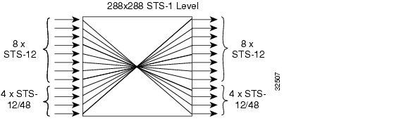
The switch matrix on the XC card consists of 288 bidirectional ports. When creating bidirectional STS-1 cross-connects, each cross-connect uses two STS-1 ports. This results in 144 bidirectional STS-1 cross-connects. The switch matrix is fully crosspoint, non-blocking, and broadcast supporting. (Any STS-1 on any port can be connected to any other port, meaning that the STS cross-connections are non blocking.) This allows network operators to concentrate or groom low-speed traffic from line cards onto high-speed transport spans and to drop low-speed traffic from transport spans onto line cards.
Figure 4-6 XC cross-connect matrix
The XC card has 12 input ports and 12 output ports. Four input and output ports operate at either STS-12 or STS-48 rates. The remaining eight input and output ports operate at the STS-12 rate. An STS-1 on any of the input ports can be mapped to an STS-1 output port, thus providing full STS-1 time slot assignments (TSA).
The XC card works with the TCC+ card to maintain connections and set up cross-connects within the ONS 15454. Either the XC, XCVT, or XC10G is required to operate the ONS 15454. You establish cross-connect and provisioning information through CTC. The TCC+ establishes the proper internal cross-connect information and relays the setup information to the cross-connect card.
Caution
For simplex operation, you can install a single XC card in Slots 8 or 10. A second XC should be added for redundancy. The card has no external interfaces. All cross-connect card interfaces are provided through the ONS 15454 backplane.
4.7.1 XC Card-Level Indicators
The XC card faceplate has two card-level LEDs.
4.7.2 XC Specifications
•
–
–
•
–
C-Temp (15454-XC): 0 to +55 degrees Celsius
I-Temp (15454-XC-T): -40 to +65 degrees Celsius
Note
The I-Temp symbol is displayed on the faceplate of an I-Temp compliant card. A card without this symbol is C-Temp compliant.
–
–
•
–
–
–
–
•
–
4.8 XCVT Cross-Connect Card
The XCVT card provides the same STS capability as a standard XC card and also provides VT cross-connection. The XCVT provides non-blocking STS-48 capacity to all of the high-speed slots and non-bidirectional blocking STS-12 capacity to all multispeed slots. Any STS-1 on any port can be connected to any other port, meaning that the STS cross-connections are non blocking.
Figure 4-7 shows the XCVT faceplate and block diagram. Figure 4-8 shows the cross-connect matrix.
Figure 4-7 XCVT faceplate and block diagram
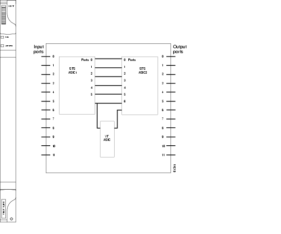
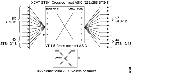
The STS-1 switch matrix on the XCVT card consists of 288 bidirectional ports and adds a VT matrix that can manage up to 336 bidirectional VT1.5 ports or the equivalent of a bidirectional STS-12. The VT1.5-level signals can be cross connected, dropped, or rearranged. The TCC+ assigns bandwidth to each slot on a per STS-1 or per VT1.5 basis. The switch matrices are fully crosspoint and broadcast supporting.
The XCVT card works with the TCC+ card to maintain connections and set up cross-connects within the node. Either the XCVT, XC10G, or XC is required to operate the ONS 15454. You can establish cross-connect (circuit) information through CTC. The TCC+ establishes the proper internal cross-connect information and relays the setup information to the XCVT card.
Caution
Figure 4-8 XCVT cross-connect matrix
4.8.1 VT Mapping
The VT structure is designed to transport and switch payloads below the DS-3 rate. The Cisco ONS 15454 performs Virtual Tributary (VT) mapping according to Telcordia GR-253 standards. Table 4-17 shows the VT numbering scheme for the ONS 15454 as it relates to the Telcordia standard.
4.8.2 XCVT Hosting DS3XM-6
The XCVT card works with DS3XM-6 (transmux) cards. A single DS3XM-6 can demultiplex (map down to a lower rate) six DS-3 signals into 168 VT1.5s that the XCVT card manages and cross connects. XCVT cards host a maximum of 336 bidirectional VT1.5s. In most network configurations, two DS3XM-6 cards are paired as working and protect cards.
4.8.3 XCVT Card-Level Indicators
The XCVT faceplate has two card-level LEDs.
4.8.4 XC/XCVT Compatibility
The XCVT card is compatible with the XC cards. The XCVT supports run-time compatibility with the XC cross-connect both within a single node and within a ring of mixed XCVT and XC nodes. However, working and protect cards within a single ONS 15454 must be either two XC cards or two XCVT cards. If an XC card or an XCVT card are used together as a working and protect pair, the XCVT acts as an XC card.
The XC and XCVT are supported in unidirectional path switched ring (UPSR) and bidirectional line switched ring (BLSR) configurations. VT and STS-level cross-connect and protection management are also supported in either type of ring. Nodes that rearrange or drop VTs must use an XCVT. Nodes that only rearrange or drop STSs can use an XC. You do not need to upgrade STS-only nodes to XCVT in a ring that can handle both VT and STS drop/rearrangement. In this scenario, however, the XC must run Software R2.0 or higher.
When upgrading from XC to XCVT cards, the first XCVT card installed acts as an XC card until the second XCVT card is installed. For more information, see Chapter 3, "Maintenance."
To create an STS-capable ring that allows VT drops at some nodes, all of the nodes in the ring must first run Software R2.0 or higher. The nodes that allow VT drops must use XCVT, but the nodes that do not allow VT drops can use the XC or XCVT card.
4.8.5 XCVT Card Specifications
•
–
C-Temp (15454-XC-VT): 0 to +55 degrees Celsius
I-Temp (15454-XC-VT-T): -40 to +65 degrees Celsius
Note
The I-Temp symbol is displayed on the faceplate of an I-Temp compliant card. A card without this symbol is C-Temp compliant.
–
–
•
–
–
–
–
•
–
4.9 XC10G Cross-Connect Card
New to Software R3.1 is the XC10G card ( Figure 4-9), which cross-connects STS-12, STS-48, and STS-192 signal rates. The XC10G allows up to four times the bandwidth of current XC and XCVT cards. The XC10G provides a maximum of 1152 STS-1 cross-connections. Any STS-1 on any port can be connected to any other port, meaning that the STS cross-connections are non blocking.
Figure 4-9 shows the XC10G faceplate and block diagram. Figure 4-10 shows the cross-connect matrix.
Figure 4-9 XC10G faceplate and block diagram
The XC10G card manages up to 336 bidirectional VT1.5 ports and 576 bidirectional STS-1 ports. The TCC+ assigns bandwidth to each slot on a per STS-1 or per VT1.5 basis.
Either the XC10G, XCVT, or XC is required to operate the ONS 15454. You can establish cross-connect (circuit) information through the Cisco Transport Controller (CTC). The TCC+ establishes the proper internal cross-connect information and sends the setup information to the cross-connect card.
Caution
Figure 4-10 XC10G cross-connect matrix
4.9.1 VT Mapping
The VT structure is designed to transport and switch payloads below the DS-3 rate. The Cisco ONS 15454 performs Virtual Tributary (VT) mapping according to Telcordia GR-253 standards. Table 4-19 shows the VT numbering scheme for the ONS 15454 as it relates to the Telcordia standard.
4.9.2 XC10G Hosting DS3XM-6
The XC10G card works with the DS3XM-6 (transmux) card. A single DS3XM-6 can demultiplex (map down to a lower rate) six DS-3 signals into 168 VT1.5s that the XC10G card manages and cross connects. XC10G cards host a maximum of 336 bidirectional VT1.5 ports. In most network configurations, two DS3XM-6 cards are paired as working and protect cards.
4.9.3 XC10G Card-Level Indicators
The XC10G faceplate has two card-level LEDs.
4.9.4 XC/XCVT/XC10G Compatibility
The XC10G supports the same features as the XC and XCVT cross-connects. The XC10G card is required for OC-192 and OC-48 any-slot operation. Do not use the XCVT or XC cards if you are using the OC-192 card, or if you placed one of the OC-48 any slot cards in a multispeed slot.
Note
The TCC+ card, Software R3.1 or higher and the new 15454-SA-ANSI shelf assembly are required for the operation of the XC10G. If you are using Ethernet cards, the E1000-2-G or the E100T-G must be used when the XC10G cross-connect card is in use. Do not pair an XC or XCVT with an XC10G. When upgrading from XC or XCVT to the XC10G card, see the Cisco ONS 15454 Installation and Operations Guide for more information.
4.9.5 XC10G Card Specifications
•
–
C-Temp (15454-XC-10G): 0 to +55 degrees Celsius
–
–
•
–
–
–
–
•
–
4.10 Alarm Interface Controller Card
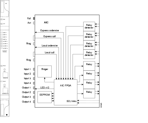
The optional Alarm Interface Controller (AIC) card provides customer-defined alarm input/output (I/O) and supports local and express orderwire. Figure 4-11 shows the AIC faceplate and a block diagram of the card. Figure 4-12 shows the RJ-11 cable.
Figure 4-11 AIC faceplate and block diagram
4.10.1 User-Defined Alarms
The AIC card provides input/output alarm contact closures. You can define up to four external alarms and four external controls. The physical connections are made using the backplane wire-wrap pins. The alarms are defined using CTC and TL1. For instructions, see the Cisco ONS 15454 Installation and Operations Guide.
Each alarm contact has a corresponding LED on the front panel of the AIC that indicates that the status of the alarm. External alarms (input contacts) are typically used for external sensors such as open doors, temperature sensors, flood sensors, and other environmental conditions. External controls (output contacts) are typically used to drive visual or audible devices such as bells and lights, but they can control other devices such as generators, heaters, and fans.
You can program each of the four input alarm contacts separately. Choices include Alarm on Closure or Alarm on Open, an alarm severity of any level (Critical, Major, Minor, Not Alarmed, Not Reported), a Service Affecting or Non-Service Affecting alarm-service level, and a 63-character alarm description for CTC display in the alarm log. You cannot assign the fan-tray abbreviation for the alarm; the abbreviation reflects the generic name of the input contacts. The alarm condition remains raised until the external input stops driving the contact or you provision the alarm input.
The output contacts can be provisioned to close on a trigger or to close manually. The trigger can be a local alarm severity threshold, a remote alarm severity, or a virtual wire:
•
•
•
You can also program the output alarm contacts (external controls) separately. In addition to provisionable triggers, you can manually force each external output contact to open or close. Manual operation takes precedence over any provisioned triggers that might be present.
4.10.2 Orderwire
Orderwire allows a craftsperson to plug a phoneset into an ONS 15454 and communicate with craftspeople working at other ONS 15454s or other facility equipment. The orderwire is a pulse code modulation (PCM) encoded voice channel that uses E1 or E2 bytes in section/line overhead.
The AIC allows simultaneous use of both local (section overhead signal) and express (line overhead channel) orderwire channels on a SONET ring or particular optics facility. Local orderwire also allows communication at regeneration sites when the regenerator is not a Cisco device.
You can provision orderwire functions with CTC similar to the current provisioning model for DCC channels. In CTC you provision the orderwire communications network during ring turn-up so that all NEs on the ring can reach one another. Orderwire terminations (i.e. the optics facilities that receive and process the orderwire channels) are provisionable. Both express and local orderwire can be configured as on or off on a particular SONET facility. The ONS 15454 supports up to four orderwire channel terminations per shelf. This allows linear, single ring, dual ring, and small hub-and-spoke configurations. Keep in mind that orderwire is not protected in ring topologies such as BLSR and UPSR.
Caution
The ONS 15454 implementation of both local and express orderwire is broadcast in nature. The line acts as a party line. There is no signalling for private point-to-point connections. Anyone who picks up the orderwire channel can communicate with all other participants on the connected orderwire subnetwork. The local orderwire party line is separate from the express orderwire party line. Up to four OC-N facilities for each local and express orderwire are provisionable as orderwire paths.
The AIC supports a "call" button on the module front panel which, when pressed, causes all ONS 15454 AICs on the orderwire subnetwork to "ring." The ringer/buzzer resides on the AIC. There is also a "ring" LED that mimics the AIC ringer. It flashes when any "call" button is pressed on the orderwire subnetwork. The "call" button and ringer/LED allow a remote craftsperson to get the attention of craftspeople across the network.
The orderwire ports are standard RJ-11 receptacles. The pins on the orderwire ports correspond to the tip and ring orderwire assignments.
Table 4-21 Orderwire Pin Assignments
1
Four-wire receive ring
2
Four-wire transmit tip
3
Two-wire ring
4
Two-wire tip
5
Four-wire transmit ring
6
Four-wire receive tip
When provisioning the orderwire subnetwork, make sure that an orderwire loop does not exist. Loops cause oscillation and an unusable orderwire channel.
Figure 4-12 RJ-11 cable
4.10.3 AIC Specifications
•
–
C-Temp (15454-AIC): 0 to +55 degrees Celsius
I-Temp (15454-AIC-T): -40 to +65 degrees Celsius
Note
The I-Temp symbol is displayed on the faceplate of an I-Temp compliant card. A card without this symbol is C-Temp compliant.
–
–
•
–
–
•
–
4.11 EC1-12 Card
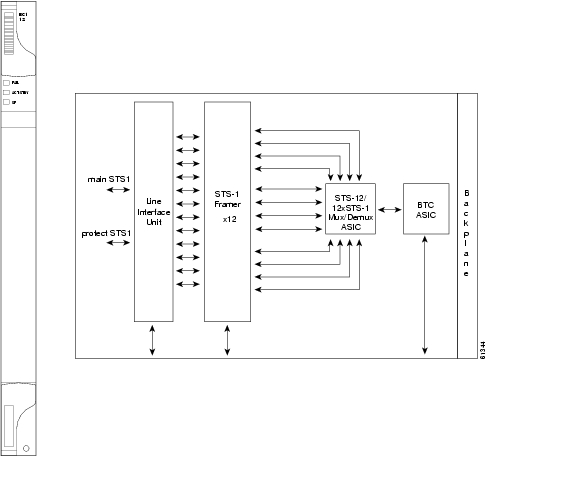
The EC1-12 card provides 12 Telcordia-compliant, GR-253 STS-1 electrical ports per card. Each port operates at 51.840 Mbps over a single 75 ohm 728A or equivalent coaxial span. Figure 4-13 shows the EC1-12 faceplate and a block diagram of the card.
Figure 4-13 EC1-12 faceplate and block diagram
STS path selection for UNEQ-P, AIS-P, and bit error rate (BER) thresholds is done on the SONET ring interfaces (optical cards) in conjunction with the STS cross-connect. The EC1-12 terminates but does not select the 12 working STS-1 signals from the backplane. The EC1-12 maps each of the 12 received EC1 signals into 12 STS-1s with visibility into the SONET path overhead.
You can install the EC1-12 card in any multispeed or high-speed card slot on the ONS 15454. Each EC1-12 interface features DSX-level (digital signal cross-connect frame) outputs supporting distances up to 450 feet depending on facility conditions.
An EC1-12 card can be 1:1 protected with another EC1-12 card but cannot protect more than one EC1-12 card. You must install the EC1-12 in an even-numbered slot to serve as a working card and in an odd-numbered slot to serve as a protect card.
4.11.1 EC1-12 Hosted by XCVT
All 14 VT1.5 payloads from a EC1-12 card are carried in a single STS-1 to the XC or XCVT card where the payload is further aggregated for efficient STS-1 transport. XCVT cards host a maximum of 336 bidirectional VT1.5s.
4.11.2 EC1-12 Card-Level Indicators
The EC1-12 card faceplate has three card-level LEDs.
4.11.3 EC1-12 Port-Level Indicators
You can obtain the status of the EC1-12 card ports using the LCD screen on the ONS 15454 fan-tray. Use the LCD to view the status of any port or card slot; the screen displays the number and severity of alarms for a given port or slot. See Chapter 1, "Alarm Troubleshooting" for a complete description of the alarm messages.
4.11.4 EC1-12 Specifications
•
–
–
–
–
–
–
–
•
–
–
–
–
–
–
–
–
–
–
–
–
•
–
•
–
C-Temp (15454-EC1-12): 0 to +55 degrees Celsius
I-Temp (15454-EC1-12-T): -40 to +65 degrees Celsius
Note
The I-Temp symbol is displayed on the faceplate of an I-Temp compliant card. A card without this symbol is C-Temp compliant.
–
–
•
–
–
–
–
•
–
4.12 DS1-14 Card
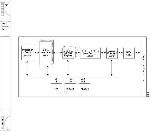
The ONS 15454 DS1-14 card provides 14 Telcordia-compliant, GR-499 DS-1 ports. Each port operates at 1.544 Mbps over a 100 ohm twisted-pair copper cable. The DS1-14 card can function as a working or protect card in 1:1 protection schemes and as a working card in 1:N protection schemes. Figure 4-14 shows the DS1-14 faceplate and a block diagram of the card.
Figure 4-14 DS1-14 faceplate and block diagram
You can install the DS1-14 card in any multispeed or high-speed card slot on the ONS 15454. Each DS1-14 port has DSX-level (digital signal cross-connect frame) outputs supporting distances up to 655 feet.
The DS1-14 card supports 1:1 protection. The DS1-14 can be a working card in a 1:N protection scheme with the proper backplane EIA and wire-wrap or AMP Champ connectors. You can also provision the DS1-14 to monitor for line and frame errors in both directions.
You can group and map DS1-14 card traffic in STS-1 increments to any other card in an ONS 15454 except DS-3 cards. Each DS-1 is asynchronously mapped into a SONET VT1.5 payload and the card carries a DS-1 payload intact in a VT1.5. For performance monitoring purposes, you can gather bidirectional DS-1 frame-level information (loss of frame, parity errors, cyclic redundancy check [CRC] errors, etc.).
4.12.1 DS1-14 Hosted by XCVT
All 14 VT1.5 payloads from a DS1-14 card are carried in a single STS-1 to the XC or XCVT card where the payload is further aggregated for efficient STS-1 transport. XCVT cards host a maximum of 336 bidirectional VT1.5s.
4.12.2 DS1-14 Card-Level Indicators
The DS1-14 card faceplate has three LEDs.
4.12.3 DS1-14 Port-Level Indicators
You can obtain the status of the DS1-14 card ports using the LCD screen on the ONS 15454 fan-tray assembly. Use the LCD to view the status of any port or card slot; the screen displays the number and severity of alarms for a given port or slot. See Chapter 1, "Alarm Troubleshooting" for a complete description of the alarm messages.
4.12.4 DS1-14 Specifications
•
–
–
–
–
–
–
–
•
–
–
–
–
–
–
–
–
1544 KHz–
–
–
•
–
–
C-Temp (15454-DS1-14): 0 to +55 degrees Celsius
I-Temp (15454-DS1-14-T): -40 to +65 degrees Celsius
Note
The I-Temp symbol is displayed on the faceplate of an I-Temp compliant card. A card without this symbol is C-Temp compliant.
–
–
•
–
–
–
–
•
–
4.13 DS1N-14 Card
The DS1N-14 card provides 14 Telcordia-compliant, GR-499 DS-1 ports. Each DS1N-14 port operates at 1.544 Mbps over a 100 ohm twisted-pair copper cable. Figure 4-15 shows the DS1N-14 faceplate and a block diagram of the card.
Figure 4-15 DS1N-14 faceplate and block diagram
Each DS1N-14 port features DSX-level outputs supporting distances up to 655 feet depending on facility conditions.
The DS1N-14 card supports 1:N (N<5) protection with the proper backplane EIA and wire-wrap or AMP Champ connectors. You can also provision the DS1N-14 to monitor line and frame errors in both directions.
The DS1N-14 card can function as a working or protect card in 1:1 or 1:N protection schemes. If you use the DS1N-14 as a standard DS-1 card in a 1:1 protection group, you can install the DS1N-14 card in any multispeed or high-speed card slot on the ONS 15454. If you use the card's 1:N functionality, you must install a DS1N-14 card in Slots 3 and 15.
You can group and map DS1N-14 card traffic in STS-1 increments to any other card in an ONS 15454 node. Each DS-1 is asynchronously mapped into a SONET VT1.5 payload and the card carries a DS-1 payload intact in a VT1.5. For performance-monitoring purposes, you can gather bidirectional DS-1 frame-level information (loss of frame, parity errors or CRC errors, for example).
4.13.1 DS1N-14 Hosted by XCVT
All 14 VT1.5 payloads from a DS1N-14 card are carried in a single STS-1 to the XC or XCVT card where the payload is further aggregated for efficient STS-1 transport. XCVT cards host a maximum of 336 bidirectional VT1.5s.
4.13.2 DS1N-14 Card-Level Indicators
The DS1N-14 card faceplate has three LEDs.
4.13.3 DS1N-14 Port-Level Indicators
You can obtain the status of the 14 DS-1 ports using the LCD screen on the ONS 15454 fan-tray assembly. Use the LCD to view the status of any port or card slot; the screen displays the number and severity of alarms for a given port or slot. See Chapter 1, "Alarm Troubleshooting" for a complete description of the alarm messages.
4.13.4 DS1N-14 Specifications
•
–
–
–
–
–
–
–
•
–
–
–
–
–
–
–
–
1544 KHz–
–
–
•
–
–
C-Temp (15454-DS1N-14): 0 to +55 degrees Celsius
I-Temp (15454-DS1N-14-T): -40 to +65 degrees Celsius
Note
The I-Temp symbol is displayed on the faceplate of an I-Temp compliant card. A card without this symbol is C-Temp compliant.
–
–
•
–
–
–
–
•
–
4.14 DS3-12 Card
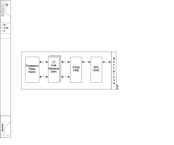
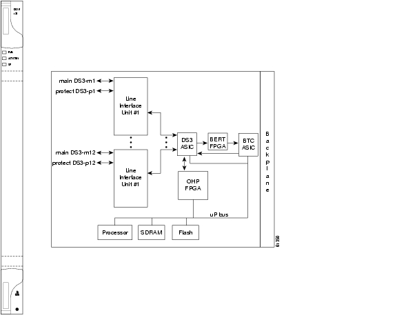
The ONS 15454 DS3-12 card provides 12 Telcordia-compliant, GR-499 DS-3 ports per card. Each port operates at 44.736 Mbps over a single 75 ohm 728A or equivalent coaxial span. The DS3-12 card operates as a working or protect card in 1:1 protection schemes and as a working card in 1:N protection schemes. Figure 4-16 shows the DS3-12 faceplates, and a block diagram of the card.
Figure 4-16 DS3-12 faceplate and block diagram
You can install the DS3-12 card in any multispeed or high-speed card slot on the ONS 15454. Each DS3-12 card port features DSX-level outputs supporting distances up to 450 feet depending on facility conditions.
The DS3-12 card supports 1:1 protection with the proper backplane EIA. EIAs are available with BNC or SMB connectors. For more information, see the "Electrical Card Protection and the Backplane" section.
Caution
4.14.1 DS3-12 Card-Level Indicators
The DS3-12 card faceplate has three LEDs.
4.14.2 DS3-12 Port-Level Indicators
You can find the status of the 12 DS3-12 card ports using the LCD screen on the ONS 15454 fan-tray assembly. Use the LCD to view the status of any port or card slot; the screen displays the number and severity of alarms for a given port or slot. See Chapter 1, "Alarm Troubleshooting" for a complete description of the alarm messages.
4.14.3 DS3-12 Specifications
•
–
–
–
–
–
–
–
•
–
–
–
–
–
–
–
–
–
–
–
•
–
•
–
C-Temp (15454-DS3-12): 0 to +55 degrees Celsius
I-Temp (15454-DS3-12-T): -40 to +65 degrees Celsius
Note
The I-Temp symbol is displayed on the faceplate of an I-Temp compliant card. A card without this symbol is C-Temp compliant.
–
–
•
–
–
–
–
•
–
4.15 DS3N-12 Card
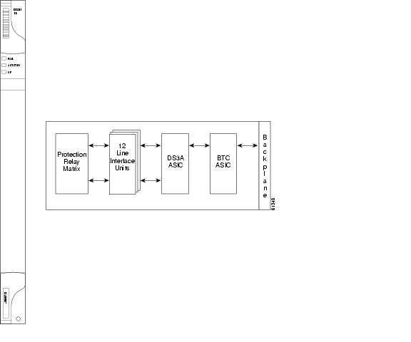
The ONS 15454 DS3N-12 card provides 12 Telcordia-compliant, TR499 DS-3 ports per card. Each port operates at 44.736 Mbps over a single 75 ohm 728A or equivalent coaxial span. Figure 4-17 shows the DS3N-12 faceplate and a diagram of the card.
Figure 4-17 DS3N-12 faceplate and block diagram
You can install the DS3N-12 card in any multispeed or high-speed card slot. Each DS3N-12 card port features DSX-level outputs supporting distances up to 450 feet depending on facility conditions. With the proper backplane EIA, the card supports BNC or SMB connectors.
The DS3N-12 can operate as the protect card in a 1:N (N<5) DS-3 protection group. It has additional circuitry not present on the basic DS3-12 card that allows it to protect up to five working DS3-12 cards. The basic DS3-12 card can only function as the protect card for one other DS3-12 card. Other than the protection capabilities, the DS3-12 and DS3N-12 cards are identical.
4.15.1 DS3N-12 Card-Level Indicators
The DS3N-12 card faceplate has three LEDs.
4.15.2 DS3N-12 Port-Level Indicators
You can find the status of the 12 DS3N-12 card ports using the LCD screen on the ONS 15454 fan-tray assembly. Use the LCD to quickly view the status of any port or card slot; the screen displays the number and severity of alarms for a given port or slot. See Chapter 1, "Alarm Troubleshooting" for a complete description of the alarm messages.
4.15.3 DS3N-12 Card Specifications
•
–
–
–
–
–
–
–
•
–
–
–
–
–
–
–
–
–
–
–
–
•
–
•
–
C-Temp (15454-DS3N-12): 0 to +55 degrees Celsius
I-Temp (15454-DS3N-12-T): -40 to +65 degrees Celsius
Note
The I-Temp symbol is displayed on the faceplate of an I-Temp compliant card. A card without this symbol is C-Temp compliant.
–
–
•
–
–
–
–
•
–
4.16 DS3-12E Card
The ONS 15454 DS3-12E card provides 12 Telcordia-compliant ports per card. Each port operates at 44.736 Mbps over a single 75 ohm 728A or equivalent coaxial span. The DS3-12E card provides enhanced performance monitoring functions. The DS3-12E can detect several different errored logic bits within a DS-3 frame. This function allows the ONS 15454 to identify a degrading DS-3 facility caused by upstream electronics (DS-3 Framer). In addition, DS3 frame format auto detection and J1 path trace are supported. By monitoring additional overhead in the DS-3 frame, subtle network degradations can be detected. Figure 4-18 shows the DS3-12E faceplate and a diagram of the card.
Figure 4-18 DS3-12E faceplate and block diagram
The following list summarizes DS3-12E card features:
•
•
•
•
•
•
•
•
•
•
You can install the DS3-12E card in any multispeed or high-speed card slot on the ONS 15454. Each DS3-12E port features DSX-level outputs supporting distances up to 450 feet. With the proper backplane EIA, the card supports BNC or SMB connectors.
The DS3-12E supports a 1:1 protection scheme, meaning it can operate as the protect card for one other DS3-12E card.
4.16.1 DS3-12E Card-Level Indicators
The DS3-12E card faceplate has three LEDs.
4.16.2 DS3-12E Port-Level Indicators
You can find the status of the DS3-12E card ports using the LCD screen on the ONS 15454 fan-tray assembly. Use the LCD to quickly view the status of any port or card slot; the screen displays the number and severity of alarms for a given port or slot. See Chapter 1, "Alarm Troubleshooting" for a complete description of the alarm messages.
4.16.3 DS3-12E Compatibility
The DS3-12E is compatible with Software R2.2.x or higher. If Software R3.0 or higher is used, the card uses all enhanced performance monitoring functions. With Software R2.2.2, the DS-3E card operates with the same functions as the older DS-3 card.
4.16.4 DS3-12E Card Specifications
•
–
–
–
–
–
–
–
•
–
–
–
–
–
–
–
–
–
–
–
–
•
–
•
–
I-Temp (15454-DS3-12E-T): -40 to +65 degrees Celsius
Note
The I-Temp symbol is displayed on the faceplate of an I-Temp compliant card. A card without this symbol is C-Temp compliant.
–
–
•
–
–
–
•
–
4.17 DS3N-12E Card
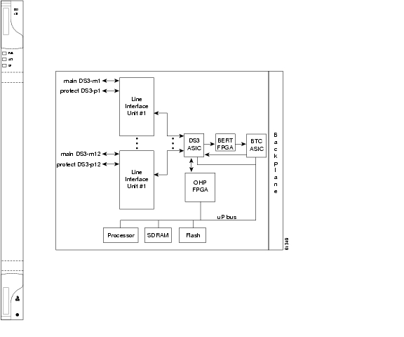
The ONS 15454 DS3N-12E card provides 12 Telcordia-compliant ports per card. Each port operates at 44.736 Mbps over a single 75 ohm 728A or equivalent coaxial span. The DS3N-12E card provides enhanced performance monitoring functions. The DS3N-12E can detect several different errored logic bits within a DS-3 frame. This function allows the ONS 15454 to identify a degrading DS-3 facility caused by upstream electronics (DS-3 Framer). In addition, DS3 frame format auto detection and J1 path trace are supported. By monitoring additional overhead in the DS-3 frame, subtle network degradations can be detected. Figure 4-19 shows the DS3N-12E faceplate and a diagram of the card.
Figure 4-19 DS3N-12E faceplate and block diagram
The following list summarizes the DS3N-12E card features:
•
•
•
•
•
•
•
•
•
•
You can install the DS3N-12E card in any multispeed or high-speed card slot. Each DS3N-12E port features DSX-level outputs supporting distances up to 450 feet. With the proper backplane EIA, the card supports BNC or SMB connectors.
The DS3N-12E can operate as the protect card in a 1:N (N<5) DS-3 protection group. It has additional circuitry not present on the basic DS3-12E card that allows it to protect up to five working DS3-12E cards. The basic DS3-12E card can only function as the protect card for one other DS3-12E card.
4.17.1 DS3N-12E Card-Level Indicators
The DS3N-12E card faceplate has three LEDs.
4.17.2 DS3N-12E Port-Level Indicators
You can find the status of the DS3N-12E card ports using the LCD screen on the ONS 15454 fan-tray assembly. Use the LCD to view the status of any port or card slot; the screen displays the number and severity of alarms for a given port or slot. See Chapter 1, "Alarm Troubleshooting" for a complete description of the alarm messages.
4.17.3 DS3N-12E Compatibility
The DS3N-12E cards are compatible with Software R2.2.x or higher. If Software R3.0 or higher is used, the DS3N-12E operates using all enhanced performance monitoring functions. With Software R2.2.2, the DS3N-12E operates with the same functions as the older DS-3 card.
4.17.4 DS3N-12E Card Specifications
•
–
–
–
–
–
–
–
•
–
–
–
–
–
–
–
–
–
–
–
–
•
–
•
–
I-Temp (15454-DS3N-12E-T): -40 to +65 degrees Celsius
Note
The I-Temp symbol is displayed on the faceplate of an I-Temp compliant card. A card without this symbol is C-Temp compliant.
–
–
•
–
–
–
•
–
4.18 DS3XM-6 Card
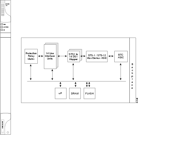
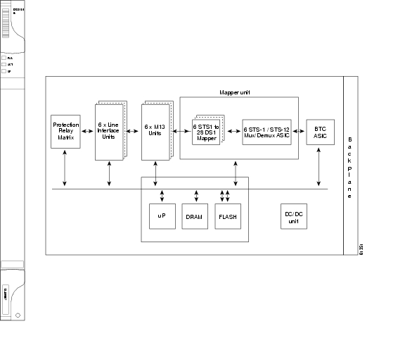
The DS3XM-6 card, commonly referred to as a transmux card, provides six Telcordia-compliant, GR-499-CORE M13 multiplexing functions. The DS3XM-6 converts six framed DS-3 network connections to 28x6 or 168 VT1.5s. Figure 4-20 shows the DS3XM-6 faceplate and a block diagram of the card.
Figure 4-20 DS3XM-6 faceplate and block diagram
Note
You can install the DS3XM-6 in any multispeed or high-speed card slot. Each DS3XM-6 port features DSX-level outputs supporting distances up to 450 feet depending on facility conditions. The DS3XM-6 card supports 1:1 protection with the proper backplane EIA. EIAs are available with BNC or SMB connectors.
4.18.1 DS3XM-6 Hosted By XCVT
The DS3XM-6 card works in conjunction with the XCVT card. A single DS3XM-6 can demultiplex (map down to a lower rate) six DS-3 signals into 168 VT1.5s that the XCVT card then manages and cross connects. XCVT cards host a maximum of 336 bidirectional VT1.5s or two DS3XM-6 cards. In most network configurations two DS3XM-6 cards are paired together as working and protect cards.
4.18.2 DS3XM-6 Card-Level Indicators
The DS3XM-6 card faceplate has three LEDs.
4.18.3 DS3XM-6 Port-Level Indicators
You can find the status of the six DS3XM-6 card ports using the LCD screen on the ONS 15454 fan-tray assembly. Use the LCD to quickly view the status of any port or card slot; the screen displays the number and severity of alarms for a given port or slot. See Chapter 1, "Alarm Troubleshooting" for a complete description of the alarm messages.
4.18.4 DS3XM-6 Card Specifications
•
–
–
–
–
–
–
•
–
–
–
–
–
–
–
–
–
–
–
–
–
•
–
•
–
C-Temp (15454-DS3XM-6): 0 to +55 degrees Celsius
I-Temp (15454-DS3XM-6-T): -40 to +65 degrees Celsius
Note
The I-Temp symbol is displayed on the faceplate of an I-Temp compliant card. A card without this symbol is C-Temp compliant.
–
–
•
–
–
–
–
•
–
4.19 OC3 IR 4/STM1 SH 1310 Card
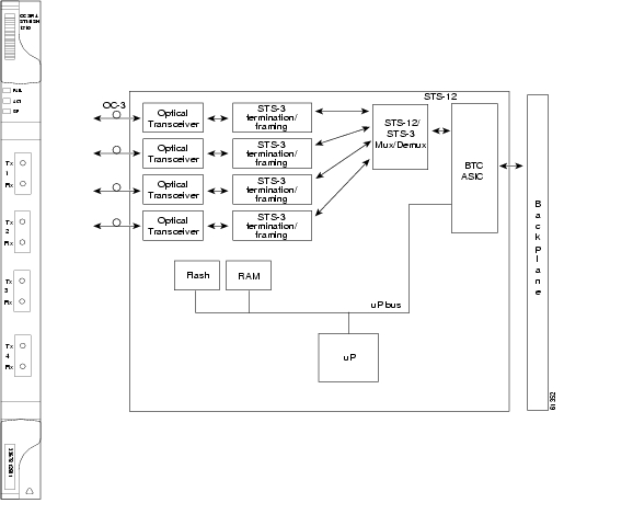
The OC3 IR 4/STM1 SH 1310 card provides four intermediate or short range SONET/SDH OC-3 ports compliant with the International Telecommunication Union's G.707, G.957, and Telcordia's GR-253. Each port operates at 155.52 Mbps over a single-mode fiber span. The card supports VT and non-concatenated or concatenated payloads at the STS-1 or STS-3c signal levels. Figure 4-21 shows the OC3 IR 4/STM1 SH 1310 faceplate and a diagram of the card.
Note
Figure 4-21 OC3 IR 4/STM1 SH 1310 faceplate and block diagram
You can install the OC3 IR 4/STM1 SH 1310 card in any multispeed or high-speed card slot. The card can be provisioned as part of a unidirectional path switched ring (UPSR) or in a linear add-drop multiplexer (ADM) configuration. Each port features a 1310 nm laser and contains a transmit and receive connector (labeled) on the card faceplate. The card uses SC connectors.
The OC3 IR 4/STM1 SH 1310 card supports 1+1 unidirectional or bidirectional protection switching. You can provision protection on a per port basis. See the "Optical Card Protection" section, for more information.
The OC3 IR 4/STM1 SH 1310 detects LOS, LOF, Loss of Pointer (LOP), line Alarm Indication Signal (AIS-L), and line Remote Defect Indication (RDI-L) conditions. See Chapter 1, "Alarm Troubleshooting" for a description of these conditions. The card also counts section and line bit interleaved parity (BIP) errors.
4.19.1 OC3 IR 4/STM1 SH 1310 Card-Level Indicators
The OC3 IR 4/STM1 SH 1310 card has three card-level LED indicators.
4.19.2 OC3 IR 4/STM1 SH 1310 Port-Level Indicators
You can find the status of the four card ports using the LCD screen on the ONS 15454 fan-tray assembly. Use the LCD to view the status of any port or card slot; the screen displays the number and severity of alarms for a given port or slot. See Chapter 1, "Alarm Troubleshooting" for a complete description of the alarm messages.
Warning
4.19.3 OC3 IR 4/STM1 SH 1310 Card Specifications
•
–
–
–
–
–
–
–
–
–
–
–
–
•
–
–
–
–
•
–
C-Temp (15454-OC34IR1310): 0 to +55 degrees Celsius
I-Temp (15454-OC34I13-T): -40 to +65 degrees Celsius
Note
The I-Temp symbol is displayed on the faceplate of an I-Temp compliant card. A card without this symbol is C-Temp compliant.
–
–
•
–
–
–
–
•
–
–
4.20 OC12 IR/STM4 SH 1310 Card
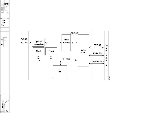
The OC12 IR/STM4 SH 1310 card provides one intermediate or short range SONET/SDH OC-12 port compliant with the International Telecommunication Union's G.707, G.957, and Telcordia's GR-253. The port operates at 622.08 Mbps over a single-mode fiber span. The card supports VT and non-concatenated or concatenated payloads at STS-1, STS-3c, STS-6c or STS-12c signal levels. Figure 4-22 shows the OC12 IR/STM4 SH 1310 faceplate and a block diagram of the card.
Note
Figure 4-22 OC12 IR/STM4 SH 1310 faceplate and block diagram
You can install the OC12 IR/STM4 SH 1310 card in any multispeed or high-speed card slot and provision the card as a drop card or span card in a two-fiber BLSR, UPSR, or in ADM (linear) configurations.
The OC12 IR/STM4 SH 1310 port features a 1310 nm laser and contains a transmit and receive connector (labeled) on the card faceplate. The OC12 IR/STM4 SH 1310 uses SC optical connections and supports 1+1 unidirectional and bidirectional protection.
The OC12 IR/STM4 SH 1310 detects LOS, LOF, LOP, AIS-L, and RDI-L conditions. See Chapter 1, "Alarm Troubleshooting" for a description of these conditions. The card counts section and line BIT errors.
4.20.1 OC12 IR/STM4 SH 1310 Card-Level Indicators
The OC12 IR/STM4 SH 1310 card has three card-level LED indicators.
4.20.2 OC12 IR/STM4 SH 1310 Port-Level Indicators
You can find the status of the OC-12 card port using the LCD screen on the ONS 15454 fan-tray assembly. Use the LCD to view the status of any port or card slot; the screen displays the number and severity of alarms for a given port or slot. See Chapter 1, "Alarm Troubleshooting" for a complete description of the alarm messages.
Warning
4.20.3 OC12 IR/STM4 SH 1310 Card Specifications
•
–
–
–
–
–
–
•
–
–
–
–
–
•
–
–
–
–
•
–
C-Temp (15454-OC121IR1310): 0 to +55 degrees Celsius
I-Temp (15454-OC121I13-T): -40 to +65 degrees Celsius
Note
The I-Temp symbol is displayed on the faceplate of an I-Temp compliant card. A card without this symbol is C-Temp compliant.
–
–
•
–
–
–
–
•
–
–
4.21 OC12 LR/STM4 LH 1310 Card
The OC12 LR/STM4 LH 1310 card provides one long-range, ITU-T G.707, ITU-T G.957, and Telcordia-compliant, GR-253 SONET OC-12 port per card. The port operates at 622.08 Mbps over a single-mode fiber span. The card supports VT and non-concatenated or concatenated payloads at STS-1, STS-3c, STS-6c or STS-12c signal levels. Figure 4-23 shows the OC12 LR/STM4 LH 1310 faceplate and a block diagram of the card.
Note
Figure 4-23 OC12 LR/STM4 LH 1310 faceplate and block diagram
You can install the OC12 LR/STM4 LH 1310 card in any multispeed or high-speed card slot and provision the card as a drop card or span card in a two-fiber BLSR (Bidirectional line switched ring), UPSR, or ADM (linear) configuration.
The OC12 LR/STM4 LH 1310 card port features a 1310 nm laser and contains a transmit and receive connector (labeled) on the card faceplate. The card uses SC optical connections supporting 1+1 unidirectional and bidirectional protection.
The OC12 LR/STM4 LH 1310 detects LOS, LOF, LOP, AIS-L, and RDI-L conditions. See Chapter 1, "Alarm Troubleshooting" for a description of these conditions. The card also counts section and line BIT errors.
4.21.1 OC12 LR/STM4 LH 1310 Card-Level Indicators
The OC12 LR/STM4 LH 1310 card has three card-level LED indicators.
4.21.2 OC12 LR/STM4 LH 1310 Port-Level Indicators
You can find the status of the OC12 LR/STM4 LH 1310 card port using the LCD screen on the ONS 15454 fan-tray assembly. Use the LCD to quickly view the status of any port or card slot; the screen displays the number and severity of alarms for a given port or slot. See Chapter 1, "Alarm Troubleshooting" for a complete description of the alarm messages.
Warning
4.21.3 OC12 LR/STM4 LH 1310 Card Specifications
•
–
–
–
–
–
–
•
–
–
–
–
–
•
–
–
–
–
•
–
C-Temp (15454-OC121LR1310): 0 to +55 degrees Celsius
I-Temp (15454-OC121L13-T): -40 to +65 degrees Celsius
Note
The I-Temp symbol is displayed on the faceplate of an I-Temp compliant card. A card without this symbol is C-Temp compliant.
–
–
•
–
–
–
–
•
–
–
4.22 OC12 LR/STM4 LH 1550 Card
The OC12 LR/STM4 LH 1550 card provides one long-range SONET/SDH OC-12 port compliant with the International Telecommunication Union's G.707, G.957, and Telcordia's GR-253. The port operates at 622.08 Mbps over a single-mode fiber span. The card supports VT and non-concatenated, or concatenated payloads at STS-1, STS-3c, STS-6c, or STS-12c signal levels. Figure 4-24 shows the OC12 LR/STM4 LH 1550 faceplate and a block diagram of the card.
Note
Figure 4-24 OC12 LR/STM4 LH 1550 faceplate and block diagram
You can install the OC12 LR/STM4 LH 1550 card in any multispeed card slot. The OC12 LR/STM4 LH 1550 can be provisioned as part of a two-fiber BLSR, UPSR or linear ADM.
The OC12 LR/STM4 LH 1550 uses long-reach optics centered at 1550 nm and contains a transmit and receive connector (labeled) on the card faceplate. The OC12 LR/STM4 LH 1550 uses SC optical connections and supports 1+1 bidirectional or unidirectional protection switching.
The OC12 LR/STM4 LH 1550 detects LOS, LOF, LOP, AIS-L, and RDI-L conditions. See Chapter 1, "Alarm Troubleshooting" for a description of these conditions. The card also counts section and line BIT errors.
4.22.1 OC12 LR/STM4 LH 1550 Card-Level Indicators
The OC12 LR/STM4 LH 1550 card has three card-level LED indicators.
4.22.2 OC12 LR/STM4 LH 1550 Port-Level Indicators
You can find the status of the OC12 LR/STM4 LH 1550 card port using the LCD screen on the ONS 15454 fan-tray assembly. Use the LCD to view the status of any port or card slot; the screen displays the number and severity of alarms for a given port or slot. See Chapter 1, "Alarm Troubleshooting" for a complete description of the alarm messages.
Warning
4.22.3 OC12 LR/STM4 LH 1550 Card Specifications
•
–
–
–
–
–
–
•
–
–
–
–
–
•
–
–
–
–
•
–
C-Temp (15454-OC121LR1550): 0 to +55 degrees Celsius
I-Temp (15454-OC121L15-T): -40 to +65 degrees Celsius
Note
The I-Temp symbol is displayed on the faceplate of an I-Temp compliant card. A card without this symbol is C-Temp compliant.
–
–
•
–
–
–
–
•
–
–
4.23 OC48 IR 1310 Card
The OC48 IR 1310 card provides one intermediate-range, Telcordia-compliant, GR-253 SONET OC-48 port per card. Each port operates at 2.49 Gbps over a single-mode fiber span. The card supports VT and non-concatenated, or concatenated payloads at STS-1, STS-3c, STS-6c, STS-12c, or STS-48c signal levels. Figure 4-25 shows the OC48 IR 1310 faceplate and a block diagram of the card.
Figure 4-25 OC48 IR 1310 faceplate and block diagram
You can install the OC48 IR 1310 card in any high-speed card slot and provision the card as a drop or span card in a two-fiber or four-fiber BLSR, UPSR, or in an ADM (linear) configuration.
The OC-48 port features a 1310 nm laser and contains a transmit and receive connector (labeled) on the card faceplate. The OC48 IR 1310 uses SC connectors. The card supports 1+1 unidirectional and bidirectional protection switching.
The OC48 IR 1310 detects LOS, LOF, LOP, AIS-L, and RDI-L conditions. See Chapter 1, "Alarm Troubleshooting" for a description of these conditions. The card also counts section and line BIT errors.
4.23.1 OC48 IR 1310 Card-Level Indicators
The OC48 IR 1310 card has three card-level LED indicators.
4.23.2 OC48 IR 1310 Port-Level Indicators
You can find the status of the OC48 IR 1310 card port using the LCD screen on the ONS 15454 fan-tray assembly. Use the LCD to view the status of any port or card slot; the screen displays the number and severity of alarms for a given port or slot. See Chapter 1, "Alarm Troubleshooting" for a complete description of the alarm messages.
Warning
4.23.3 OC48 IR 1310 Card Specifications
•
–
–
–
–
–
–
•
–
–
–
–
Transmitter: Uncooled direct modulated DFB
•
–
–
–
–
•
–
C-Temp (15454-OC481IR1310): 0 to +55 degrees Celsius
–
–
•
–
–
–
–
•
–
–
4.24 OC48 LR 1550 Card
The OC48 LR 1550 card provides one long-range, Telcordia-compliant, GR-253 SONET OC-48 port per card. Each port operates at 2.49 Gbps over a single-mode fiber span. The card supports VT, non-concatenated or concatenated payloads at STS-1, STS-3c, STS-6c STS-12c or STS-48c signal levels. Figure 4-26 shows the OC48 LR 1550 faceplate and a block diagram of the card.
Figure 4-26 OC48 LR 1550 faceplate and block diagram
You can install OC48 LR 1550 cards in any high-speed slot on the ONS 15454 and provision the card as a drop or span card in a two-fiber or four-fiber BLSR, UPSR, or in an ADM (linear) configuration.
The OC48 LR 1550 port features a 1550 nm laser and contains a transmit and receive connector (labeled) on the card faceplate. The card uses SC connectors, and it supports 1+1 unidirectional and bidirectional protection switching.
The OC48 LR 1550 detects LOS, LOF, LOP, AIS-L, and RDI-L conditions. See Chapter 1, "Alarm Troubleshooting" for a description of these conditions. The card also counts section and line BIT errors.
4.24.1 OC48 LR 1550 Card-Level Indicators
The OC48 LR 1550 card has three card-level LED indicators.
4.24.2 OC48 LR 1550 Port-Level Indicators
You can find the status of the OC48 LR 1550 card port using the LCD screen on the ONS 15454 fan-tray assembly. Use the LCD to view the status of any port or card slot; the screen displays the number and severity of alarms for a given port or slot. See Chapter 1, "Alarm Troubleshooting" for a complete description of the alarm messages.
Warning
4.24.3 OC48 LR 1550 Card Specifications
•
–
–
–
–
–
–
•
–
–
–
–
–
•
–
–
–
–
•
–
C-Temp (15454-OC481LR1550): 0 to +55 degrees Celsius
–
–
•
–
–
–
–
•
–
–
4.25 OC48 IR/STM16 SH AS 1310 Card
The OC48 IR/STM16 SH AS 1310 card provides one intermediate-range SONET/SDH OC-48 port compliant with the International Telecommunication Union's G.707, G.957, and Telcordia's GR-253. The port operates at 2.49 Gbps over a single-mode fiber span. The card supports VT and non-concatenated or concatenated payloads at STS-1, STS-3c, STS-6c, STS-12c, or STS-48c signal levels. Figure 4-27 shows the OC48 IR/STM16 SH AS 1310 faceplate and a block diagram of the card.
Figure 4-27 OC48 IR/STM16 SH AS 1310 faceplate and block diagram
You can install the OC48 IR/STM16 SH AS 1310 card in any multispeed or high-speed card slot on the ONS 15454 and provision the card as a drop or span card in a two-fiber or four-fiber BLSR, UPSR, or in an ADM (linear) configuration.
The OC-48 port features a 1310 nm laser and contains a transmit and receive connector (labeled) on the card faceplate. The OC48 IR/STM16 SH AS 1310 uses SC connectors. The card supports 1+1 unidirectional and bidirectional protection switching.
The OC48 IR/STM16 SH AS 1310 detects LOS, LOF, LOP, AIS-L, and RDI-L conditions. See Chapter 1, "Alarm Troubleshooting" for a description of these conditions. The card also counts section and line BIT errors.
4.25.1 OC48 IR/STM16 SH AS 1310 Card-Level Indicators
The OC48 IR/STM16 SH AS 1310 card has three card-level LED indicators.
4.25.2 OC48 IR/STM16 SH AS 1310 Port-Level Indicators
You can find the status of the OC48 IR/STM16 SH AS 1310 card port using the LCD screen on the ONS 15454 fan-tray assembly. Use the LCD to view the status of any port or card slot; the screen displays the number and severity of alarms for a given port or slot. See Chapter 1, "Alarm Troubleshooting" for a complete description of the alarm messages.
Warning
4.25.3 OC48 IR/STM16 SH AS 1310 Compatibility
Use the XC10G card, the TCC+ card, the new 15454-SA-ANSI shelf assembly, and Software R3.1 or higher to enable the OC48 IR/STM16 SH AS 1310 card. The OC48 IR/STM16 SH AS 1310 card uses the BTC backplane interface to provide recognition in both the high-speed and multispeed slots.
4.25.4 OC48 IR/STM16 SH AS 1310 Card Specifications
•
–
–
–
–
–
–
•
–
–
–
–
–
•
–
–
–
–
•
–
C-Temp (15454-OC481IR1310A): 0 to +55 degrees Celsius
–
–
•
–
–
–
–
•
–
–
4.26 OC48 LR/STM16 LH AS 1550 Card
The OC48 LR/STM16 LH AS 1550 card provides one long-range SONET/SDH OC-48 port compliant with the International Telecommunication Union's G.707, G.957, and Telcordia's GR-253. Each port operates at 2.49 Gbps over a single-mode fiber span. The card supports VT and non-concatenated or concatenated payloads at STS-1, STS-3c, STS-6c, STS-12c, or STS-48c signal levels. Figure 4-28 shows the OC48 LR/STM16 LH AS 1550 faceplate and a block diagram of the card.
Figure 4-28 OC48 LR/STM16 LH AS 1550 faceplate and block diagram
You can install OC48 LR/STM16 LH AS 1550 cards in any multispeed or high-speed slot on the ONS 15454 and provision the card as a drop or span card in a two-fiber or four-fiber BLSR, UPSR, or in an ADM (linear) configuration.
The OC48 LR/STM16 LH AS 1550 port features a 1550 nm laser and contains a transmit and receive connector (labeled) on the card faceplate. The card uses SC connectors, and it supports 1+1 unidirectional and bidirectional protection switching.
The OC48 LR/STM16 LH AS 1550 detects LOS, LOF, LOP, AIS-L, and RDI-L conditions. See Chapter 1, "Alarm Troubleshooting" for a description of these conditions. The card also counts section and line BIT errors.
4.26.1 OC48 LR/STM16 LH AS 1550 Card-Level Indicators
The OC48 LR/STM16 LH AS 1550 card has three card-level LED indicators.
4.26.2 OC48 LR/STM16 LH AS 1550 Port-Level Indicators
You can find the status of the OC48 LR/STM16 LH AS 1550 card port using the LCD screen on the ONS 15454 fan-tray assembly. Use the LCD to view the status of any port or card slot; the screen displays the number and severity of alarms for a given port or slot. See Chapter 1, "Alarm Troubleshooting" for a complete description of the alarm messages.
Warning
4.26.3 OC48 LR/STM16 LH AS 1550 Compatibility
Use the XC10G card, the TCC+ card, the new 15454-SA-ANSI shelf assembly, and Software R3.1 or higher to enable the OC48 LR/STM16 LH AS 1550 card. The OC48 LR/STM16 LH AS 1550 card uses the BTC backplane interface to provide recognition in both the high-speed and multispeed slots.
4.26.4 OC48 LR/STM16 LH AS 1550 Card Specifications
•
–
–
–
–
–
–
•
–
–
–
–
–
•
–
–
–
–
•
–
C-Temp (15454-OC481LR1550A): 0 to +55 degrees Celsius
–
–
•
–
–
–
–
•
–
–
4.27 OC48 ELR/STM16 EH 100 GHz Cards
Thirty-seven distinct OC48 ITU 100GHz dense wavelength division multiplexing (DWDM) cards provide the ONS 15454 DWDM channel plan. Each OC-48 DWDM card has one SONET OC-48/SDH STM-16 port that complies with Telcordia, GR-253 SONET, and the International Telecommunication Union's ITU-T G.692, and ITU-T G.958.
The port operates at 2.49 Gbps over a single-mode fiber span. The card carries VT, concatenated, and non-concatenated payloads at STS-1, STS-3c, STS-6c, STS-12c, or STS-48c signal levels. Figure 4-29 shows the OC48 ELR/STM16 EH 100 GHz faceplate and a block diagram of the card.
Figure 4-29 OC48 ELR/STM16 EH 100 GHz faceplate and block diagram
Nineteen of the cards operate in the blue band with spacing of 100 GHz on the ITU grid standard G.692 and Telcordia GR-2918-CORE, issue 2 (1528.77 nm, 1530.33 nm, 1531.12 nm, 1531.90 nm, 1532.68 nm, 1533.47 nm, 1534.25 nm, 1535.04 nm, 1535.82 nm, 1536.61 nm, 1538.19 nm, 1538.98 nm, 1539.77 nm, 1540.56 nm, 1541.35 nm, 1542.14 nm, 1542.94 nm, 1543.73 nm, 1544.53 nm).
The other eighteen cards operate in the red band with spacing of 100 GHz on the ITU grid (1546.12 nm, 1546.92 nm, 1547.72 nm, 1548.51 nm,1549.32 nm, 1550.12 nm, 1550.92 nm, 1551.72 nm, 1552.52 nm, 1554.13 nm, 1554.94 nm, 1555.75 nm, 1556.55 nm, 1557.36 nm, 1558.17 nm, 1558.98 nm, 1559.79 nm, 1560.61 nm). These cards are also designed to interoperate with the Cisco ONS 15216 DWDM solution.
You can install the OC48 ELR/STM16 EH 100 GHz cards in any high-speed slot and provision the card as a drop or span card in a two-fiber or four-fiber BLSR, UPSR, or in an ADM (linear) configuration. Each OC48 ELR/STM16 EH 100 GHz card uses extended long reach optics operating individually within the ITU-T 100 GHz grid. The OC-48 DWDM cards are intended to be used in applications with long unregenerated spans of up to 200 km (with mid-span amplification). These transmission distances are achieved through the use of inexpensive optical amplifiers (flat gain amplifiers) such as Cisco ONS 15216 erbium-doped fiber amplifiers (EDFAs).
Maximum system reach in filterless applications is 26 dB without the use of optical amplifiers or regenerators. However, system reach also depends on the condition of the facilities, number of splices and connectors, and other performance-affecting factors. When used in combination with ONS 15216 100 GHz filters, the link budget is reduced by the insertion loss of the filters plus an additional 2dB power penalty. The OC-48 ELR DWDM cards wavelength stability is +/- 0.12 nm for the life of the product and over the full range of operating temperatures. Each interface contains a transmitter and receiver.
The OC-48 ELR cards detect loss of signal (LOS), loss of frame (LOF), loss of pointer (LOP), and line-layer alarm indication signal (AIS-L) conditions. See Chapter 1, "Alarm Troubleshooting" for a description of these conditions. The cards also count section and line BIT errors.
4.27.1 OC48 ELR 100 GHz Card-Level Indicators
The OC48 ELR/STM16 EH 100 GHz cards have three card-level LED indicators.
4.27.2 OC48 ELR 100 GHz Port-Level Indicators
You can find the status of the OC48 ELR card ports using the LCD screen on the ONS 15454 fan-tray assembly. Use the LCD to quickly view the status of any port or card slot; the screen displays the number and severity of alarms for a given port or slot. See Chapter 1, "Alarm Troubleshooting" for a complete description of the alarm messages.
Warning
4.27.3 OC48 ELR 100 GHz Compatibility
The OC48 ELR/STM16 EH 100 GHz card requires a cross-connect (XC) card, cross-connect virtual tributary (XCVT) card, or an XC10G for proper operation.
4.27.4 OC48 ELR 100 GHz Card Specifications
•
–
–
–
–
–
–
•
–
–
–
–
•
–
–
–
–
–
•
–
C-Temp: 0 to +55 degrees Celsius (For product names, see Card Temperature Ranges)
–
–
•
–
–
–
–
•
–
–
4.28 OC48 ELR 200 GHz Cards
Eighteen distinct OC48 ITU 200GHz dense wavelength division multiplexing (DWDM) cards provide the ONS 15454 DWDM channel plan. Each OC-48 DWDM card provides one Telcordia-compliant, GR-253 SONET OC-48 port. The port operates at 2.49 Gbps over a single-mode fiber span. The card carries VT, concatenated, and non-concatenated payloads at STS-1, STS-3c, STS-6c, STS-12c, or STS-48c signal levels. Figure 4-29 shows the OC48 ELR DWDM faceplate and a block diagram of the card.
Figure 4-30 OC48 ELR 200 GHz faceplate and block diagram
Nine of the cards operate in the blue band with spacing of 200 GHz on the ITU grid (1530.33 nm, 1531.90 nm, 1533.47 nm, 1535.04 nm, 1536.61 nm, 1538.19 nm, 1539.77 nm, 1541.35 nm, 1542.94 nm).
The other nine cards operate in the red band with spacing of 200 GHz on the ITU grid
(1547.72 nm, 1549.32 nm, 1550.92 nm, 1552.52 nm, 1554.13 nm, 1555.75 nm, 1557.36 nm, 1558.98 nm, 1560.61 nm). These cards are also designed to interoperate with the Cisco ONS 15216 DWDM solution.You can install the OC48 ELR 200 GHz cards in any high-speed slot and provision the card as a drop or span card in a two-fiber or four-fiber BLSR, UPSR, or in an ADM (linear) configuration. Each OC48 ELR DWDM card uses extended long reach optics operating individually within the ITU-T 200 GHz grid. The OC48 DWDM cards are intended to be used in applications with long unregenerated spans of up to 200 km (with mid-span amplification). These transmission distances are achieved through the use of inexpensive optical amplifiers (flat gain amplifiers) such as erbium doped fiber amplifiers (EDFAs). Using co-located amplification, distances up to 200 km can be achieved for a single channel (160 km for 8 channels).
Maximum system reach in filterless applications is 24 dB or approximately 80 km without the use of optical amplifiers or regenerators. However, system reach also depends on the condition of the facilities, number of splices and connectors or other performance-affecting factors. The OC48 ELR DWDM cards feature wavelength stability of +/- 0.25 nm. Each interface contains a transmitter and receiver.
The OC48 ELR DWDM cards are the first in a family of cards meant to support extended long reach applications in conjunction with optical amplification. Using electro-absorption technology, the OC48 DWDM cards provide a solution at the lower-extended long reach distances.
The OC48 LR 1550 interface features a 1550 nm laser and contains a transmit and receive connector (labeled) on the card faceplate. The card uses SC connectors and supports 1+1 unidirectional and bidirectional protection switching.
The OC48 ELR cards detect LOS, LOF, LOP, AIS-L, and RDI-L conditions. See Chapter 1, "Alarm Troubleshooting" for a description of these conditions. The cards also count section and line BIT errors.
To enable APS, the OC48 ELR cards extract the K1 and K2 bytes from the SONET overhead. The DCC bytes are forwarded to the TCC+ card; the TCC+ terminates the DCC.
4.28.1 OC48 ELR 200 GHz Card-Level Indicators
The OC48 ELR cards have three card-level LED indicators.
4.28.2 OC48 ELR 200 GHz Port-Level Indicators
You can find the status of the OC48 ELR card ports using the LCD screen on the ONS 15454 fan-tray assembly. Use the LCD to quickly view the status of any port or card slot; the screen displays the number and severity of alarms for a given port or slot. See Chapter 1, "Alarm Troubleshooting" for a complete description of the alarm messages.
Warning
4.28.3 OC48 ELR 200 GHz Compatibility
The OC48 ELR/STM16 EH 200 GHz card requires an XC card, XCVT card, or XC10G card for proper operation.
4.28.4 OC48 ELR 200 GHz Card Specifications
•
–
–
–
–
–
–
•
–
–
–
–
•
–
–
–
–
•
–
C-Temp: 0 to +55 degrees Celsius
–
–
•
–
–
–
–
•
–
–
4.29 OC192 LR/STM64 LH 1550 Card
The OC192 LR/STM64 LH 1550 card provides one long-range SONET/SDH OC-192 port compliant with the International Telecommunication Union's G.707, G.957, and Telcordia's GR-1377 and GR-253. The card port operates at 9.96 Gbps over unamplified distances up to 80 km with different types of fiber such as C-SMF or dispersion compensated fiber limited by loss and/or dispersion. The card supports VT and non-concatenated or concatenated payloads.
Figure 4-31 shows the OC192 LR/STM64 LH 1550 faceplate and a block diagram of the card. Figure 4-32 shows an enlarged view of the faceplate warning.
Figure 4-31 OC192 LR/STM64 LH 1550 faceplate and block diagram
Figure 4-32 Enlarged section of the OC192 LR/STM64 LH 1550 faceplate
Caution
You can install OC192 LR/STM64 LH 1550 cards in any high-speed slot on the ONS 15454 and provision the card as a drop or span card in a two-fiber or four-fiber BLSR, UPSR, or in an ADM (linear) configuration.
The OC-192 card port features a 1550 nm laser and contains a transmit and receive connector (labeled) on the card faceplate.
Warning
The card uses a dual SC connector for optical cable termination. The card supports 1+1 unidirectional and bidirectional facility protection. It also supports 1:1 protection in four-fiber bidirectional line switched ring applications where both span switching and ring switching may occur.
The OC192 LR/STM64 LH 1550 card detects SF, LOS, or LOF conditions on the optical facility. See Chapter 1, "Alarm Troubleshooting" for a description of these conditions. The card also counts section and line BIT errors from B1 and B2 byte registers in the section and line overhead.
4.29.1 OC192 LR/STM64 LH 1550 Card-Level Indicators
The OC192 LR/STM64 LH 1550 card has three card-level LED indicators.
4.29.2 OC192 LR/STM64 LH 1550 Port-Level Indicators
You can find the status of the OC192 LR/STM64 LH 1550 card port using the LCD screen on the ONS 15454 fan-tray assembly. Use the LCD to view the status of the port or card slot; the screen displays the number and severity of alarms for a given port or slot. See Chapter 1, "Alarm Troubleshooting" for a complete description of the alarm messages.
Warning
4.29.3 OC192 LR/STM64 LH 1550 Compatibility
Use the XC10G card, the TCC+ card, the new 15454-SA-ANSI shelf assembly, and Software R3.1 or higher to enable the OC192 LR/STM64 LH 1550 card.
4.29.4 OC192 LR/STM64 LH 1550 Card Specifications
•
–
–
–
•
Note
–
–
•
–
–
–
–
–
•
–
–
–
–
•
–
C-Temp (15454-OC192LR1550): 0 to +55 degrees Celsius
–
–
•
–
–
–
–
•
–
–
4.30 E100T-G Card
Use the E100T-G when the XC10G cross-connect card is in use. The ONS 15454 uses E100T-G cards for Ethernet (10 Mbps) and Fast Ethernet (100 Mbps). Each card provides 12 switched, IEEE 802.3-compliant, 10/100 Base-T Ethernet ports that can independently detect the speed of an attached device (auto-sense) and automatically connect at the appropriate speed. The ports auto-configure to operate at either half or full duplex and determine whether to enable or disable flow control. You can also configure Ethernet ports manually. Figure 4-33 shows the faceplate and a block diagram of the card.
Figure 4-33 E100T-G faceplate and block diagram
The E100T-G Ethernet card provides high-throughput, low-latency packet switching of Ethernet traffic across a SONET network while providing a greater degree of reliability through SONET "self-healing" protection services. This Ethernet capability enables network operators to provide multiple 10/100 Mbps access drops for high-capacity customer LAN interconnects, Internet traffic, and cable modem traffic aggregation. It enables the efficient transport and co-existence of traditional TDM traffic with packet-switched data traffic.
Each E100T-G card supports standards-based, wire-speed, layer 2 Ethernet switching between its Ethernet interfaces. The 802.1Q tag logically isolates traffic (typically subscribers). 802.1Q also supports multiple classes of service.
You can install the E100T-G card in any multispeed slot. Multiple Ethernet cards installed in an ONS 15454 can act independently or as a single Ethernet switch. You can create logical SONET ports by provisioning a number of STS channels to the packet switch entity within the ONS 15454. Logical ports can be created with a bandwidth granularity of STS-1. The ONS 15454 supports STS-1, STS-3c, STS-6c, or STS-12c circuit sizes.
Note
4.30.1 E100T-G Card-Level Indicators
The E100T-G card faceplate has two card-level LED indicators.
4.30.2 E100T-G Port-Level Indicators
The E100T-G card also has 12 pairs of LEDs (one pair for each port) to indicate port conditions. You can find the status of the E100T-G card port using the LCD screen on the ONS 15454 fan-tray assembly. Use the LCD to view the status of any port or card slot; the screen displays the number and severity of alarms for a given port or slot. See Chapter 1, "Alarm Troubleshooting" for a complete description of the alarm messages.
Table 4-42 E100T-G Port-Level Indicators
Transmitting and Receiving
Idle and Link Integrity
Inactive Connection or Unidirectional Traffic
4.30.3 E100T-G Compatibility
Use the E100T-G when the XC10G cross-connect card is in use.
4.30.4 E100T-G Card Specifications
•
–
C-Temp (15454-E100T-G): 0 to +55 degrees Celsius
–
–
•
–
–
•
–
4.31 E1000-2-G Card
Use the E1000-2-G when the XC10G cross-connect card is in use. The ONS 15454 uses E1000-2-G cards for Gigabit Ethernet (1000 Mbps). The E1000-2-G card provides two IEEE-compliant, 1000 Mbps ports for high-capacity customer LAN interconnections. Each port supports full-duplex operation. Figure 4-34 shows the card faceplate and a block diagram of the card.
The E1000-2-G card uses standard Cisco gigabit interface converter (GBIC) modular receptacles for the optical ports. GBICs are hot-swappable input/output devices that plug into a Gigabit Ethernet port to link the port to the fiber-optic network. Cisco provides two GBIC models: one for short-reach applications and one for long-reach applications. The short-reach model connects to multimode fiber and the long-reach model requires single-mode fiber.
For Software R2.2.0 and later, both GBIC modules are offered as separate orderable products: an IEEE 1000Base-SX compliant, 850 nm optical module and an IEEE 1000Base-LX-compliant, 1300 nm optical module, the 850 nm SX optics are designed for multimode fiber and distances of up to 220 meters on 62.5 micron fiber and up to 550 meters on 50 micron fiber. For more information see the Cisco ONS 15454 Installation and Operations Guide.
Figure 4-34 E1000-2-G faceplate and block diagram
The E1000-2-G Gigabit Ethernet card provides high-throughput, low-latency packet switching of Ethernet traffic across a SONET network while providing a greater degree of reliability through SONET "self-healing" protection services. This enables network operators to provide multiple 1000 Mbps access drops for high-capacity customer LAN interconnects. It enables efficient transport and co-existence of traditional TDM traffic with packet-switched data traffic.
Each E1000-2-G card supports standards-based, layer 2 Ethernet switching between its Ethernet interfaces and SONET interfaces on the ONS 15454. The 802.1Q VLAN tag logically isolates traffic (typically subscribers). The E1000-2-G supports two 802.1Q.
You can install the E1000-2-G card into any multispeed slot. Multiple Ethernet cards installed in an ONS 15454 can act together as a single switching entity or as an independent single switch supporting a variety of SONET port configurations.
You can create logical SONET ports by provisioning STS channels to the packet switch entity within the ONS 15454. Logical ports can be created with a bandwidth granularity of STS-1. The ONS 15454 supports STS-1, STS-3c, STS-6c, or STS-12c circuit sizes.
Note
4.31.1 E1000-2-G Card-Level Indicators
The E1000-2-G card faceplate has two card-level LED indicators.
4.31.2 E1000-2-G Port-Level Indicators
The E1000-2-G card also has one bicolor LED per port. When the green LINK LED is on, carrier is detected, meaning an active network cable is installed. When the green LINK LED is off, an active network cable is not plugged into the port, or the card is carrying unidirectional traffic. The amber port ACT LED flashes at a rate proportional to the level of traffic being received and transmitted over the port.
Table 4-44 E1000-2-G Port-Level Indicators
Transmitting and Receiving
Idle and Link Integrity
Inactive Connection or Unidirectional Traffic
4.31.3 E1000-2-G Compatibility
Use the E1000-2-G when the XC10G cross-connect card is in use.
4.31.4 E1000-2-G Card Specifications
•
–
C-Temp (15454-E1000-2-G): 0 to +55 degrees Celsius
–
–
•
–
–
–
–
•
–
–
4.32 E100T-12 Card
Do not use the E100T-12 when the XC10G cross-connect card is in use. The ONS 15454 uses E100T-12 cards for Ethernet (10 Mbps) and Fast Ethernet (100 Mbps). Each card provides 12 switched, IEEE 802.3-compliant, 10/100 Base-T Ethernet ports that can independently detect the speed of an attached device (auto-sense) and automatically connect at the appropriate speed. The ports auto-configure to operate at either half or full duplex and determine whether to enable or disable flow control. You can also configure Ethernet ports manually. Figure 4-35 shows the faceplate and a block diagram of the card.
Figure 4-35 E100T-12 faceplate and block diagram
The E100T-12 Ethernet card provides high-throughput, low-latency packet switching of Ethernet traffic across a SONET network while providing a greater degree of reliability through SONET "self-healing" protection services. This Ethernet capability enables network operators to provide multiple 10/100 Mbps access drops for high-capacity customer LAN interconnects, Internet traffic, and cable modem traffic aggregation. It enables the efficient transport and co-existence of traditional TDM traffic with packet-switched data traffic.
Each E100T-12 card supports standards-based, wire-speed, layer 2 Ethernet switching between its Ethernet interfaces. The 802.1Q tag logically isolates traffic (typically subscribers). 802.1Q also supports multiple classes of service.
You can install the E100T-12 card in any multispeed slot. Multiple Ethernet cards installed in an ONS 15454 can act independently or as a single Ethernet switch. You can create logical SONET ports by provisioning a number of STS channels to the packet switch entity within the ONS 15454. Logical ports can be created with a bandwidth granularity of STS-1. The ONS 15454 supports STS-1, STS-3c, STS-6c, or STS-12c circuit sizes.
Note
4.32.1 E100T-12 Card-Level Indicators
The E100T-12 card faceplate has two card-level LED indicators.
4.32.2 E100T-12 Port-Level Indicators
The E100T-12 card also has 12 pairs of LEDs (one pair for each port) to indicate port conditions. You can find the status of the E100T-12 card port using the LCD screen on the ONS 15454 fan-tray assembly. Use the LCD to view the status of any port or card slot; the screen displays the number and severity of alarms for a given port or slot. See Chapter 1, "Alarm Troubleshooting" for a complete description of the alarm messages.
Table 4-46 E100T-12 Port-Level Indicators
Transmitting and Receiving
Idle and Link Integrity
Inactive Connection or Unidirectional Traffic
4.32.3 E100T-12 Compatibility
Do not use the E100T-12 card with the XC10G card. If you want to use the XC10G card, the E100T-G is compatible with the XC10G.
4.32.4 E100T-12 Card Specifications
•
–
C-Temp (15454-E100T): 0 to +55 degrees Celsius
–
–
•
–
–
–
–
•
–
4.33 E1000-2 Card
Do not use the E1000-2 when the XC10G cross-connect card is in use. The ONS 15454 uses E1000-2 cards for Gigabit Ethernet (1000 Mbps). The E1000-2 card provides two IEEE-compliant, 1000 Mbps ports for high-capacity customer LAN interconnections. Each port supports full-duplex operation. Figure 4-36 shows the card faceplate and a block diagram of the card.
The E1000-2 card uses standard Cisco gigabit interface converter (GBIC) modular receptacles for the optical ports. GBICs are hot-swappable input/output devices that plug into a Gigabit Ethernet port to link the port to the fiber-optic network. Cisco provides two GBIC models: one for short-reach applications and one for long-reach applications. The short-reach model connects to multimode fiber and the long-reach model requires single-mode fiber.
For Software R2.2.0 and later, both GBIC modules are offered as separate orderable products: an IEEE 1000Base-SX compliant, 850 nm optical module and an IEEE 1000Base-LX-compliant, 1300 nm optical module, the 850 nm SX optics are designed for multimode fiber and distances of up to 220 meters on 62.5 micron fiber and up to 550 meters on 50 micron fiber. For more information see the Cisco ONS 15454 Installation and Operations Guide.
Figure 4-36 E1000-2 faceplate and block diagram
The E1000-2 Gigabit Ethernet card provides high-throughput, low-latency packet switching of Ethernet traffic across a SONET network while providing a greater degree of reliability through SONET "self-healing" protection services. This enables network operators to provide multiple 1000 Mbps access drops for high-capacity customer LAN interconnects. It enables efficient transport and co-existence of traditional TDM traffic with packet-switched data traffic.
Each E1000-2 card supports standards-based, layer 2 Ethernet switching between its Ethernet interfaces and SONET interfaces on the ONS 15454. The 802.1Q VLAN tag logically isolates traffic (typically subscribers). The E1000-2 supports two 802.1Q.
You can install the E1000-2 card into any multispeed slot. Multiple Ethernet cards installed in an ONS 15454 can act together as a single switching entity or as an independent single switch supporting a variety of SONET port configurations.
You can create logical SONET ports by provisioning STS channels to the packet switch entity within the ONS 15454. Logical ports can be created with a bandwidth granularity of STS-1. The ONS 15454 supports STS-1, STS-3c, STS-6c, or STS-12c circuit sizes.
Note
4.33.1 E1000-2 Card-Level Indicators
The E1000-2 card faceplate has two card-level LED indicators.
4.33.2 E1000-2 Port-Level Indicators
The E1000-2 card also has one bicolor LED per port. When the green LINK LED is on, carrier is detected, meaning an active network cable is installed. When the green LINK LED is off, an active network cable is not plugged into the port, or the card is carrying unidirectional traffic. The amber port ACT LED flashes at a rate proportional to the level of traffic being received and transmitted over the port.
Table 4-48 E1000-2 Port-Level Indicators
Transmitting and Receiving
Idle and Link Integrity
Inactive Connection or Unidirectional Traffic
4.33.3 E1000-2 Compatibility
Do not use the E1000-2 card with the XC10G card. If you want to use the XC10G card, the E1000-2-G is compatible with the XC10G.
4.33.4 E1000-2 Card Specifications
•
–
C-Temp (15454-E1000-2): 0 to +55 degrees Celsius
–
–
•
–
–
–
–
•
–
–
![]()
![]()
![]()
![]()
![]()
![]()
![]()
![]()
Posted: Fri Feb 22 17:13:45 PST 2008
All contents are Copyright © 1992--2008 Cisco Systems, Inc. All rights reserved.
Important Notices and Privacy Statement.