|
|

Table Of Contents
1.3.1 Reversible Mounting Bracket
1.7 Fan-Tray Assembly Installation
1.8 Power and Ground Installation
1.9 Alarm, Timing, LAN, and Craft Pin Connections
1.9.4 TL1 Craft Interface Installation
1.10 Coaxial Cable Installation
1.10.1 BNC Connector Installation
1.10.2 High-Density BNC Connector Installation
1.10.3 SMB Connector Installation
1.11.1 Twisted Pair Wire-Wrap Installation
1.11.2 AMP Champ Connector Installation
1.12.2 Gigabit Interface Converter
1.13 Fiber-Optic Cable Installation
1.14 Cable Routing and Management
1.14.1 Optical Cable Management
1.14.2 Coaxial Cable Management
1.14.3 DS-1 Twisted-Pair Cable Management
1.14.4 AMP Champ Cable Management
1.14.5 BIC Rear Cover Installation
1.16 ONS 15454 Assembly Specifications
1.16.5 Cisco Transport Controller
1.16.15 Environmental Specifications
1.18 ONS 15454 Software and Hardware Compatibility Matrix
Hardware Installation
This chapter provides procedures for installing the Cisco ONS 15454. Chapter topics include:
•
Installation equipment
•
•
•
•
•
•
•
•
•
•
•
•
•
Note
Warning
Warning
Warning
Warning
Caution
Note
1.1 Installation Overview
When installed in an equipment rack, the ONS 15454 assembly is typically connected to a fuse and alarm panel to provide centralized alarm connection points and distributed power for the ONS 15454. Fuse and alarm panels are third-party equipment and are not described in this documentation. If you are unsure about the requirements or specifications for a fuse and alarm panel, consult the documentation for the related equipment. The front door of the ONS 15454 allows access to the shelf assembly, fan-tray assembly, and cable-management area. The backplanes provide access to alarm contacts, external interface contacts, power terminals, and BNC/SMB connectors.
Warning
Warning
You can mount the ONS 15454 in a 19- or 23-inch rack. The shelf assembly weighs approximately 55 pounds with no cards installed and features a front door for added security, a fan tray module for cooling, and extensive cable-management space.
ONS 15454 optical cards have SC connectors on the card faceplate. Fiber optic cables are routed into the front of the destination cards. Electrical cards (DS-1, DS-3, DS3XM-6, and EC-1) require electrical interface assemblies (EIAs) to provide the cable connection points for the shelf assembly. In most cases, EIAs are ordered with the ONS 15454 and come pre-installed on the backplane. See the "Backplane Access" section for more information about the EIAs.
The ONS 15454 is powered using -48V DC power. Negative, return, and ground power terminals are accessible on the backplane.
Table 1-1 lists the tasks required to install an ONS 15454.
Table 1-1 Installation Tasks
Mount the ONS 15454 in the rack.
See the "Rack Installation" section.
Install the EIAs.
See the "Install a BNC, High-Density BNC, or SMB EIA" procedure.
Install the fan-tray assembly.
Ground the equipment.
Run the power cables and fuse the power connections.
Connect the backplane pins.
See the "Alarm, Timing, LAN, and Craft Pin Connections" section.
Install the coaxial cable and DS-1 cable on the back of the unit.
See the "Coaxial Cable Installation" section and the "DS-1 Cable Installation" section.
Install the cards.
See the "Card Installation" section.
Install the fiber-optic cables.
Note
Install the ONS 15454 in compliance with your local and national electrical codes:
•
•
•
Warning
Warning
1.2 Installation Equipment
You will need the following tools and equipment to install and test the ONS 15454.
1.2.1 Included Materials
The following materials are required and are shipped with the ONS 15454. The number in parentheses gives the quantity of the item included in the package.
•
•
•
•
•
•
•
•
•
•
1.2.2 User-Supplied Materials
The following materials and tools are required but are not supplied with the ONS 15454.
•
•
•
•
•
•
•
•
•
•
•
•
1.2.2.1 Tools Needed
•
•
•
•
•
•
•
1.2.2.2 Test Equipment
•
•
•
1.3 Rack Installation
Warning
The ONS 15454 is easily mounted in a 19- or 23-inch equipment rack. The shelf assembly projects five inches from the front of the rack. It mounts in both EIA-standard and Telcordia-standard racks. The shelf assembly is a total of 17 inches wide with no mounting ears attached. With the mounting ears attached, the shelf assembly is 19 inches wide. Ring runs are not provided by Cisco and may hinder side-by-side installation of shelves where space is limited.
The ONS 15454 measures 18.5 inches high, 19 or 23 inches wide (depending on which way the mounting ears are attached), and 12 inches deep (47 by 48.3 by 30.5 cm). You can install up to four ONS 15454s in a seven-foot equipment rack. The ONS 15454 must have 1 inch of airspace below the installed shelf assembly to allow air flow to the fan intake. If a second ONS 15454 is installed underneath the shelf assembly, the air ramp on top of the lower shelf assembly provides the air spacing needed and should not be modified in any way. Figure 1-1 shows the dimensions of the ONS 15454.
Note
Warning
Warning
Figure 1-1 Cisco ONS 15454 dimensions
1.3.1 Reversible Mounting Bracket
Caution
Caution
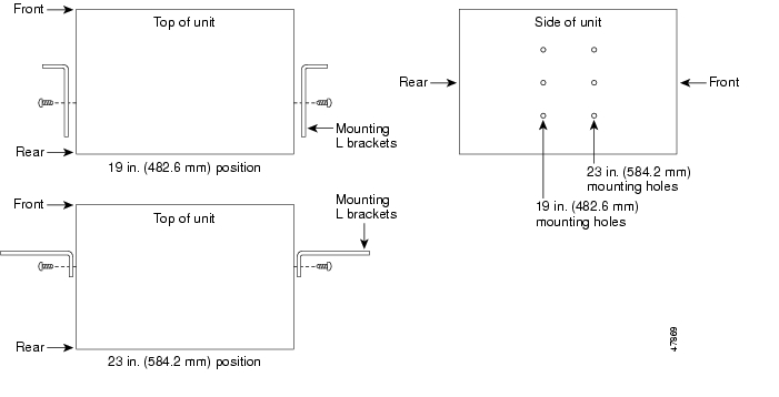
The shelf assembly comes preset for installation in a 23-inch rack, but you can reverse the mounting bracket to fit the smaller, 19-inch rack. The following steps describe how to reverse the shelf assembly mounting bracket to fit a 19-inch rack.
Procedure: Reverse the Mounting Bracket to Fit a 19-Inch Rack
Step 1
Step 2
Text imprinted on the mounting bracket will now also be upside down.
Step 3
The narrow side of the mounting bracket should be towards the front of the shelf assembly. Text imprinted on the mounting bracket should be visible and upside down.
Step 4
Step 5
Step 6
Figure 1-2 Reversing the mounting brackets (23-inch position to 19-inch position)
1.3.2 Mounting a Single Node
Mounting the ONS 15454 in a rack requires a minimum of 18.5 inches of vertical rack space (and one inch for air flow). To ensure the mounting is secure, use two to four #12-24 mounting screws for each side of the shelf assembly. Figure 1-3 shows the rack mounting position for the ONS 15454.
Figure 1-3 Mounting an ONS 15454 in a rack
Two people should install the shelf assembly; however, one person can install it using the temporary set screws included. The shelf assembly should be empty for easier lifting. The front door can also be removed to lighten the shelf assembly (see the "Remove the Front Door" procedure).
Note
Procedure: Mount the Shelf Assembly in a Rack (One Person)
Step 1
Step 2
Step 3
Step 4
Step 5
Step 6
Note
Step 7
Procedure: Mount the Shelf Assembly in a Rack (Two People)
Step 1
Step 2
Step 3
Step 4
Step 5
Note
1.3.3 Mounting Multiple Nodes
Most standard seven-foot racks can hold four ONS 15454s and a fuse and alarm panel. However, unequal flange racks are limited to three ONS 15454s and a fuse and alarm panel or four ONS 15454s and a fuse and alarm panel from an adjacent rack.
If you are using the bottom brackets to install the fan-tray air filter, you can install three shelf assemblies in a standard seven-foot rack. If you are not using the bottom brackets, you can install four shelf assemblies in a rack. The advantage to using the bottom brackets is that you can replace the filter without removing the fan tray.
Procedure: Mount Multiple Shelf Assemblies in a Rack
Note
Step 1
Step 2
Step 3
1.3.3.1 Four Node Configuration
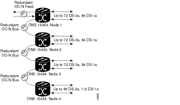
You can link multiple ONS 15454s using their OC-N cards (i.e., create a fiber-optic bus) to accommodate more access traffic than a single ONS 15454 can support. For example, if you need to drop more than 112 DS-1s or 96 DS-3s (the maximum that can be aggregated in a single node), you can link the nodes but not merge multiple nodes into a single ONS 15454. You can link nodes with OC-12 or OC-48 fiber spans as you would link any other two network nodes. The nodes can be co-located in a facility to aggregate more local traffic.
Figure 1-4 shows a four-shelf node setup. Each shelf assembly is reorganized as a separate node in the ONS 15454's software interface (Cisco Transport Controller [CTC]), and traffic is mapped using CTC cross-connect options. In the figure, each node uses redundant fiber-optic cards. Node 1 uses redundant OC-N transport and OC-N bus (connecting) cards for a total of four cards, with eight free slots remaining. Nodes 2 and 3 each use two redundant OC-N bus cards for a total of four cards, with eight free slots remaining. Node 4 uses redundant OC-12 bus cards for a total of two cards, with ten free slots remaining. The four node example presented here is one of many ways to set up a multiple-node configuration. See " Chapter 5, "SONET Topologies"" for more information about multiple-node configurations.
Figure 1-4 A four-shelf node configuration
1.3.3.2 ONS 15454 Bay Assembly
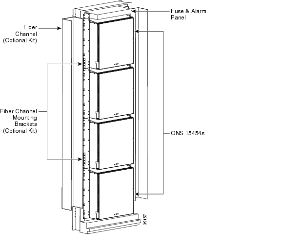
The Cisco ONS 15454 Bay Assembly simplifies ordering and installing the ONS 15454 because it allows you to order shelf assemblies pre-installed in a seven-foot rack. The Bay Assembly is available in a three- or four-shelf configuration. The three-shelf configuration includes three ONS 15454 shelf assemblies, a pre-wired fuse and alarm panel, and two cable-management trays. Optional fiber channels can be ordered. The four-shelf configuration includes four ONS 15454 shelf assemblies and a pre-wired fuse and alarm panel. Optional fiber channels can be ordered. A four shelf ONS 15454 Bay Assembly is shown in Figure 1-5.
Figure 1-5 A four-shelf ONS 15454 Bay Assembly
1.4 Front Door Access
The Critical, Major, and Minor alarm LEDs visible through the front door indicate whether a Critical, Major, or Minor alarm is present anywhere on the ONS 15454. These LEDs must be visible so technicians can quickly determine if any alarms are present. You can use the LCD to further isolate alarms. See Chapter 10, "Alarm Monitoring and Management" for more information.
This section tells you how to access ONS 15454 equipment in the front compartment. The ONS 15454 features a locked door to the front compartment. A pinned Allen key that unlocks the front door ships with the ONS 15454. A button on the right side of the shelf assembly releases the door. The front door provides access to the shelf assembly, cable-management tray, fan-tray assembly, and LCD screen ( Figure 1-8).
You can remove the front door of the ONS 15454 to provide unrestricted access to the front of the shelf assembly. An erasable label ( Figure 1-6) is pasted on the inside of the front door. You can use the label to record slot assignments, port assignments, card types, node ID, rack ID, and serial number for the ONS 15454.
Figure 1-6 The front-door erasable label
Note
Figure 1-7 The laser warning on the front-door label
Procedure: Open the Front Cabinet Compartment (Door)
Note
Step 1
The ONS 15454 comes with a pinned hex key for locking and unlocking the front door. Turn the key counterclockwise to unlock the door and clockwise to lock it.
Step 2
Step 3
Figure 1-8 The ONS 15454 front door
Procedure: Remove the Front Door
Step 1
Step 2
Figure 1-9 Removing the ONS 15454 front door
1.5 Backplane Access
To access the ONS 15454 backplane, remove the two standard sheet metal covers on each side of the backplane ( Figure 1-10). Each sheet metal cover is held in place with nine 6-32 x 3/8 inch phillips screws.
Figure 1-10 Backplane sheet metal covers
Procedure: Remove the Backplane Sheet Metal Covers
Step 1
Step 2
Step 3
Step 4
1.5.1 Lower Backplane Cover
The lower section of the ONS 15454 backplane is covered by a clear plastic protector, which is held in place by five 6-32 x 1/2 inch screws. Remove the lower backplane cover to access the alarm interface panel (AIP), alarm pin field, frame ground, and power terminals.
Figure 1-11 Removing the lower backplane cover
Procedure: Remove the Lower Backplane Cover
Step 1
Step 2
Step 3
1.5.2 Alarm Interface Panel
The AIP is located above the alarm pin field on the lower section of the backplane. The AIP provides surge protection for the ONS 15454. It also provides an interface from the backplane to the fan-tray assembly and LCD. The AIP plugs into the backplane using a 96-pin DIN connector and is held in place with two retaining screws. The panel has a non-volatile memory chip that stores the unique node address (MAC address).
Note
The MAC address identifies the nodes that support circuits. It allows CTC to determine circuit sources, destinations, and spans. The Timing Communication and Control+ (TCC+) cards in the ONS 15454 also read the MAC address to store the node database. If the AIP fails, a MAC Fail alarm displays on the CTC Alarms menu and/or the LCD display on the fan tray will go blank.
Note
1.6 EIA Installation
Optional EIA backplane covers are typically pre-installed when ordered with the ONS 15454. EIAs must be ordered when using DS-1, DS-3, DS3XM-6, or EC-1 cards. A minimum amount of assembly may be required when EIAs are ordered separately from the ONS 15454. Four different EIA backplane covers are available for the ONS 15454: BNC, High-Density BNC, SMB, and AMP Champ. This section describes each EIA in detail.
EIAs are attached to the shelf assembly backplane to provide coaxial cable connections. EIAs are available with SMB and BNC connectors for DS-3 or EC-1 cards. EIAs are available with AMP Champ connectors for DS-1 cards. You must use SMB EIAs for DS-1 twisted-pair cable installation. You can install EIAs on one or both sides of the ONS 15454 backplane in any combination (in other words, AMP Champ on Side A and BNC on Side B or High-Density BNC on side A and SMB on side B, and so forth).
If you are installing EIAs after the shelf assembly is installed, plug the EIA into the backplane. The EIA has six electrical connectors that plug into six corresponding backplane connectors. The EIA backplane must replace the standard sheet metal cover to provide access to the coaxial cable connectors. The EIA sheet metal covers use the same screw holes as the solid backplane panels, but they have 12 additional 6-32 x 1/2 inch phillips screw holes so you can screw down the cover and the board using standoffs on the EIA board. This section describes each EIA and provides installation procedures.
For EIA replacement procedures, refer to the Cisco ONS 15454 Troubleshooting and Maintenance Guide. For information about attaching ferrites to EIA connectors, see the "Ferrite Installation" section.
1.6.1 BNC EIA
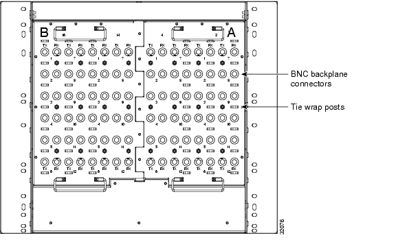
The ONS 15454 BNC EIA supports 24 DS-3 circuits on each side of the ONS 15454 (24 transmit and 24 receive connectors). If you install BNC EIAs on both sides of the shelf assembly, the ONS 15454 hosts up to 48 circuits. The BNC connectors on the EIA supports Trompeter UCBJ224 (75 Ohm) 4 leg connectors (King or ITT are also compatible). You can use BNC EIAs for DS-3 (including the DS3XM-6) or EC-1 cards. Figure 1-39 shows the ONS 15454 with pre-installed BNC EIAs.
To install coaxial cable with BNC connectors, see the "BNC Connector Installation" section.
Figure 1-12 A BNC backplane for use in 1:1 protection schemes
The EIA side marked "A" has 24 pairs of BNC connectors. The first 12 pairs of BNC connectors correspond to Ports 1 - 12 for a 12-port card and map to Slot 2 on the shelf assembly. The BNC connector pairs are marked "Tx" and "Rx" to indicate transmit and receive cables for each port. You can install an additional card in Slot 1 as a protect card for the card in Slot 2. The second 12 BNC connector pairs correspond to Ports 1 - 12 for a 12-port card and map to Slot 4 on the shelf assembly. You can install an additional card in Slot 3 as a protect card for the card in Slot 4. Slots 5 and 6 do not support DS-3 cards when BNC connectors are used.
The EIA side marked "B" provides an additional 24 pairs of BNC connectors. The first 12 BNC connector pairs correspond to Ports 1 - 12 for a 12-port card and map to Slot 14 on the shelf assembly. The BNC connector pairs are marked "Tx" and "Rx" to indicate transmit and receive cables for each port. You can install an additional card in Slot 15 as a protect card for the card in Slot 14. The second 12 BNC connector pairs correspond to Ports 1 - 12 for a 12-port card and map to Slot 16 on the shelf assembly. You can install an additional card in Slot 17 as a protect card for the card in Slot 16. Slots 12 and 13 do not support DS-3 cards when BNC connectors are used.
When BNC connectors are used with a DS3N-12 card in Slot 3 or 15, the 1:N card protection extends only to the two slots adjacent to the 1:N card due to BNC wiring constraints.
1.6.2 High-Density BNC EIA
The ONS 15454 High-Density BNC EIA supports 48 DS-3 circuits on each side of the ONS 15454 (48 transmit and 48 receive connectors). If you install BNC EIAs on both sides of the unit, the ONS 15454 hosts up to 96 circuits. The High-Density BNC EIA supports Trompeter UCBJ224 (75 Ohm) 4 leg connectors (King or ITT are also compatible). You can use High-Density BNC EIAs for DS-3 (including the DS3XM-6) or EC-1 cards. Figure 1-13 shows the ONS 15454 with pre-installed High-Density BNC EIAs.
To install coaxial cable with High-Density BNC connectors, see the "High-Density BNC Connector Installation" section.
Figure 1-13 A High-Density BNC backplane for use in 1:N protection schemes
The EIA side marked "A" hosts 48 pairs of BNC connectors. Each column of connector pairs is numbered and corresponds to the slot of the same number. The first column (12 pairs) of BNC connectors corresponds to Slot 1 on the shelf assembly, the second column to Slot 2, the third column to Slot 4, and the fourth column to Slot 5. The rows of connectors correspond to Ports 1 - 12 of a 12-port card.
The EIA side marked "B" provides an additional 48 pairs of BNC connectors. The first column (12 pairs) of BNC connectors corresponds to Slot 13 on the shelf assembly, the second column to Slot 14, the third column to Slot 16, and the fourth column to Slot 17. The rows of connectors correspond to Ports 1 - 12 of a 12-port card. The BNC connector pairs are marked "Tx" and "Rx" to indicate transmit and receive cables for each port. The High-Density BNC EIA supports both 1:1 and 1:N protection across all slots.
1.6.3 SMB EIA
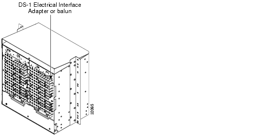
The ONS 15454 SMB EIA supports AMP 415484-1 75 Ohm 4 leg connectors. You can use SMB EIAs with DS-1, DS-3 (including the DS3XM-6), and EC-1 cards. If you use DS-1 cards, use the DS-1 electrical interface adapter to terminate the twisted pair DS-1 cable from the backplane.
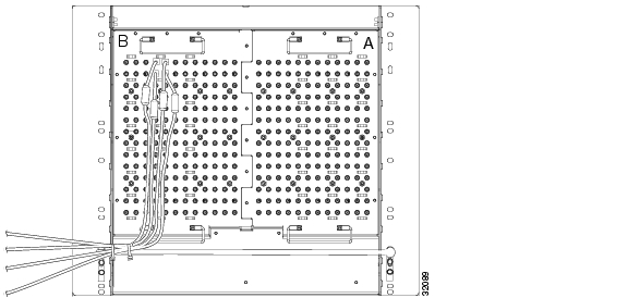
Figure 1-14 shows the ONS 15454 with pre-installed SMB EIAs and the sheet metal cover and screw locations for the EIA.To install SMB connectors, see the "SMB Connector Installation" section.
Figure 1-14 An SMB EIA backplane
The SMB EIA has 84 transmit and 84 receive connectors on each side of the ONS 15454 for a total of 168 SMB connectors (84 circuits).
The EIA side marked "A" hosts 84 SMB connectors in six columns of 14 connectors. The "A" side columns are numbered 1 - 6 and correspond to Slots 1 - 6 on the shelf assembly. The EIA side marked "B" hosts an additional 84 SMB connectors in six columns of 14 connectors. The "B" side columns are numbered 12 - 17 and correspond to Slots 12 - 17 on the shelf assembly. The connector rows are numbered 1 - 14 and correspond to the 14 ports on a DS-1 card.
For DS-3 or EC-1, the EIA supports 72 transmit and 72 receive connectors, for a total of 144 SMB connectors (72 circuits). If you use a DS-3 or EC-1 card, only Ports 1 - 12 are active. If you use a DS3XM-6 card, only Ports 1 - 6 are active. The SMB connector pairs are marked "Tx" and "Rx" to identify transmit and receive cables for each port. If you use SMB connectors, you can install DS-1, DS-3, or EC-1 cards in any multispeed slot.
1.6.4 AMP Champ EIA
The ONS 15454 AMP Champ EIA supports 64-pin (32 pair) AMP Champ connectors for each slot on both sides of the shelf assembly where the EIA is installed. Cisco AMP Champ connectors are female AMP # 552246-1 with AMP # 552562-2 bail locks. Each AMP Champ connector supports 14 DS-1 ports. You can use AMP Champ EIAs with DS-1 cards only. Figure 1-15 shows the ONS 15454 with pre-installed AMP Champ EIAs and the corresponding sheet metal cover and screw locations for the EIA.
To install AMP Champ connector DS-1 cables, see the "AMP Champ Connector Installation" section.
For information about attaching ferrites to AMP Champ connectors, see the "Ferrite Installation" section.
For information about AMP champ cable management, see the "AMP Champ Cable Management" section.
Figure 1-15 An AMP EIA Champ backplane
The EIA side marked "A" hosts six AMP Champ connectors. The connectors are numbered 1 - 6 for the corresponding slots on the shelf assembly. Each AMP Champ connector on the backplane supports 14 DS-1 ports for a DS1-14 card, and each connector features 28 live pairs—one transmit pair and one receive pair—for each DS-1 port.
The EIA side marked "B" hosts six AMP Champ connectors. The connectors are labeled 12-17 for the corresponding slots on the shelf assembly. Each AMP Champ connector on the backplane supports 14 DS-1 ports for a DS1-14 card, and each connector features 28 live pairs—one transmit pair and one receive pair—for each DS-1 port.
Note
Caution
Procedure: Install a BNC, High-Density BNC, or SMB EIA
See the "Install the AMP Champ EIA" procedure if you are using an AMP Champ EIA.
Step 1
Step 2
Step 3
Step 4
Step 5
Step 6
If you are using SMB EIAs to make DS-1 connections, you need the DS-1 electrical interface adapter, commonly referred to as a balun (P/N 15454-WW-14=).
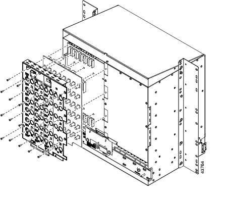
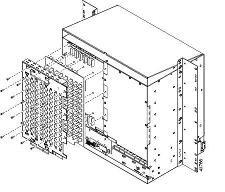
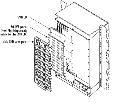
Figure 1-16 shows a BNC EIA installation. Figure 1-17 shows High-Density BNC EIA installation. Figure 1-18 shows an SMB EIA installation.
Figure 1-16 Installing the BNC EIA
Figure 1-17 Installing the High-Density BNC EIA
Figure 1-18 Installing the SMB EIA (use a balun for DS-1 connections)
Procedure: Install the AMP Champ EIA
Step 1
Step 2
Step 3
Step 4
Step 5
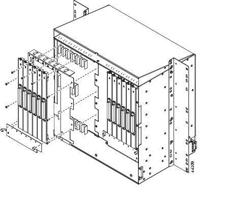
Figure 1-19 shows an AMP Champ EIA installation.
Figure 1-19 Installing the AMP CHAMP EIA
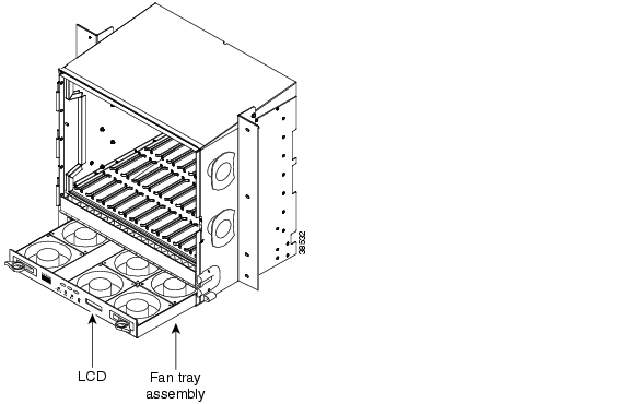
1.7 Fan-Tray Assembly Installation
The fan-tray assembly is located at the bottom of the ONS 15454 front compartment. The fan tray is a removable drawer that holds fans and fan-control circuitry for the ONS 15454. The front door can be left in place when removing or installing the fan tray but removal is recommended. After you install the fan tray, you should only need to access it if a fan failure occurs or you need to replace or clean the fan-tray air filter.
The front of the fan-tray assembly has an LCD screen that provides slot and port-level information for all ONS 15454 card slots, including the number of Critical, Major, and Minor alarms.
The fan-tray assembly features an air filter at the bottom of the tray that you can install and remove by hand. Remove and visually inspect this filter every 30 days and keep spare filters in stock. See the Cisco ONS 15454 Troubleshooting and Maintenance Guide for information about cleaning and maintaining the fan-tray air filter.
Note
Caution
Caution
Note
If one or more fans fail on the fan-tray assembly, replace the entire assembly. You cannot replace individual fans. The red Fan Fail LED on the front of the fan tray illuminates when one or more fans fail. For fan tray replacement instructions, see the "Install the Fan-Tray Assembly" procedure. The red Fan Fail LED clears after you install a working fan tray.
Fan speed is controlled by TCC+ card temperature sensors. The sensors measure the input air temperature at the fan-tray assembly. Fan speed options are low, medium, and high. If the TCC+ card fails, the fans automatically shift to high speed. The temperature measured by the TCC+ sensors is displayed on the LCD screen.
Procedure: Install the Bottom Brackets and Air Filter
The shelf assembly ships with bottom brackets that you should use to install the air filter. The bottom brackets consist of two grooved metal pieces that attach to the bottom of the shelf assembly using three screws each. When you use the bottom bracket to install the fan-tray air filter, you do not need to remove the fan-tray assembly to access the air filter. Attach the brackets to the bottom of the shelf assembly before installing the rack.
Although the filter will work if it is installed with either side facing up, Cisco recommends that you install it with the metal bracing facing up to preserve the surface of the filter.
Note
Step 1
Step 2
Step 3
Each bracket has a filter stopper and a flange on one end. Make sure to attach the brackets with the stoppers and flanges facing the rear of the shelf assembly (the top, if the ONS 15454 is face-down during installation).
Figure 1-20 illustrates bottom bracket installation. If you do not use the bottom brackets, in the future you must remove the fan-tray assembly before removing the air filter. The bottom brackets enable you to clean and replace the air filter without removing the fan-tray assembly.
Figure 1-20 Installing the bottom brackets
If you are using the bottom brackets to install the fan-tray air filter, you can install three shelf assemblies in a standard seven-foot rack. If you are not using the bottom brackets, you can install four shelf assemblies in a rack.
Step 4
Procedure: Install the Fan-Tray Assembly
To install the fan-tray assembly, it is not necessary to move any of the cable-management facilities.
Caution
Caution
Step 1
Step 2
Step 3
Figure 1-21 shows the location of the fan tray.
Figure 1-21 Installing the fan-tray assembly
1.8 Power and Ground Installation
This section explains how to connect the ONS 15454 assembly to the power supply. Ground the equipment according to Telcordia standards or local practices.
Warning
Warning
Caution
Warning
Warning
Warning
Warning
Cisco recommends the following wiring conventions, but customer conventions prevail:
•
•
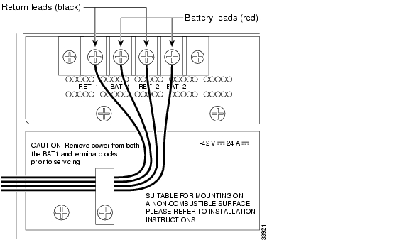
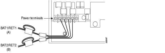
The ONS 15454 has redundant -48V DC #8 power terminals on the shelf assembly backplane. The terminals are labeled BAT1, RET1, BAT2, and RET2 and are located on the lower section of the backplane behind a clear plastic cover. See the "Lower Backplane Cover" section for information about accessing the power terminals.
To install redundant power feeds, use four power cables and one ground cable. For a single power feed, only two power cables (#10 AWG, copper conductor, 194ΑF [90ΑC]) and one ground cable (#6 AWG) are required. Use a conductor with low impedance to ensure circuit overcurrent protection. However, the conductor must have the capability to safely conduct any fault current that might be imposed.
The existing ground post is a #10-32 bolt. The nut provided for a field connection is also a #10, with an integral lock washer. The lug must be a dual-hole type and rated to accept the #6 AWG cable. Two posts are provided on the Cisco ONS 15454 to accommodate the dual-hole lug. Figure 1-22 shows the location of the ground posts.
Figure 1-22 Ground posts on the ONS 15454 backplane
For information about attaching ferrites to power cabling, see the "Ferrite Installation" section.
Warning
Warning
Procedure: Install Redundant Power Feeds
Ground only one cable to ground the shelf assembly. Terminate the other end of the ground cable to ground according to local site practice. The ONS 15454 backplane also has a ground terminal on the right side of the backplane. Connect a ground terminal for the frame ground (FGND) terminal according to local site practice.
If the system loses power or both TCC+ cards are reset, you must reset the ONS 15454 clock. After powering down, the date defaults to January 1, 1970, 00:04:15. To reset the clock, see the "Setting Up Basic Node Information" section on page 3-2.
Note
Warning
Step 1
Step 2
Warning
Figure 1-23 Power terminals
Step 3
Note
Caution
Caution
Step 4
Note
Step 5
Warning
Step 6
Step 7
Route the cables out below the power terminals using the plastic cable clamp.
1.9 Alarm, Timing, LAN, and Craft Pin Connections
Caution
The ONS 15454 has a backplane pin field located at the bottom of the backplane. The backplane pin field provides 0.045 square inch wire-wrap pins for enabling external alarms, timing input and output, and craft interface terminals. This section describes the backplane pin field and the pin assignments for the field. Figure 1-24 shows the wire-wrap pins on the backplane pin field. Beneath each wire-wrap pin is a frame ground pin. Frame ground pins are labeled FG1, FG2, FG3, etc. Install the ground shield of the cables connected to the backplane to the ground pin that corresponds to the pin field used. Figure 1-24 shows pinouts for the ONS 15454.
Figure 1-24 Pinouts
Note
1.9.1 Alarm Installation
The alarm pin field supports up to 17 alarm contacts, including four audible alarms, four visual alarms, one alarm cutoff (ACO), and four user-definable alarm input and output contacts.
Audible alarm contacts are in the LOCAL ALARM AUD pin field and visual contacts are in the LOCAL ALARM VIS pin field. Both of these alarms are in the LOCAL ALARMS category. User-definable contacts are in the ENVIR ALARM IN and ENVIR ALARM OUT pin fields. These alarms are in the ENVIR ALARMS category; you must have the AIC card installed to use the ENVIR ALARMS. Alarm contacts are Normally Open (N/O), meaning that the system closes the alarm contacts when the corresponding alarm conditions are present. Each alarm contact consists of two wire-wrap pins on the shelf assembly backplane. Visual and audible alarm contacts are classified as Critical, Major, Minor, and Remote. Figure 1-24 shows alarm pin assignments.
Visual and audible alarms are typically wired to trigger an alarm light at a central alarm collection point when the corresponding contacts are closed. You can use the Alarm Cutoff pins to activate a remote ACO for audible alarms. You can also activate the ACO function by pressing the ACO button on the TCC+ card faceplate. The ACO function clears all audible alarm indications. After clearing the audible alarm indication, the alarm is still present and viewable in the Alarms tab in CTC.
Procedure: Install Alarm Wires on the Backplane
Step 1
Step 2
Note
1.9.2 Timing Installation
The ONS 15454 backplane supports two Building Integrated Timing Supply (BITS) clock pin fields. The first four BITS pins, rows 3 and 4, support output and input from the first external timing device. The last four BITS pins, rows 1 and 2, perform the identical functions for the second external timing device. Table 1-2 lists the pin assignments for the BITS timing pin fields.
Note
Procedure: Install Timing Wires on the Backplane
Step 1
Step 2
Step 3
Note
1.9.3 LAN Installation
Use the LAN pins on the ONS 15454 backplane to connect the ONS 15454 to a workstation or Ethernet LAN, or to a LAN modem for remote access to the node. You can also use the LAN port on the TCC+ faceplate to connect a workstation or to connect the ONS 15454 to the network. Table 1-3 shows the LAN pin assignments.
Before you can connect an ONS 15454 to other ONS 15454s or to a LAN, you must change the default IP address that is shipped with each ONS 15454 (192.1.0.2). See the "Change IP Address, Default Router, and Network Mask Using the LCD" procedure on page 3-4.
*The Cisco ONS 15454 is DCE.
Procedure: Install LAN Wires on the Backplane
Step 1
Step 2
Step 3
1.9.4 TL1 Craft Interface Installation
You can use the craft pins on the ONS 15454 backplane or the RS-232 port on the TCC+ faceplate to create a VT100 emulation window to serve as a TL1 craft interface to the ONS 15454. Use a straight-through cable to connect to the RS-232 port. Table 1-4 shows the pin assignments for the CRAFT pin field.
Note
Table 1-4 Craft Interface Pin Assignments
Craft
A1
Receive
A2
Transmit
A3
Ground
A4
DTR
Procedure: Install Craft Interface Wires on the Backplane
Step 1
Step 2
Note
Step 3
Step 4
1.10 Coaxial Cable Installation
Caution
When using ONS 15454 DS-3 electrical cables, the cables must terminate on an EIA installed on the ONS 15454 backplane. EIAs are available with SMB and BNC connectors. All DS-3 cables connected to the ONS 15454 DS-3 card must terminate with coaxial cables using the desired connector type to connect to the specified EIA. For information about physically installing an EIA in the field, see the "Install a BNC, High-Density BNC, or SMB EIA" procedure. For information about coaxial cable management, see the "Coaxial Cable Management" section.
The electromagnetic compatibility (EMC) performance of the system depends on good-quality DS-3 coaxial cables, such as Shuner Type G 03233 D, or the equivalent.
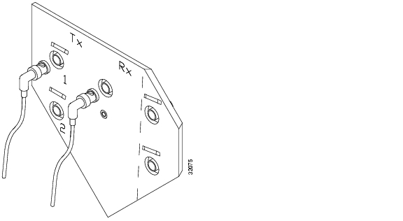
1.10.1 BNC Connector Installation
For a description of BNC EIAs, see the "BNC EIA" section. The BNC connectors on the EIA supports Trompeter UCBJ224 (75 Ohm) 4 leg connectors. Right-angle mating connectors for the connecting cable are AMP 413588-2 (75 Ohm) connectors. If preferred, you can also use a straight connector of the same type. Use RG-59/U cable to connect to the ONS 15454 BNC EIA. These cables are recommended to connect to a patch panel and are designed for long runs of up to 450 feet.
Procedure: Install Coaxial Cable With BNC Connectors
Step 1
Figure 1-25 shows how to connect a coaxial cable to the BNC EIA using a right-angle BNC cable connector.
Step 2
Step 3
Step 4
Step 5
Step 6
Figure 1-25 Using a right-angle connector to install coaxial cable with BNC connectors
Note
Step 7
1.10.2 High-Density BNC Connector Installation
The High-Density BNC EIA supports Trompeter UCBJ224 (75 Ohm) 4 leg connectors. Use straight connectors on RG-59/U cable to connect to the High-Density BNC EIA. Cisco recommends these cables for connection to a patch panel; they are designed for long runs of up to 450 feet. For more detail, see the "High-Density BNC EIA" section.
Although not required, Cisco strongly recommends using the BNC insertion tool to connect cables to the EIA. Refer to the Cisco ONS 15454 Troubleshooting and Maintenance Guide for more information about the insertion tool.
Procedure: Install Coaxial Cable With High-Density BNC Connectors
Step 1
Step 2
Step 3
Step 4
Step 5
Step 6
The rubber coated edges of the side cutouts prevent the cables from chafing.
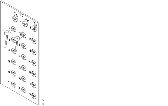
1.10.3 SMB Connector Installation
The SMB backplane cover is similar to the BNC cover. For further detail, see the "SMB EIA" section. The SMB connectors on the EIA are AMP 415504-3 (75 Ohm) 4 leg connectors. Right-angle mating connectors for the connecting cable are AMP 415484-2 (75 Ohm) connectors. Use RG-179/U cable to connect to the ONS 15454 EIA. Cisco recommends these cables for connection to a patch panel; they are not designed for long runs (over 50 feet). Range does not affect loopback testing.
For information about attaching ferrites to SMB/BNC connectors, see the "Ferrite Installation" section.
Procedure: Install Coaxial Cable with SMB Connectors
Refer to Figure 1-26 when performing the following steps.
Step 1
Step 2
Step 3
Step 4
Figure 1-26 Installing coaxial cable with SMB connectors
Warning
Step 5
1.11 DS-1 Cable Installation
DS-1s support both twisted pair wire-wrap cabling and AMP Champ connector cabling. Install the proper backplane EIA on the ONS 15454 for each cabling option. This section provides information about the DS-1 EIA options.
For information about DS-1 cable management, see the "DS-1 Twisted-Pair Cable Management" section.
1.11.1 Twisted Pair Wire-Wrap Installation
Installing twisted-pair, wire-wrap DS-1 cables requires separate pairs of grounded twisted-pair cables for receive (in) and transmit (out). Prepare four cables, two for receive and two for transmit, for each DS-1 facility to be installed.
Caution
If you use DS-1 electrical twisted-pair cables, equip the ONS 15454 with an SMB EIA on each side of the backplane where DS-1 cables will terminate. You must install special DS-1 electrical interface adapters, commonly referred to as a balun, on every transmit and receive connector for each DS-1 termination.
Note
If you install DS-1 cards in the ONS 15454, you must fit the corresponding transmit and receive SMB connectors on the EIA with a DS-1 electrical interface adapter. You can install the adapter on the SMB connector for the port. The adaptor has wire-wrap posts for DS-1 transmit and receive cables. Figure 1-27 shows the DS-1 electrical interface adapter.
Figure 1-27 DS-1 electrical interface adapter (balun)
Each DS-1 electrical interface adapter has a female SMB connector on one end and a pair of .045 inch square wire-wrap posts on the other end. The wire-wrap posts are .200 inches apart.
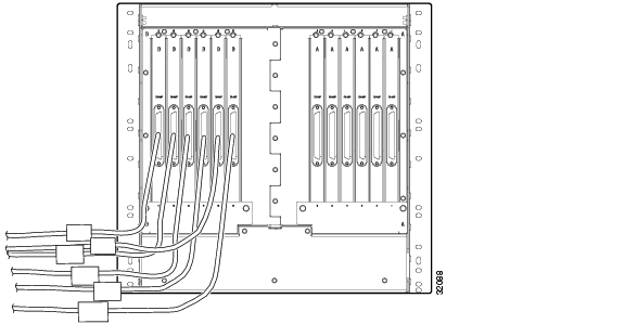
Procedure: Install DS-1 Cables Using Electrical Interface Adapters (Balun)
All DS-1 cables connected to the ONS 15454 DS-1 ports must terminate with twisted-pair cables to connect to the DS-1 electrical interface adapter. The DS-1 electrical interface adapters project 1.72 inches beyond the SMB EIA.
Step 1
Step 2
Step 3
a.
b.
c.
If you put DS1N-14 cards in Slots 3 and 15 to form 1:N protection groups, do not wire Slots 3 and 15 for DS-1 electrical interface adapters.
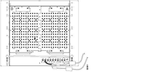
Figure 1-28 shows a ONS 15454 backplane with an SMB EIA with DS-1 electrical interface adapters attached on both sides of the shelf assembly to create DS-1 twisted-pair termination points.
Figure 1-28 A backplane with SMB EIA for DS-1 cables
1.11.2 AMP Champ Connector Installation
To install AMP Champ connector DS-1 cables, you must use 64-pin bundled cable connectors with a 64-pin male AMP Champ connector. You need an AMP Champ connector #552276-1 for the receptacle side and #1-552496-1 (for cable diameter .475in.-.540in) or #2-552496-1 (for cable diameter .540in.-.605in.) for the right-angle shell housing (or their functional equivalent). The corresponding 64-pin female AMP Champ connector on the AMP Champ EIA supports one receive and one transmit for each DS-1 port for the corresponding card slot.
Because each DS1-14 card supports 14 DS-1 ports, only 56 pins (28 pairs) of the 64-pin connector are used. Prepare one 56-wire cable for each DS-1 facility installed. Table 1-5 shows the pin assignments for the AMP Champ connectors on the ONS 15454 AMP Champ EIA. See the "AMP Champ EIA" section for more information about the AMP Champ EIA.
Table 1-6 shows the pin assignments for the AMP Champ connectors on the ONS 15454 AMP Champ EIA for a shielded DS1 cable.
Caution
When using DS-1 AMP Champ cables, you must equip the ONS 15454 with an AMP Champ connector EIA on each side of the backplane where DS-1 cables will terminate. Each AMP Champ connector on the EIA corresponds to a slot in the shelf assembly and is numbered accordingly. The AMP Champ connectors have screw-down tooling at each end of the connector. To install an AMP Champ backplane cover, see the "AMP Champ EIA" section.
Procedure: Install DS-1 AMP Champ Cables on the AMP Champ EIA
Step 1
Step 2
Step 3
The female connector has grooves on the outside edge for snapping the clips into place.
Note
1.12 Card Installation
This section describes the how to install ONS 15454 cards. The procedure for installing ONS 15454 cards is nearly identical for each card. AIC card installation is slightly different from all other cards and is described in its own procedure. The XC/XCVT /XC10G and TCC+ installation procedures are virtually identical and are described in one procedure. Installation for all other cards is the same and is covered by one procedure.
The order in which you install cards is important. The proper sequence follows:
1.
2.
3.
4.
5.
6.
Note
Note
ONS 15454 cards have electrical plugs at the back that plug into electrical connectors on the shelf assembly backplane. When the ejectors are fully closed, the card plugs into the assembly backplane. Figure 1-29 shows card installation.
Warning
Caution
Warning
Warning
Warning
Figure 1-29 Installing cards in the ONS 15454
1.12.1 Slot Requirements
The ONS 15454 shelf assembly has 17 card slots numbered sequentially from left to right. Slots 1 - 4 and 14 - 17 are multispeed slots. They can host any ONS 15454 card, except the OC48IR 1310, OC48LR 1550, OC48ELR 1550, and OC192LR 1550 cards. Slots 5, 6, 12 and 13 are high-speed slots. They can host any ONS 15454 card, including the OC48IR 1310, OC48LR 1550, OC48ELR 1550, and OC192LR 1550 cards. You can install the OC48 IR/STM16 SH AS 1310 and the OC48 LR/STM16 LH AS 1550 cards in any multispeed or high-speed card slot.
Slots 7 and 11 are dedicated to TCC+ cards. Slots 8 and 10 are dedicated to cross-connect (XC, XCVT, XC10G) cards. Slot 9 is reserved for the optional Alarm Interface Controller (AIC) card. Slots 3 and 15 can also host DS1N-14 and DS3N-12 cards that are used in 1:N protection.
Caution
Shelf assembly slots have symbols indicating the type of cards that you can install in them. Each ONS 15454 card has a corresponding symbol. The symbol on the card must match the symbol on the slot.
Table 1-7 shows the slot and card symbol definitions.
Table 1-8 lists the number of ports, line rates, connector options, and connector locations for ONS 15454 optical and electrical cards.
* When used as a protect card, the card does not have a physical external connection. The protect card connects to the working card(s) through the backplane and becomes active when the working card fails. The protect card then uses the physical connection of the failed card.
Procedure: Install the TCC+ and XC/XCVT/XC10G Cards
Although the installation procedure is the same for both TCC+ and XC/XCVT/XC10G cards, you must install the TCC+ card and let it initialize before installing the XC/XCVT/XC10G cards. The TCC+ card houses the ONS 15454 software. For a detailed explanation, see Chapter 2, "Software Installation."
Note
Step 1
Step 2
Step 3
Step 4
Step 5
Note
Step 6
Tip
Procedure: Install Optical, Electrical, and Ethernet Cards
Although the installation procedure is the same for optical, electrical, and Ethernet cards, you must install the optical cards before installing the electrical cards.
Warning
Step 1
Step 2
Step 3
Step 4
Step 5
Step 6
Step 7
Procedure: Install the AIC Card
Step 1
Step 2
Step 3
Step 4
Step 5
Step 6
Step 7
Step 8
1.12.2 Gigabit Interface Converter
GBICs are hot-swappable input/output devices that plug into a Gigabit Ethernet (E1000-2 or E1000-2-G) card to link the card with the fiber-optic network. Cisco provides two GBIC models: one for short reach applications (part number 15454-GBIC-SX) and one for long-reach applications (15454-GBIC-LX). The short reach, or "SX" model, connects to multimode fiber and the long reach, or "LX" model, requires single-mode fiber. Because the GBICs are very similar in appearance, check the label on the GBIC carefully before installing it.
Note
For a description of GBICs and their capabilities, see Chapter 9, "Ethernet Operation."
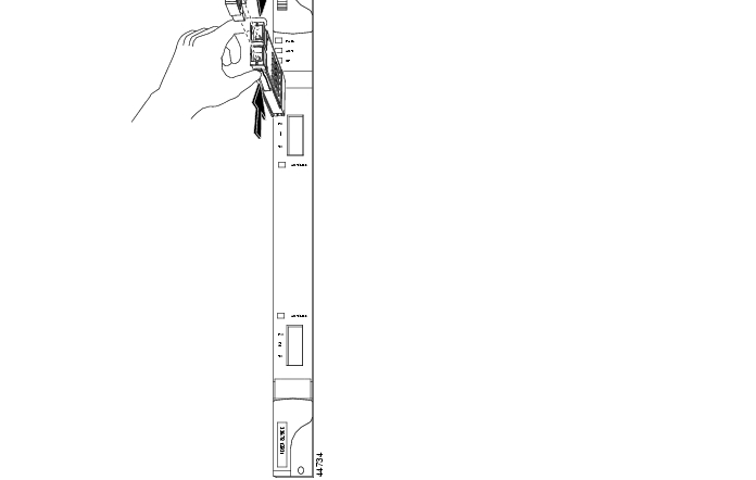
Procedure: Install Gigabit Interface Converters
Step 1
Step 2
Step 3
GBICs are hot-swappable and can therefore be installed/removed while the card/shelf assembly is powered and running.
Note
Figure 1-30 Installing a GBIC on an E1000-2 card
Step 4
The click indicates the GBIC is locked into the slot.
Warning
Warning
Step 5
Step 6
Procedure: Remove a Gigabit Interface Converter
Step 1
Step 2
Step 3
A flap closes over the GBIC slot to protect the connector on the Gigabit Ethernet card.
1.13 Fiber-Optic Cable Installation
This section explains how to install optical fibers on OC-N cards.
Caution
ONS OC-N cards feature SC connectors. To install fiber-optic cables in the ONS 15454, a fiber cable with the corresponding connector type must be connected to the transmit and receive ports on the ONS 15454 cards. On ONS 15454 optical card ports, the top connector is transmit and the bottom connector is receive. Cisco recommends that the transmit and receive and the working and protection fibers be labeled at each end of the fiber span to avoid confusion with cables that are similar in appearance.
For information about fiber cable management, see the "Optical Cable Management" section.
Warning
Warning
Warning
Warning
Caution
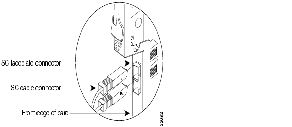
Procedure: Install Fiber-Optic Cables on OC-N Cards
Note
Step 1
Figure 1-31 Installing fiber-optic cables
Step 2
Step 3
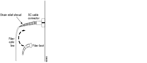
Procedure: Install the Fiber Boot
Cisco provides clear plastic fiber boots for the OC-3, OC-12, and OC-48 (except OC48 AS) cards. The boots prevent hanging fibers from bending too sharply, which may degrade performance. The boots also prevent the front door from interfering with hanging fibers. The fiber boots are not necessary for the OC-192 and the OC-48 AS cards because of the angled SC connector. Figure 1-32 shows the fiber boot attachment.
You can install the fiber boots on the fiber-optic cables before or after the fibers are attached to the optic card.
Step 1
Step 2
Step 3
Slide the fiber boot forward along the fiber cable until the fiber boot fits snugly onto the end of the SC cable connector.
Figure 1-32 Attaching a fiber boot
1.14 Cable Routing and Management
The ONS 15454 cable management facilities include the following:
•
•
•
Note
•
•
•
•
Note
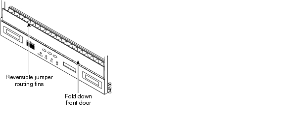
Figure 1-33 shows the cable management facilities that you can access through the fold-down front door, including the cable-routing channel and the jumper routing fins.
Figure 1-33 Managing cables on the front panel
1.14.1 Optical Cable Management
Optical cables connect to the SC connectors which are located on the faceplate of the optical cards and on GBICs. Route optical cables down through the fiber management clips on the optical card faceplate (shown in Figure 1-34) or, if the optical cables are connected to GBICs, route them down through the jumper routing fins (Ethernet cards do not have fiber management clips).
Route optical cables into the cable management area of the shelf assembly, through a cutout in the nearest side of the assembly, and onto the side of the assembly. A hinged panel on the front of the shelf assembly folds down to provide access to the cable-management tray.
Figure 1-34 Routing fiber-optic cables on the optical-card faceplate
Procedure: Route Fiber-Optic Cables in the Shelf Assembly
Step 1
Step 2
GBICs do not have fiber clips; therefore, if you are routing optical cable from an E1000-2-G or E1000-2 card, skip to Step 3.
Step 3
Step 4
Step 5
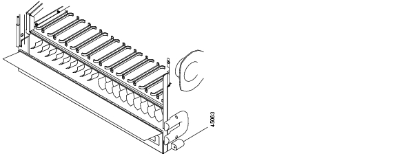
Figure 1-35 shows the fold-down front door of the shelf assembly open to display the cable routing channel.
Figure 1-35 Fold-down front door of the cable-management tray (displaying the cable routing channel)
1.14.2 Coaxial Cable Management
Coaxial cables connect to EIAs on the ONS 15454 backplane using cable connectors. EIAs feature cable-management eyelets for tie wrapping or lacing cables to the cover panel.
Procedure: Route the Coaxial Cables
Step 1
Note
Step 2
Step 3
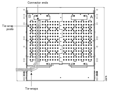
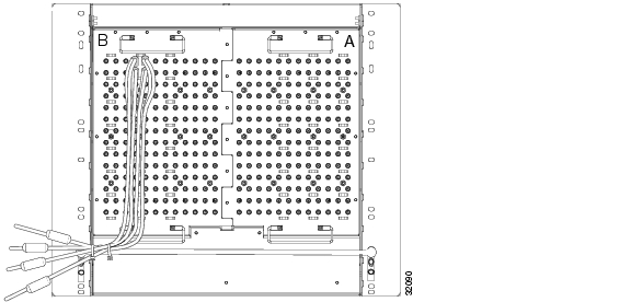
The shorter maximum distance available with the RG179 is due to a higher attenuation rate for the thinner cable. The attenuation rate for RG59 cable (based on testing with Belden 923, the equivalent of 328A cable) is ~1.0 dB/100 feet at 22 Mhz (DS-3 data rate). The attenuation rate of RG179 is
6.3 db/100 feet. Use a figure of 5.0 for total cable loss when making calculations. Figure 1-36 shows one side of the ONS 15454 backplane with SMB EIAs and the coaxial cables properly routed.Figure 1-36 Routing coaxial cable through the SMB EIA backplane
1.14.3 DS-1 Twisted-Pair Cable Management
Connect twisted pair/DS-1cables to SMB EIAs on the ONS 15454 backplane using cable connectors and DS-1 electrical interface adapters (balun).
Procedure: Route DS-1 Twisted-Pair Cables
When using DS-1 twisted-pair cables, the backplane cover has cutouts over the SMB cable connectors. SMB EIAs feature cable-management eyelets for tie wrapping or lacing cables to the cover panel.
Step 1
Step 2
Step 3
1.14.4 AMP Champ Cable Management
EIAs have cable management eyelets to tiewrap or lace cables to the cover panel. Tie wrap or lace the AMP Champ cables according to local site practice and route the cables. If you configure the ONS 15454 for a 23-inch rack, two additional inches of cable management area is available on each side of the shelf assembly. See the "AMP Champ EIA" section and the "AMP Champ Connector Installation" section and the for more information.
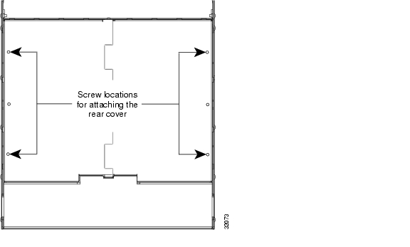
1.14.5 BIC Rear Cover Installation
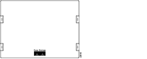
The ONS 15454 has an optional backplane interface connector (BIC) rear cover. This clear plastic cover provides additional protection for the cables and connectors on the backplane ( Figure 1-37). You can also install the optional spacers if more space is needed between the cables and rear cover ( Figure 1-38).
Figure 1-37 Clear BIC rear cover
Procedure: Install the BIC Rear Cover
Step 1
Only one pair of screws lines up with the screw slots on the mounting brackets, making them easy to locate.
Step 2
Step 3
Step 4
Step 5
Figure 1-38 Backplane attachment for BIC cover
Figure 1-39 Installing the BIC rear cover with spacers
1.15 Ferrite Installation
Place third-party ferrites on certain cables to dampen electromagnetic interference (EMI) from the ONS 15454. Ferrites must be added to meet the requirements of GR 1089. Refer to the ferrite manufacturer documentation for proper use and installation of the ferrites. The following illustrations show possible ferrite placements on the ONS 15454 for power cables, AMP Champ connectors, baluns, BNC/SMB connectors, and the wire-wrap pin field.
Procedure: Attach Ferrites to Power Cabling
Use a single oval ferrite TDK ZCAT2035-0930 for both pairs of cables and a block ferrite Fair Rite 0443164151 for each pair of cables.
Step 1
Step 2
Step 3
Figure 1-40 Attaching ferrites to power cabling
Figure 1-41 shows the suggested method for attaching the ferrites to AMP Champ connectors. Use a block ferrite Fair Rite 0443164151 for each cable.
Figure 1-41 Attaching ferrites to AMP Champ connectors
Figure 1-42 shows the suggested method for attaching ferrites to baluns. Use an oval ferrite TDK ZCAT 1730-0730 for each cable.
Figure 1-42 Attaching ferrites to electrical interface adapters (baluns)
Figure 1-43 shows the suggested method for attaching ferrites to SMB/BNC connectors. Use an oval ferrite TDK ZCAT1730-0730 for each cable and place the ferrite as close to the connector as possible.
Figure 1-43 Attaching ferrites to SMB/BNC connectors
Procedure: Attach Ferrites to Wire-Wrap Pin Fields
Use an oval ferrite TDK ZCAT1730-0730 and block ferrite Fair Rite 0443164151 for each pair of cables.
Figure 1-44 shows the suggested method for attaching ferrites to wire-wrap pin fields.
Step 1
Step 2
Figure 1-44 Attaching ferrites to wire-wrap pin fields
1.16 ONS 15454 Assembly Specifications
This section contains hardware and software specifications for the ONS 15454.
1.16.1 Bandwidth
•
•
•
1.16.2 Slot Assignments
•
•
•
•
•
•
1.16.3 Cards
•
•
•
•
•
•
•
•
•
•
•
•
•
•
•
•
•
•
•
•
•
•
•
•
•
•
•
•
Note
Note
1.16.4 Configurations
•
•
•
•
•
•
•
1.16.5 Cisco Transport Controller
•
•
•
1.16.6 External LAN Interface
•
•
1.16.7 TL1 Craft Interface
•
•
•
1.16.8 Modem Interface
•
•
1.16.9 Alarm Interface
•
•
•
•
1.16.10 EIA Interface
•
•
•
1.16.11 Nonvolatile Memory
64 MB, 3.0V FLASH memory
1.16.12 BITS Interface
•
•
•
1.16.13 System Timing
•
•
•
•
1.16.14 Power Specifications
•
•
•
•
1.16.15 Environmental Specifications
•
•
1.16.16 Dimensions
•
•
•
•
1.17 Installation Checklist
This section provides a summary of the steps required to install the ONS 15454. The section assumes that individual cards are used with their default provisioning values or will be provisioned by local technicians as required by the site.
1.18 ONS 15454 Software and Hardware Compatibility Matrix
Table 1-12 provides a matrix showing software and hardware compatibility for ONS 15454 Releases 2.0, 2.1, 2.2.0, 3.0. and 3.1.
If an upgrade is required for compatibility, call the Cisco Technical Assistance Center at 1-877-323-7368.
![]()
![]()
![]()
![]()
![]()
![]()
![]()
![]()
Posted: Fri Feb 22 16:56:18 PST 2008
All contents are Copyright © 1992--2008 Cisco Systems, Inc. All rights reserved.
Important Notices and Privacy Statement.