|
|

Table Of Contents
1.1 Network Troubleshooting Tests
1.2 Identify Points of Failure on a DS-N Circuit Path
1.2.1 Perform a Facility Loopback on a Source XTC Port
1.2.2 Perform a Hairpin on a Source Node XTC Port
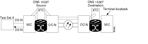
1.2.3 Perform a Terminal Loopback on a Destination XTC Port
1.2.4 Perform a Hairpin on a Destination Node XTC Port
1.2.5 Perform a Facility Loopback on a Destination XTC Card
1.3 Identify Points of Failure on an OC-N Circuit Path
1.3.1 Perform a Facility Loopback on a Source-Node OC-N Port
1.3.2 Perform a Cross-Connect Loopback on the Source OC-N Port
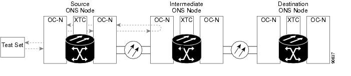
1.3.3 Perform a Terminal Loopback on a Source-Node OC-N Port
1.3.4 Perform a Facility Loopback on an Intermediate-Node OC-N Port
1.3.5 Perform a Terminal Loopback on an Intermediate-Node OC-N Port
1.3.6 Perform a Facility Loopback on a Destination-Node OC-N Port
1.3.7 Perform a Terminal Loopback on a Destination Node OC-N Port
1.4 Restoring the Database and Default Settings
1.4.1 Restore the Node Database
1.4.2 Restore the Node to Factory Configuration
1.5 PC Connectivity Troubleshooting
1.5.1 Unable to Verify the IP Configuration of Your PC
1.5.2 Browser Login Does Not Launch Java
1.5.3 Unable to Verify the NIC Connection on Your PC
1.5.4 Verify PC Connection to the ONS 15327 (Ping)
1.5.5 The IP Address of the Node is Unknown
1.6 CTC Operation Troubleshooting
1.6.1 Unable to Launch CTC Help After Removing Netscape
1.6.2 Unable to Change Node View to Network View
1.6.3 Browser Stalls When Downloading CTC JAR Files from XTC
1.6.5 Sluggish CTC Operation or Login Problems
1.6.6 Node Icon is Gray on CTC Network View
1.6.7 CTC Cannot Launch Due to Applet Security Restrictions
1.6.8 Java Runtime Environment Incompatible
1.6.9 Different CTC Releases Do Not Recognize Each Other
1.6.10 Username or Password Does Not Match the XTC Information
1.6.11 No IP Connectivity Exists Between Nodes
1.6.13 "Path in Use" Error When Creating a Circuit
1.6.14 Calculate and Design IP Subnets
1.6.16 VLAN Cannot Connect to Network Device from Untag Port
1.7.1 Circuit Transitions to Partial State
1.7.2 AIS-V on XTC-28-3 Unused VT Circuits
1.7.3 Circuit Creation Error with VT1.5 Circuit
1.7.4 DS3 Card Does Not Report AIS-P From External Equipment
1.7.5 OC-3 and DCC Limitations
1.7.6 ONS 15327 Switches Timing Reference
1.7.7 Holdover Synchronization Alarm
1.7.8 Free-Running Synchronization Mode
1.7.9 Daisy-Chained BITS Not Functioning
1.7.10 Blinking STAT LED after Installing a Card
1.8.1 Bit Errors Appear for a Traffic Card
1.8.2 Faulty Fiber-Optic Connections
1.9.2 Power Consumption for Node and Cards
General Troubleshooting
This chapter provides procedures for troubleshooting the most common problems encountered when operating a Cisco ONS 15327. To troubleshoot specific ONS 15327 alarms, see Chapter 2, "Alarm Troubleshooting." If you cannot find what you are looking for contact the Cisco Technical Assistance Center (Cisco TAC).
This chapter includes the following sections on network problems:
•
Network Troubleshooting Tests—Describes loopbacks and hairpin circuits, which you can use to test circuit paths through the network or logically isolate faults.
Note
•
•
The remaining sections describe symptoms, problems, and solutions that are categorized according to the following topics:
•
•
•
•
•
1.1 Network Troubleshooting Tests
Use loopbacks and hairpins to test newly created circuits before running live traffic or to logically locate the source of a network failure. All ONS 15327 line (traffic) cards, except Ethernet cards, allow loopbacks and hairpins.
Caution
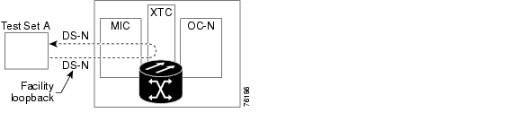
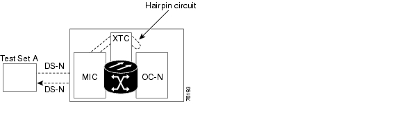
A facility loopback tests the line interface unit (LIU) of a card, the mechanical interface card (MIC), and related cabling. After applying a facility loopback on a port, use a test set to run traffic over the loopback. A successful facility loopback isolates the LIU, the MIC, or the cabling plant as the potential cause of a network problem. Figure 1-1 shows a facility loopback on an XTC-14 or XTC-28-3 card.
Figure 1-1 Facility Loopback Process on an XTC Card
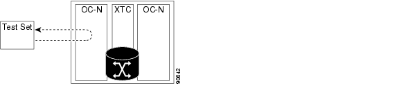
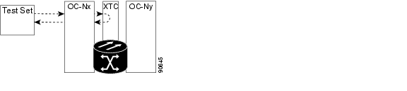
To test the LIU on an OC-N card, connect an optical test set to the OC-N port and perform a facility loopback or use a loopback or hairpin on a card that is farther along the circuit path. Figure 1-2 shows a facility loopback on an OC-N card.
Caution
Figure 1-2 Facility Loopback Process on an OC-N Card
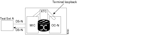
A terminal loopback tests a circuit path as it passes through the XTC card and loops back from the card with the loopback. Figure 1-3 shows a terminal loopback on an OC-N card. The test-set traffic comes in on the MIC card DS-N ports and goes through the XTC card to the OC-N card. The terminal loopback on the OC-N card turns the signal around before it reaches the LIU and sends it back through the XTC card to the MIC card. This test verifies that the XTC card cross-connect circuit paths are valid, but does not test the LIU on the OC-N card.
Figure 1-3 Terminal Loopback Process on an OC-N Card
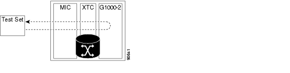
Figure 1-4 shows a terminal loopback on a G1000-2 card. The test-set traffic comes in on the MIC card DS-N ports and goes through the XTC card to the G1000-2 card. The terminal loopback on the G1000-2 card turns the signal around before it reaches the LIU and sends it back through the XTC card to the MIC card. This test verifies that the XTC card cross-connect circuit paths are valid, but does not test the LIU on the G1000-2 card.
Figure 1-4 Terminal Loopback Process on a G1000-2 Card
A hairpin circuit brings traffic in and out on a DS-N port instead of sending the traffic onto the OC-N. A hairpin loops back only the specific STS or VT circuit and does not cause an entire OC-N port to loop back, which would drop all traffic on the OC-N port. The hairpin allows you to test a circuit on nodes running live traffic. Figure 1-5 shows the hairpin circuit process on a OC-N card.
Figure 1-5 Hairpin Circuit Process on an OC-N Card
A cross-connect loopback tests a circuit path as it passes through the cross-connect card and loops back to the port being tested. Testing and verifying circuit integrity often involves taking down the whole line; however, a cross-connect loopback allows you to create a loopback on any embedded channel at supported payloads at the STS-1 granularity and higher. For example, you can loop back a single STS-1, STS-3c, STS-6c, etc., on an optical facility without interrupting the other STS circuits.
You can create a cross-connect loopback on all working or protect optical ports unless the protect port is used in a 1+1 protection group and is in working mode. If a terminal or facility loopback exists on a port, you cannot use the cross-connect loopback. Figure 1-6 shows a cross-connect loopback on an OC-N port.
Figure 1-6 Cross-Connect Loopback Process on an OC-N Port
1.2 Identify Points of Failure on a DS-N Circuit Path
Facility loopbacks, hairpin circuits, and terminal loopbacks are often used to test a circuit path through the network or to logically isolate a fault. Performing a loopback test at each point along the circuit path systematically isolates possible points of failure.
The example in this section tests an DS-N circuit on a two-node bidirectional line switched ring (BLSR). Using a series of facility loopbacks, hairpin circuits, and terminal loopbacks, the path of the circuit is traced and the possible points of failure are tested and eliminated. A logical progression of network test procedures applies to this scenario:
1.
2.
3.
4.
5.
Note
Note
Note
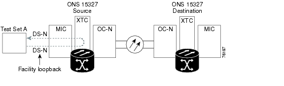
1.2.1 Perform a Facility Loopback on a Source XTC Port
The facility loopback test is performed on the node source port in the network circuit; in this example, the test is routed through the MIC card and performed on the XTC port in the source node. Completing a successful facility loopback on this port isolates the cabling, MIC card, and XTC card as possible failure points. Figure 1-7 shows an example of a facility loopback on a source node XTC port.
Figure 1-7 Facility Loopback on a Source XTC Port
Caution
Note
Procedure: Create the Facility Loopback on the Source XTC Port
Step 1
Use appropriate cabling to attach the transmit (Tx) and receive (Rx) terminals of the electrical test set to the MIC card, which interfaces with the XTC card. Both Tx and Rx connect to the same port. Adjust the test set accordingly.
Step 2
a.
b.
c.
d.
e.
f.
Note
Step 3
Procedure: Test the Facility Loopback
Step 1
Step 2
Step 3
a.
•
•
•
•
•
b.
Step 4
Step 5
Procedure: Test the DS-N Cabling
Step 1
If a cable known to be good is not available, test the suspect cable with a test set. Remove the suspect cable from the MIC and connect the cable to the Tx and Rx terminals of the test set. Run traffic to determine whether the cable is good or suspect.
Step 2
Step 3
a.
b.
•
•
•
•
•
c.
Step 4
Step 5
Procedure: Test the XTC Card
Step 1
Step 2
Step 3
a.
b.
c.
•
•
•
•
•
d.
Step 4
Step 5
Procedure: Test the MIC Cabling
Step 1
If a good cable is not available, test the suspect cable with a test set. Remove the suspect cable and connect the cable to the Tx and Rx terminals of the test set. Run traffic to determine whether the cable is good or defective.
Step 2
Step 3
a.
b.
•
•
•
•
•
c.
Step 4
Step 5
Procedure: Test the MIC Card
Step 1
Step 2
Step 3
a.
b.
c.
•
•
•
•
•
Step 4
Step 5
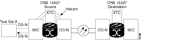
1.2.2 Perform a Hairpin on a Source Node XTC Port
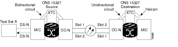
The hairpin test is performed on the first XTC card in the network circuit. A hairpin circuit uses the same port for both source and destination. Completing a successful hairpin through this card isolates the possibility that the source XTC card is the cause of the faulty circuit. Figure 1-8 shows an example of a hairpin circuit on a source node XTC port.
Figure 1-8 Hairpin Circuit on a Source Node XTC Port
Note
Procedure: Create the Hairpin on the Source Node Port
Step 1
•
•
Adjust the test set accordingly.
Step 2
a.
b.
c.
d.
e.
f.
Step 3
Step 4
Procedure: Test the Hairpin Circuit
Step 1
Step 2
Step 3
a.
•
•
•
•
•
b.
Step 4
Step 5
Procedure: Test the Alternate Source XTC Card
Step 1
a.
b.
c.
d.
e.
f.
•
•
•
Step 2
Step 3
a.
•
•
•
•
•
b.
Step 4
Step 5
Procedure: Retest the Original Source XTC Card
Step 1
Step 2
Step 3
a.
b.
c.
•
•
•
•
•
d.
Step 4
Clear the hairpin circuit:
•
•
•
•
•
Step 5
1.2.3 Perform a Terminal Loopback on a Destination XTC Port
The terminal loopback test is performed on the node destination port in the circuit; in this example, the XTC port in the destination node. First, create a bidirectional circuit that starts on the source node DS-N port and terminates on the destination node DS-N port. Then proceed with the terminal loopback test. Completing a successful terminal loopback to a destination node XTC port verifies that the circuit is good up to the destination XTC. Figure 1-9 shows an example of a terminal loopback on a destination node XTC port.
Figure 1-9 Terminal Loopback on a Destination XTC Port
Caution
Procedure: Create the Terminal Loopback on a Destination XTC Port
Step 1
a.
b.
c.
Step 2
a.
b.
c.
d.
e.
f.
Step 3
Note
Note
Step 4
a.
•
•
b.
c.
d.
e.
f.
g.
Step 5
Procedure: Test the Terminal Loopback Circuit on the Destination XTC Port
Step 1
Step 2
Step 3
a.
•
•
•
•
•
•
b.
•
•
•
•
c.
Step 4
Step 5
Procedure: Test the Destination XTC Card
Step 1
Step 2
Step 3
a.
b.
c.
•
•
•
•
•
•
d.
•
•
•
•
Step 4
1.2.4 Perform a Hairpin on a Destination Node XTC Port
The hairpin test is preformed on the XTC card in the destination node. To perform this test, you must also create a bidirectional circuit from the source MIC card to the source OC-N node in the transmit direction. Creating the bidirectional circuit and completing a successful hairpin isolates the possibility that the source and destination OC-N cards, the source and destination XTC cards, or the fiber span is responsible for the faulty circuit. Figure 1-10 shows an example of a hairpin circuit on a destination node XTC card.
Figure 1-10 Hairpin on a Destination Node XTC Card
Procedure: Create the Hairpin Loopback Circuit on the Destination Node XTC Card
Step 1
Use appropriate cabling to attach the Tx and Rx terminals of the electrical test set to the EIA connectors or DSx panel for the port you are testing. The Tx and Rx terminals connect to the same port. Adjust the test set accordingly.
Step 2
a.
b.
c.
d.
e.
f.
Step 3
Step 4
Note
For example, in a typical east-to-west slot configuration, a Slot 1 (east) OC-N card on the source node is one end of the fiber span, and the Slot 2 (west) OC-N card on the destination node is the other end.
a.
b.
c.
d.
e.
f.
Step 5
Step 6
Step 7
Procedure: Test the Hairpin Circuit
Step 1
Step 2
Step 3
a.
•
•
•
•
•
b.
Step 4
Step 5
Procedure: Test the Alternate Destination XTC Card
Step 1
Caution
Note
Step 2
Step 3
a.
•
•
•
•
•
b.
Step 4
Step 5
Procedure: Retest the Original Destination XTC Card
Step 1
Note
Step 2
Step 3
a.
b.
c.
•
•
•
•
d.
Step 4
Clear the hairpin circuit:
•
•
•
•
Step 5
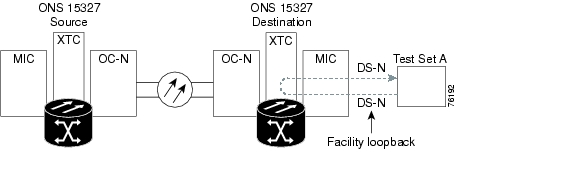
1.2.5 Perform a Facility Loopback on a Destination XTC Card
The facility loopback test is performed on the last port in the circuit, in this case the XTC port in the destination node. Completing a successful facility loopback on this port isolates the possibility that the destination node cabling, MIC card, or line interface is responsible for a faulty circuit. Figure 1-11 shows an example of a facility loopback on a destination node XTC port.
Figure 1-11 Facility Loopback on a Destination XTC Card
Caution
Note
Procedure: Create a Facility Loopback Circuit on a Destination XTC Port
Step 1
a.
b.
c.
Step 2
a.
b.
c.
d.
e.
Note
Step 3
Procedure: Test the Facility Loopback Circuit
Step 1
Step 2
Step 3
a.
•
•
•
•
•
b.
Step 4
Step 5
Procedure: Test the DS-N Cabling
Step 1
If a good cable is not available, test the suspect cable with a test set. Remove the suspect cable from the MIC and connect the cable to the Tx and Rx terminals of the test set. Run traffic to determine whether the cable is good or suspect.
Step 2
Step 3
a.
b.
•
•
•
•
•
c.
Step 4
Step 5
Procedure: Test the XTC Card
Step 1
Step 2
Step 3
a.
b.
c.
•
•
•
•
•
d.
Step 4
Step 5
Procedure: Test the MIC Card
Step 1
Step 2
Step 3
a.
b.
c.
•
•
•
•
•
d.
Step 4
1.3 Identify Points of Failure on an OC-N Circuit Path
Facility loopbacks, terminal loopbacks, and cross-connect loopback circuits are often used together to test the circuit path through the network or to logically isolate a fault. Performing a loopback test at each point along the circuit path systematically isolates possible points of failure.
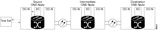
The example in this section tests an OC-N circuit on a three-node BLSR. Using a series of facility loopbacks and terminal loopbacks, the path of the circuit is traced and the possible points of failure are tested and eliminated. A logical progression of seven network test procedures applies to this sample scenario:
1.
2.
3.
4.
5.
6.
7.
Note
Note
1.3.1 Perform a Facility Loopback on a Source-Node OC-N Port
The facility loopback test is performed on the node source port in the network circuit, in this example, the source OC-N port in the source node. Completing a successful facility loopback on this port isolates the OC-N port as a possible failure point. Figure 1-12 shows an example of a facility loopback on a circuit source OC-N port.
Figure 1-12 Facility Loopback on a Circuit Source OC-N Port
Caution
Procedure: Create the Facility Loopback on the Source OC-N Port
Step 1
Use appropriate cabling to attach the Tx and Rx terminals of the optical test set to the port you are testing. The Tx and Rx terminals connect to the same port. Adjust the test set accordingly.
Step 2
a.
b.
c.
d.
e.
f.
Note
Step 3
Procedure: Test the Facility Loopback Circuit
Step 1
Step 2
Step 3
a.
•
•
•
•
•
b.
Step 4
Step 5
Procedure: Test the OC-N Card
Step 1
Step 2
Step 3
a.
b.
c.
•
•
•
•
•
Step 4
1.3.2 Perform a Cross-Connect Loopback on the Source OC-N Port
The cross-connect loopback test occurs on the cross-connect card (XCT) in a network circuit. A cross-connect loopback circuit uses the same port for both source and destination. Completing a successful cross-connect loopback through the XCT card isolates the possibility that the XCT card is the cause of the faulty circuit. Figure 1-13 shows an example of a cross-connect loopback on a source OC-N port.
Figure 1-13 Cross-Connect Loopback on a Source OC-N Port
Step 1
a.
b.
c.
Step 2
a.
b.
c.
d.
e.
Step 3
a.
b.
c.
d.
Step 4
Procedure: Test the Cross-Connect Loopback Circuit
Step 1
Step 2
Step 3
a.
•
•
•
•
b.
Step 4
Step 5
Procedure: Test the Standby XTC Card
Step 1
a.
b.
c.
d.
e.
f.
•
•
•
Step 2
The test traffic now travels through the alternate cross-connect card.
Step 3
a.
•
•
•
•
•
b.
Step 4
Step 5
Procedure: Retest the Original XTC Card
Step 1
a.
b.
c.
d.
e.
f.
•
•
•
Step 2
Step 3
a.
b.
c.
•
•
•
•
d.
Step 4
Clear the cross-connect loopback:
a.
b.
c.
d.
Step 5
1.3.3 Perform a Terminal Loopback on a Source-Node OC-N Port
The terminal loopback test is performed on the node destination port in the circuit, in this example, the destination OC-N port in the source node. First, create a bidirectional circuit that starts on the node source OC-N port and loops back on the node destination OC-N port. Then proceed with the terminal loopback test. Completing a successful terminal loopback to a node destination OC-N port verifies that the circuit is good up to the destination OC-N. Figure 1-14 shows an example of a terminal loopback on a source node OC-N port.
Figure 1-14 Terminal Loopback on a Source-Node OC-N Port
Caution
Procedure: Create the Terminal Loopback on a Source Node OC-N Port
Step 1
a.
b.
c.
Step 2
a.
b.
c.
d.
e.
f.
Step 3
Note
Step 4
a.
b.
c.
d.
e.
f.
Step 5
Procedure: Test the Terminal Loopback Circuit
Step 1
Step 2
Step 3
a.
•
•
•
•
•
•
b.
•
•
•
•
c.
Step 4
Step 5
Procedure: Test the OC-N Card
Step 1
Step 2
Step 3
a.
b.
c.
•
•
•
•
•
•
d.
•
•
•
•
Step 4
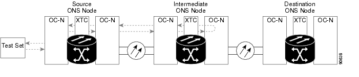
1.3.4 Perform a Facility Loopback on an Intermediate-Node OC-N Port
The facility loopback test is performed on the node source port in the network circuit, in this example, the source OC-N port in the intermediate node. Completing a successful facility loopback on this port isolates the OC-N port as a possible failure point. Figure 1-15 shows an example of a facility loopback on a intermediate node circuit source OC-N port.
Figure 1-15 Facility Loopback on an Intermediate-Node OC-N Port
Caution
Procedure: Create the Facility Loopback on an Intermediate-Node OC-N Port
Step 1
a.
b.
c.
Step 2
a.
b.
c.
d.
e.
f.
Step 3
Note
Step 4
a.
•
•
b.
c.
d.
e.
f.
g.
Note
Step 5
Procedure: Test the Facility Loopback Circuit
Step 1
Step 2
Step 3
a.
•
•
•
•
•
b.
•
•
•
•
c.
Step 4
Step 5
Procedure: Test the OC-N Card
Step 1
Step 2
Step 3
a.
b.
c.
•
•
•
•
•
d.
•
•
•
•
Step 4
1.3.5 Perform a Terminal Loopback on an Intermediate-Node OC-N Port
The terminal loopback test is performed on the node destination port in the circuit, in this example, the destination OC-N port in the intermediate node. First, create a bidirectional circuit that starts on the node source OC-N port and loops back on the node destination OC-N port. Then proceed with the terminal loopback test. Completing a successful terminal loopback to a node destination OC-N port verifies that the circuit is good up to the destination OC-N port. Figure 1-16 shows an example of a terminal loopback on an intermediate node destination OC-N port.
Figure 1-16 Terminal Loopback on an Intermediate-Node OC-N Port
Caution
Procedure: Create the Terminal Loopback on an Intermediate-Node OC-N Port
Step 1
a.
b.
c.
Step 2
a.
b.
c.
d.
e.
f.
Step 3
Note
Step 4
a.
•
•
b.
c.
d.
e.
f.
g.
Step 5
Procedure: Test the Terminal Loopback Circuit
Step 1
Step 2
Step 3
a.
•
•
•
•
•
•
b.
•
•
•
•
c.
Step 4
Step 5
Procedure: Test the OC-N Card
Step 1
Step 2
Step 3
a.
b.
c.
•
•
•
•
•
•
d.
•
•
•
•
Step 4
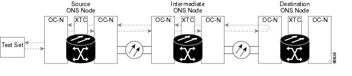
1.3.6 Perform a Facility Loopback on a Destination-Node OC-N Port
The facility loopback test is performed on the node source port in the network circuit, in this example, the source OC-N port in the destination node. Completing a successful facility loopback on this port isolates the OC-N port as a possible failure point. Figure 1-17 shows an example of a facility loopback on a destination node circuit source OC-N port.
Figure 1-17 Facility Loopback on a Destination Node OC-N Port
Caution
Procedure: Create the Facility Loopback on a Destination Node OC-N Port
Step 1
a.
b.
c.
Step 2
a.
b.
c.
d.
e.
f.
Step 3
Note
Step 4
a.
•
•
b.
c.
d.
e.
f.
g.
Note
Step 5
Procedure: Test the Facility Loopback Circuit
Step 1
Step 2
Step 3
a.
•
•
•
•
•
b.
•
•
•
•
c.
Step 4
Step 5
Procedure: Test the OC-N Card
Step 1
Step 2
Step 3
a.
b.
c.
•
•
•
•
•
d.
•
•
•
•
Step 4
1.3.7 Perform a Terminal Loopback on a Destination Node OC-N Port
The terminal loopback test is performed on the node destination port in the circuit, in this example, the destination OC-N port in the destination node. First, create a bidirectional circuit that starts on the node source OC-N port and loops back on the node destination OC-N port. Then proceed with the terminal loopback test. Completing a successful terminal loopback to a node destination OC-N port verifies that the circuit is good up to the destination OC-N. Figure 1-18 shows an example of a terminal loopback on an intermediate node destination OC-N port.
Figure 1-18 Terminal Loopback on a Destination Node OC-N Port
Caution
Procedure: Create the Terminal Loopback on a Destination Node OC-N Port
Step 1
a.
b.
c.
Step 2
a.
b.
c.
d.
e.
f.
Step 3
Note
Step 4
a.
•
•
b.
c.
d.
e.
f.
g.
Step 5
Procedure: Test the Terminal Loopback Circuit
Step 1
Step 2
Step 3
a.
•
•
•
•
•
•
b.
•
•
•
•
c.
Step 4
Step 5
Procedure: Test the OC-N Card
Step 1
Step 2
Step 3
a.
b.
c.
•
•
•
•
•
•
d.
•
•
•
•
Step 4
1.4 Restoring the Database and Default Settings
This section contains troubleshooting procedures for node operation errors that require restoration of software data or the default node setup.
1.4.1 Restore the Node Database
Symptom: One or more node(s) are not functioning properly or have incorrect data.
Table 1-1 describes the potential cause of the symptom and the solution.
Table 1-1 Restore the Node Database
Incorrect or corrupted node database.
Perform a Restore the Database procedure. Refer to the "Restore the Database" procedure.
Procedure: Restore the Database
Note
Caution
Caution
Step 1
a.
b.
A Java Console window displays the CTC file download status. The web browser displays information about your Java and system environments. If this is the first login, CTC caching messages display while CTC files are downloaded to your computer. The first time you connect to an ONS 15327, this process can take several minutes. After the download, the CTC Login dialog box displays.
c.
Step 2
Step 3
a.
b.
Step 4
Step 5
Step 6
Step 7
Step 8
Caution
Step 9
The Restore Database dialog box monitors the file transfer.
Step 10
Step 11
Step 12
1.4.2 Restore the Node to Factory Configuration
Symptom A node has both XTC cards in standby state, and you are unable reset the XTC cards to make the node functional.
Table 1-2 describes the potential cause(s) of the symptom and the solution(s).
Table 1-2 Restore the Node to Factory Configuration
Failure of both XTC cards in the node.
To restore the node to factory configuration, see the "Use the Reinitialization Tool to Clear the Database and Upload Software (Windows)" procedure or the "Use the Reinitialization Tool to Clear the Database and Upload Software (UNIX)" procedure.
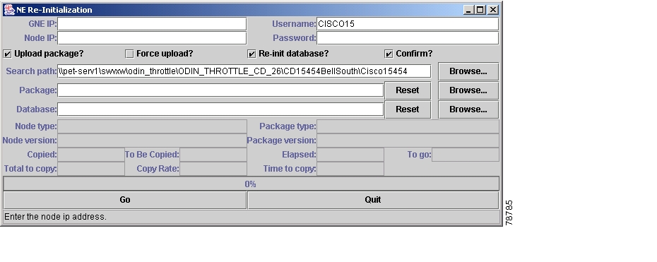
This procedure describes how to restore the node to factory configuration using the RE-INIT.jar JAVA file, which is referred to as the reinitialization tool in this documentation. Use this tool to upload the software package and/or restore the database after it has been backed up. You need the CD containing the latest software, the node's NE defaults, and the recovery tool.
Replacement of both XTC cards at the same time.
Caution
Caution
Note
Note
Procedure: Use the Reinitialization Tool to Clear the Database and Upload Software (Windows)
Note
Step 1
Step 2
Step 3
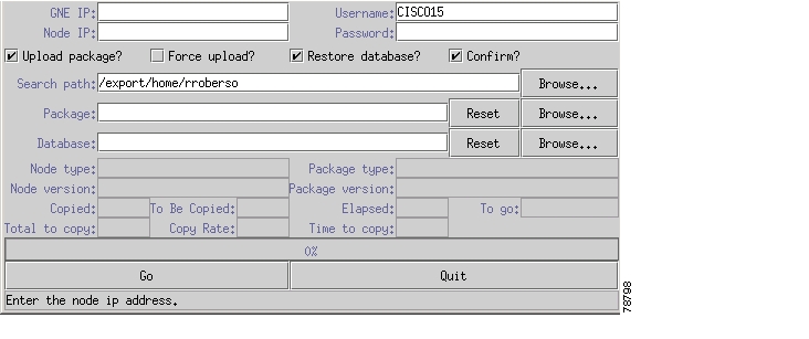
Step 4
Figure 1-19 Reinitialization Tool in Windows
Step 5
Step 6
Step 7
Step 8
Caution
Caution
Step 9
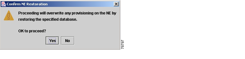
Step 10
Figure 1-20 Confirm NE Restoration
Step 11
Note
Step 12
Step 13
Step 14
Procedure: Use the Reinitialization Tool to Clear the Database and Upload Software (UNIX)
Note
Note
Step 1
Step 2
Step 3
Figure 1-21 Reinitialization Tool in UNIX
Step 4
Step 5
Step 6
Step 7
Caution
Caution
Step 8
Step 9
Step 10
Note
Step 11
Step 12
Step 13
1.5 PC Connectivity Troubleshooting
This section contains troubleshooting procedures for PC and network connectivity to the ONS 15327.
1.5.1 Unable to Verify the IP Configuration of Your PC
Symptom When connecting your PC to the ONS 15327, you are unable to successfully ping the IP address of your PC to verify the IP configuration.
Table 1-3 describes the potential cause(s) of the symptom and the solution(s).
Table 1-3 Unable to Verify the IP Configuration of Your PC
The IP address is typed incorrectly.
Verify that the IP address used to ping the PC matches the IP address displayed when the Windows IP Configuration information is retrieved from the system.
Verify the IP configuration of your PC, see the "Verify the IP Configuration of Your PC" procedure.
If this procedure is unsuccessful, contact your Network Administrator for instructions to correct the IP configuration of your PC.
The IP configuration of your PC is not properly set.
Procedure: Verify the IP Configuration of Your PC
Step 1
Step 2
Step 3
•
•
The Windows IP configuration information is displayed, including the IP address, subnet mask, and the default gateway.
Step 4
Step 5
If the DOS window displays multiple (usually four) replies, the IP configuration is working properly.
If you do not receive a reply, your IP configuration might not be properly set. Contact your Network Administrator for instructions to correct the IP configuration of your PC.
1.5.2 Browser Login Does Not Launch Java
Symptom The message "Loading Java Applet" does not appear and the JRE does not launch during the initial login.
Table 1-4 describes the potential cause(s) of the symptom and the solution(s).
Table 1-4 Browser Login Does Not Launch Java
The PC operating system and browser are not properly configured.
Reconfigure the PC operating system java plug-in control panel and the browser settings.
See the "Reconfigure the PC Operating System Java Plug-in Control Panel" procedure and the "Reconfigure the Browser" procedure.
Procedure: Reconfigure the PC Operating System Java Plug-in Control Panel
Step 1
Step 2
a.
b.
c.
d.
Step 3
Step 4
Step 5
Step 6
Step 7
Step 8
Procedure: Reconfigure the Browser
Step 1
Step 2
a.
b.
c.
d.
e.
f.
•
•
g.
h.
i.
Step 3
a.
b.
c.
d.
Step 4
Step 5
Step 6
Step 7
1.5.3 Unable to Verify the NIC Connection on Your PC
Symptom When connecting your PC to the ONS 15327, you are unable to verify that the NIC connection is working properly because the link LED is not illuminated or flashing.
Table 1-5 describes the potential cause(s) of the symptom and the solution(s).
Table 1-5 Unable to Verify the NIC Connection on Your PC
The Category 5 cable is not plugged in properly.
Confirm both ends of the cable are properly inserted. If the cable is not fully inserted due to a broken locking clip, the cable should be replaced.
The Category 5 cable is damaged.
Ensure that the cable is in good condition. If in doubt, use a cable known to be good. Often, cabling is damaged due to pulling or bending.
Incorrect type of Category 5 cable is being used.
If connecting an ONS 15327 directly to your laptop/PC or a router, use a straight-through Category 5 cable. When connecting the ONS 15327 to a hub or a LAN switch, use a crossover Category 5 cable.
For details on the types of Category 5 cables, see the "Crimp Replacement LAN Cables" section.
The NIC is improperly inserted or installed.
If you are using a PCMCIA-based NIC, remove and re-insert the NIC to make sure the NIC is fully inserted.
If the NIC is built into the laptop/PC, verify that the NIC is not faulty.
The NIC is faulty.
Confirm that the NIC is working properly. If you have no issues connecting to the network (or any other node), then the NIC should be working correctly.
If you have difficulty connecting to the network (or any other node), then the NIC might be faulty and needs to be replaced.
1.5.4 Verify PC Connection to the ONS 15327 (Ping)
Symptom The TCP/IP connection is established and then lost, and a DISCONNECTED alarm appears on CTC.
Table 1-6 describes the potential cause of the symptom and the solution.
Table 1-6 Verify PC Connection to ONS 15327 (Ping)
A lost connection between the PC and the ONS 15327.
Use a standard ping command to verify the TCP/IP connection between the PC and the ONS 15327 XTC card. A ping command works if the PC connects directly to the XTC card or uses a LAN to access the XTC card.
See the "Ping the ONS 15327" procedure.
Procedure: Ping the ONS 15327
Step 1
a.
b.
Step 2
ping ONS-15327-IP-addressFor example:
ping 192.1.0.2.Step 3
Step 4
Step 5
Step 6
1.5.5 The IP Address of the Node is Unknown
Symptom The IP address of the node is unknown and you are unable to log in.
Table 1-7 describes the potential cause of the symptom and the solution.
Procedure: Retrieve Unknown Node IP Address
Step 1
Step 2
Step 3
Step 4
1.6 CTC Operation Troubleshooting
This section contains troubleshooting procedures for CTC login or operation problems.
1.6.1 Unable to Launch CTC Help After Removing Netscape
Symptom After removing Netscape and running CTC using Internet Explorer, the user is unable to launch the CTC Help and receives an "MSIE is not the default browser" error message.
Table 1-8 describes the potential cause of the symptom and the solution.
Table 1-8 Unable to Launch CTC Help After Removing Netscape
Loss of association between browser and Help files.
When the CTC software and Netscape are installed, the Help files are associated with Netscape by default. When you remove Netscape, the Help files are not automatically associated with Internet Explorer as the default browser.
Set Internet Explorer as the default browser so that CTC will associate the Help files to the correct browser.
See the "Set Internet Explorer as the Default Browser for CTC" procedure to associate the CTC Help files to the correct browser.
Procedure: Set Internet Explorer as the Default Browser for CTC
Step 1
Step 2
Step 3
Step 4
Step 5
Step 6
Step 7
1.6.2 Unable to Change Node View to Network View
Symptom When activating a large, multinode BLSR from Software Release 3.2 to Software Release 3.3, some of the nodes appear grayed out. Logging into the new CTC, the user is unable to change node view to network view on any and all nodes, from any workstation. This is accompanied by an "Exception occurred during event dispatching: java.lang.OutOfMemoryError" in the java window.
Table 1-9 describes the potential cause of the symptom and the solution.
Table 1-9 Browser Stalls When Downloading Files From XTC
The large, multinode BLSR requires more memory for the graphical user interface (GUI) environment variables.
Reset the system or user CTC_HEAP environment variable to increase the memory limits.
See the "Reset the CTC_HEAP Environment Variable for Windows" procedure or the "Reset the CTC_HEAP Environment Variable for Solaris" procedure to enable the CTC_HEAP variable change.
Note
Procedure: Reset the CTC_HEAP Environment Variable for Windows
Step 1
Step 2
Step 3
Step 4
Step 5
Step 6
Step 7
Step 8
Step 9
Step 10
Procedure: Reset the CTC_HEAP Environment Variable for Solaris
Step 1
Step 2
Step 3
% setenv CTC_HEAP 256Step 4
1.6.3 Browser Stalls When Downloading CTC JAR Files from XTC
Symptom The browser stalls or hangs when downloading a CTC JAR file from the XTC card.
Table 1-10 describes the potential cause of the symptom and the solution.
Table 1-10 Browser Stalls When Downloading JAR File from XTC
McAfee VirusScan software might be interfering with the operation. The problem occurs when the VirusScan Download Scan is enabled on McAfee VirusScan 4.5 or later.
Disable the VirusScan Download Scan feature. See the "Disable the VirusScan Download Scan" procedure.
Procedure: Disable the VirusScan Download Scan
Step 1
Step 2
Step 3
Step 4
Step 5
Step 6
Step 7
Step 8
Step 9
1.6.4 CTC Does Not Launch
Symptom CTC does not launch; usually an error message appears before the login window displays.
Table 1-11 describes the potential cause of the symptom and the solution.
Table 1-11 CTC Does Not Launch
The Netscape browser cache might point to an invalid directory.
Redirect the Netscape cache to a valid directory. See the "Redirect the Netscape Cache to a Valid Directory" procedure.
Procedure: Redirect the Netscape Cache to a Valid Directory
Step 1
Step 2
Step 3
Step 4
Step 5
The cache file location is usually C:\ProgramFiles\Netscape\Users\yourname\cache. The yourname segment of the file location is often the same as the user name.
1.6.5 Sluggish CTC Operation or Login Problems
Symptom You experience sluggish CTC operation or have problems logging into CTC.
Table 1-12 describes the potential cause of the symptom and the solution.
Table 1-12 Sluggish CTC Operation or Login Problems
The CTC cache file might be corrupted or might need to be replaced.
Delete the CTC cache file. This operation forces the ONS 15327 to download a new set of JAR files to your computer hard drive. See the "Delete the CTC Cache File Automatically" procedure or the "Delete the CTC Cache File Manually" procedure.
Procedure: Delete the CTC Cache File Automatically
Caution
Step 1
Step 2
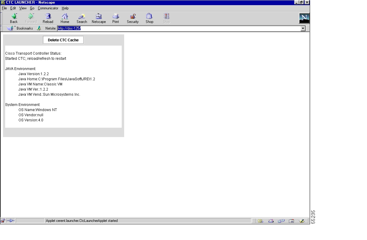
Step 3
Figure 1-22 Deleting the CTC Cache
Procedure: Delete the CTC Cache File Manually
Caution
Step 1
Step 2
Step 3
Step 4
Step 5
1.6.6 Node Icon is Gray on CTC Network View
Symptom The CTC network view shows one or more node icons as gray in color and without a node name.
Table 1-13 describes the potential cause(s) of the symptom and the solution(s).
Table 1-13 Node Icon is Gray on CTC Network View
Different CTC releases are not recognizing each other.
Usually accompanied by an INCOMPATIBLE-SW alarm. Correct the core version build as described in the "Different CTC Releases Do Not Recognize Each Other" section.
A username/password mismatch.
Usually accompanied by a NOT-AUTHENTICATED alarm. Correct the username and password as described in the "Username or Password Does Not Match the XTC Information" section.
No IP connectivity between nodes.
Usually accompanied by Ethernet-specific alarms. Verify the Ethernet connections as described in the "Ethernet Connections" section.
A lost DCC connection.
Usually accompanied by an EOC alarm. Clear the EOC alarm and verify the DCC connection as described in the "2.6.49 EOC" section on page 2-48.
1.6.7 CTC Cannot Launch Due to Applet Security Restrictions
Symptom The error message "Unable to launch CTC due to applet security restrictions" appears after you enter the IP address in the browser window.
Table 1-14 describes the potential cause(s) of the symptom and the solution(s).
Table 1-14 CTC Cannot Launch Due to Applet Security Restrictions
Did not execute the javapolicyinstall.bat file.
1.
2.
The java.policy file might be incomplete.
Procedure: Manually Edit the java.policy File
Step 1
Step 2
// Insert this into the system-wide or a per-user java.policy file.// DO NOT OVERWRITE THE SYSTEM-WIDE POLICY FILE--ADD THESE LINES!grant codeBase "http://*/fs/LAUNCHER.jar" {permission java.security.AllPermission;};Step 3
Step 4
CTC should now start correctly.
Step 5
1.6.8 Java Runtime Environment Incompatible
Symptom The CTC application does not run properly.
Table 1-15 describes the potential cause of the symptom and the solution.
Table 1-15 Java Runtime Environment Incompatible
The compatible Java 2 JRE is not installed.
The Java 2 JRE contains the Java virtual machine, runtime class libraries, and Java application launcher that are necessary to run programs written in the Java programming language.
The ONS 15327 CTC is a Java application. A Java application, unlike an applet, cannot rely completely on a web browser for installation and runtime services. When you run an application written in the Java programming language, you need the correct JRE installed. The correct JRE for each CTC software release is included on the Cisco ONS 15327 software CD and on the Cisco ONS 15327 documentation CD. See the "Launch CTC to Correct the Core Version Build" procedure.
If you are running multiple CTC software releases on a network, the JRE installed on the computer must be compatible with all of the releases that you are running. See Table 1-16.
Table 1-16 shows JRE compatibility with ONS 15327 software releases.
Procedure: Launch CTC to Correct the Core Version Build
Step 1
Step 2
Step 3
Step 4
Note
1.6.9 Different CTC Releases Do Not Recognize Each Other
Symptom This situation is often accompanied by the INCOMPATIBLE-SW alarm.
Table 1-17 describes the potential cause of the symptom and the solution.
Table 1-17 Different CTC Releases Do Not Recognize Each Other
The software loaded on the connecting workstation and the software on the XTC card are incompatible.
This occurs when the XTC software is upgraded but the PC has not yet upgraded the compatible CTC JAR file. It also occurs on login nodes with compatible software that encounter other nodes in the network that have a newer software version.
Note
See the "Launch CTC to Correct the Core Version Build" procedure.
Procedure: Launch CTC to Correct the Core Version Build
Step 1
Step 2
Step 3
Step 4
1.6.10 Username or Password Does Not Match the XTC Information
Symptom A mismatch often occurs concurrently with a NOT-AUTHENTICATED alarm.
Table 1-18 describes the potential cause(s) of the symptom and the solution(s).
Procedure: Verify Correct Username and Password
Step 1
Step 2
Step 3
1.6.11 No IP Connectivity Exists Between Nodes
Symptom The nodes have a gray icon that is usually accompanied by alarms.
Table 1-19 describes the potential cause of the symptom and the solution.
Table 1-19 No IP Connectivity Exists Between Nodes
Lost Ethernet connection
Usually, this condition is accompanied by Ethernet-specific alarms. Verify the Ethernet connections as described in the "Ethernet Connections" section.
1.6.12 DCC Connection Lost
Symptom The node is usually accompanied by alarms and the nodes in the network view have a gray icon. This symptom is usually accompanied by an EOC alarm.
Table 1-20 describes the potential cause of the symptom and the solution.
Table 1-20 DCC Connection Lost
A lost DCC connection
Usually, this condition is accompanied by an EOC alarm. Clear the EOC alarm and verify the DCC connection as described in the "2.6.49 EOC" section on page 2-48.
1.6.13 "Path in Use" Error When Creating a Circuit
Symptom While creating a circuit, you get a "Path in Use" error that prevents you from completing the circuit creation.
Table 1-21 describes the potential cause of the symptom and the solution.
Table 1-21 "Path in Use" Error When Creating a Circuit
Another user has already selected the same source port to create another circuit
CTC does not remove a card or port from the available list until a circuit is completely provisioned. If two users simultaneously select the same source port to create a circuit, the first user to complete circuit provisioning gets use of the port. The other user gets the "Path in Use" error.
See the "Cancel the Circuit Creation and Start Over" procedure.
Procedure: Cancel the Circuit Creation and Start Over
Step 1
•
•
Step 2
Step 3
1.6.14 Calculate and Design IP Subnets
Symptom You cannot calculate or design IP subnets on the ONS 15327.
Table 1-22 describes the potential cause(s) of the symptom and the solution(s).
Table 1-22 Calculate and Design IP Subnets
The IP capabilities of the ONS 15327 require specific calculations to properly design IP subnets.
Cisco provides a free online tool to calculate and design IP subnets. Go to http://www.cisco.com/techtools/ip_addr.html. For information about ONS 15327 IP capability, refer to the Cisco ONS 15327 Reference Manual.
1.6.15 Ethernet Connections
Symptom Ethernet connections appear to be broken or are not working properly.
Table 1-23 describes the potential cause(s) of the symptom and the solution(s).
Table 1-23 Ethernet Connections
Improperly seated connections
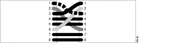
You can fix most connectivity problems in an Ethernet network by following a few guidelines. See Figure 1-23 when consulting the steps in the "Verify Ethernet Connections" procedure.
Incorrect connections
Figure 1-23 Ethernet Connectivity Reference
Procedure: Verify Ethernet Connections
Step 1
Step 2
Step 3
Step 4
Step 5
Step 6
a.
b.
c.
d.
e.
Step 7
a.
b.
c.
Step 8
Step 9
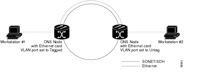
1.6.16 VLAN Cannot Connect to Network Device from Untag Port
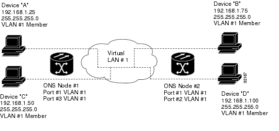
Symptom Networks that have a VLAN with one ONS 15327 Ethernet card port set to Tagged and one ONS 15327 Ethernet card set to Untag might have difficulty implementing Address Resolution Protocol (ARP) for a network device attached to the Untag port ( Figure 1-24). They might also see a higher than normal runt packets count at the network device attached to the Untag port.This symptom/limitation also exists when ports within the same card or ports within the same chassis are put on the same VLAN, with a mix of tagged and untagged.
Figure 1-24 VLAN with Ethernet Ports at Tagged and Untag
Table 1-24 describes the potential cause(s) of the symptom and the solution(s).
Table 1-24 VLAN Cannot Connection to Network Device from Untag Port
The Tagged ONS 15327 adds the IEEE 802.1Q tag and the Untag ONS 15327 removes the Q-tag without replacing the bytes. The NIC of the network device categorizes the packet as a runt and drops the packet.
See the "Change VLAN Port Tag and Untagged Settings" procedure.
The solution is to set both ports in the VLAN to Tagged to stop the stripping of the 4 bytes from the data packet and prevents the NIC card in the network access device from recognizing the packet as a runt and dropping it. Network devices with IEEE 802.1Q-compliant NIC cards can accept the tagged packets. Network devices with non-IEEE 802.1Q compliant NIC cards still drop these tagged packets. The solution might require upgrading network devices with non-IEEE 802.1Q compliant NIC cards to IEEE 802.1Q-compliant NIC cards. You can also set both ports in the VLAN to Untag, but you lose IEEE 802.1Q compliance.
Dropped packets can also occur when ARP attempts to match the IP address of the network device attached to the Untag port with the physical MAC address required by the network access layer.
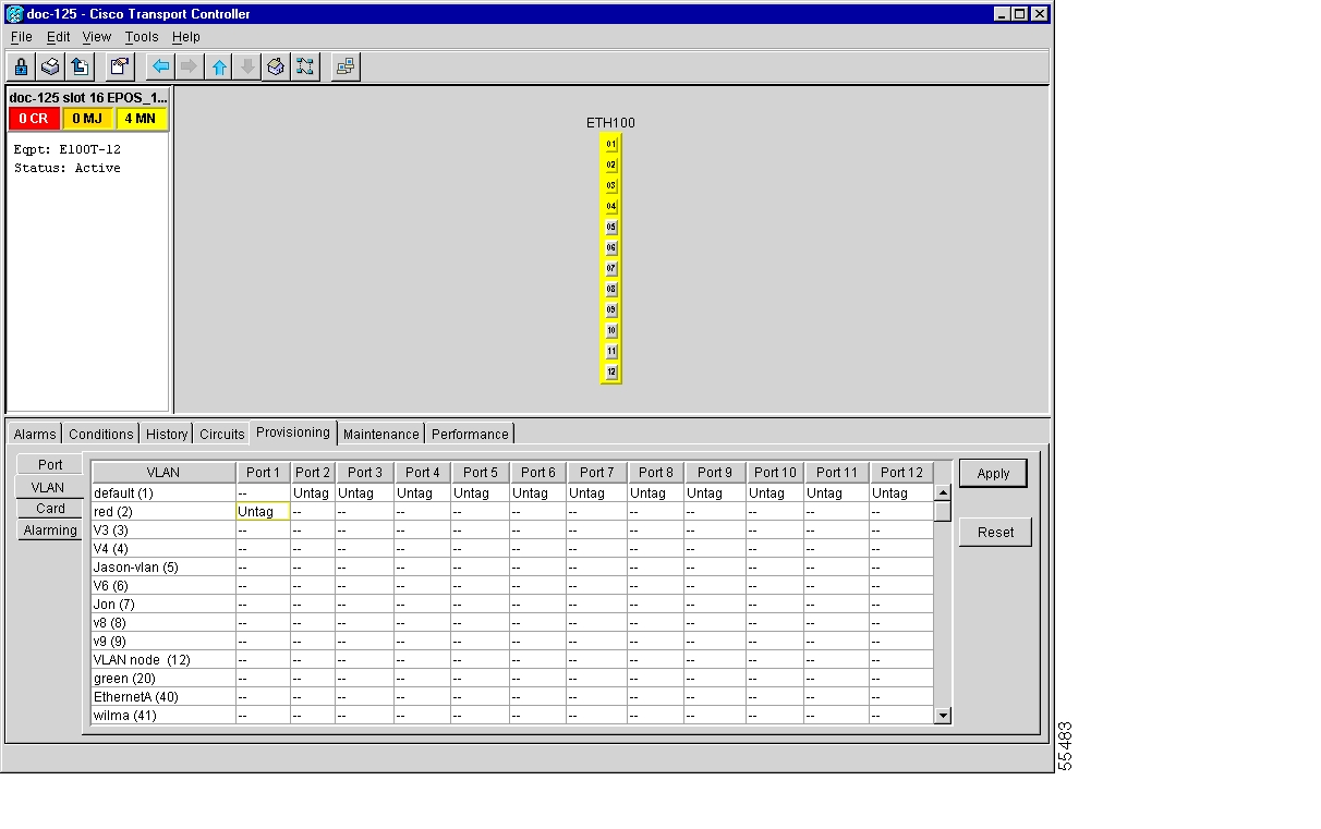
Procedure: Change VLAN Port Tag and Untagged Settings
Step 1
Step 2
Figure 1-25 Configuring VLAN Membership for Individual Ethernet Ports
Step 3
Step 4
Note
Step 5
1.7 Circuits and Timing
This section provides solutions to circuit creation and reporting errors, as well as common timing reference errors and alarms.
1.7.1 Circuit Transitions to Partial State
Symptom An automatic or manual transition of a circuit from one state to another state results in one of the following partial state conditions:
•
•
•
Table 1-25 describes the potential cause(s) of the symptom and the solution(s).
Table 1-25 Circuit in Partial State
During a manual transition, CTC cannot communicate with one of the nodes or one of the nodes is on a version of software that does not support the new state model.
Repeat the manual transition operation. If the partial state persists, determine which node in the circuit is not changing to the desired state. Refer to the "View the State of Circuit Nodes" procedure.
Log onto the circuit node that did not change to the desired state and determine the version of software. If the software on the node is Software R3.3 or earlier, upgrade the software. Refer to the Cisco ONS 15327 Software Upgrade Guide for software upgrade procedures.
Note
During an automatic transition, some path-level defects and/or alarms were detected on the circuit.
Determine which node in the circuit is not changing to the desired state. Refer to the "View the State of Circuit Nodes" procedure.
Log into the circuit node that did not change to the desired state and examine the circuit for path-level defects, improper circuit termination, or alarms. Refer to the Cisco ONS 15327 Procedure Guide for procedures to clear alarms and change circuit configuration settings.
Resolve and clear the defects and/or alarms on the circuit node and verify that the circuit transitions to the desired state.
One end of the circuit is not properly terminated.
Procedure: View the State of Circuit Nodes
Step 1
Step 2
Step 3
Step 4
The State tab window lists the Node, CRS End A, CRS End B, and CRS State for each of the nodes in the circuit.
1.7.2 AIS-V on XTC-28-3 Unused VT Circuits
Symptom An incomplete circuit path causes an alarm indications signal (AIS).
Table 1-26 describes the potential cause of the symptom and the solution.
Table 1-26 AIS-V on XTC-28-3 Unused VT Circuits
The port on the reporting node is in-service but a node upstream on the circuit does not have an OC-N port in service.
An AIS-V indicates that an upstream failure occurred at the virtual tributary (VT) layer. AIS-V alarms also occur on XTC-28-3 VT circuits that are not carrying traffic and on stranded bandwidth.
Perform the "Clear AIS-V on XTC-28-3 Unused VT Circuits" procedure.
Procedure: Clear AIS-V on XTC-28-3 Unused VT Circuits
Step 1
Step 2
Step 3
Step 4
Step 5
Step 6
Step 7
Step 8
Step 9
Step 10
Step 11
Step 12
Step 13
Step 14
Step 15
Step 16
1.7.3 Circuit Creation Error with VT1.5 Circuit
Symptom You might receive an "Error while finishing circuit creation. Unable to provision circuit. Unable to create connection object at node-name" message when trying to create a VT1.5 circuit in CTC.
Table 1-27 describes the potential cause(s) of the symptom and the solution(s).
1.7.4 DS3 Card Does Not Report AIS-P From External Equipment
Symptom A DS-3 card does not report STS AIS-P from the external equipment/line side.
Table 1-28 describes the potential cause of the symptom and the solution.
1.7.5 OC-3 and DCC Limitations
Symptom Limitations to OC-3 and DCC usage.
Table 1-29 describes the potential cause of the symptom and the solution.
1.7.6 ONS 15327 Switches Timing Reference
Symptom Timing references switch when one or more problems occur.
Table 1-30 describes the potential cause(s) of the symptom and the solution(s).
1.7.7 Holdover Synchronization Alarm
Symptom The clock is running at a different frequency than normal and the HLDOVRSYNC alarm appears.
Table 1-31 describes the potential cause of the symptom and the solution.
Table 1-31 Holdover Synchronization Alarm
The last reference input has failed.
The clock is running at the frequency of the last valid reference input. This alarm is raised when the last reference input fails. See the "2.6.94 HLDOVRSYNC" section on page 2-73 for a detailed description of this alarm.
Note
1.7.8 Free-Running Synchronization Mode
Symptom The clock is running at a different frequency than normal and the FRNGSYNC alarm appears.
Table 1-32 describes the potential cause of the symptom and the solution.
Table 1-32 Free-Running Synchronization Mode
No reliable reference input is available.
The clock is using the internal oscillator as its only frequency reference. This occurs when no reliable, prior timing reference is available. See the "2.6.90 FRNGSYNC" section on page 2-71 for a detailed description of this alarm.
1.7.9 Daisy-Chained BITS Not Functioning
Symptom You are unable to daisy-chain the BITS.
Table 1-33 describes the potential cause of the symptom and the solution.
1.7.10 Blinking STAT LED after Installing a Card
Symptom After installing a card, the STAT LED blinks continuously for more than 60 seconds.
Table 1-34 describes the potential cause of the symptom and the solution.
1.8 Fiber and Cabling
This section explains problems typically caused by cabling connectivity errors. It also includes instructions for crimping Category 5 cable and lists the optical fiber connectivity levels.
1.8.1 Bit Errors Appear for a Traffic Card
Symptom A traffic card has multiple bit errors.
Table 1-35 describes the potential cause of the symptom and the solution.
Table 1-35 Bit Errors Appear for a Line Card
Faulty cabling or low optical-line levels.
Bit errors on line (traffic) cards usually originate from cabling problems or low optical-line levels. The errors can be caused by synchronization problems, especially if PJ (pointer justification) errors are reported. Moving cards into different error-free slots isolates the cause. Use a test set whenever possible because the cause of the errors could be external cabling, fiber, or external equipment connecting to the ONS 15327. Troubleshoot cabling problems using the "Network Troubleshooting Tests" section. Troubleshoot low optical levels using the "Faulty Fiber-Optic Connections" section.
1.8.2 Faulty Fiber-Optic Connections
Symptom A line card has multiple SONET alarms and/or signal errors.
Table 1-36 describes the potential cause(s) of the symptom and the solution(s).
Table 1-36 Faulty Fiber-Optic Connections
Faulty fiber-optic connections.
Faulty fiber-optic connections can be the source of SONET alarms and signal errors. See the "Verify Fiber-Optic Connections" procedure.
Faulty Category-5 cables.
Faulty Category-5 cables can be the source of SONET alarms and signal errors. See the "Crimp Replacement LAN Cables" section.
Faulty gigabit interface connectors.
Faulty gigabit interface converters can be the source of SONET alarms and signal errors. See the "Replace Faulty SFP Connectors" section.
Warning
Warning
Warning
Warning
Procedure: Verify Fiber-Optic Connections
Step 1
SM or SM Fiber should be printed on the fiber span cable. ONS 15327 cards do not use multimode fiber.
Step 2
Step 3
a.
b.
c.
d.
e.
Step 4
a.
b.
c.
IR cards transmit a lower output power than LR cards.
d.
e.
•
•
•
Note
Step 5
a.
b.
c.
d.
Step 6
LR cards transmit a higher output power than IR cards. When used with short runs of fiber, an LR transmitter is too powerful for the receiver on the receiving card.
Receiver overloads occur when maximum receiver power is exceeded.
Tip
Tip
1.8.2.1 Crimp Replacement LAN Cables
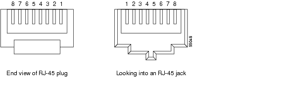
You can crimp your own LAN cables for use with the ONS 15327. Use a cross-over cable when connecting an ONS 15327 to a hub, LAN modem, or switch, and use a LAN cable when connecting an ONS 15327 to a router or workstation. Use #22 or #24 AWG shielded wire with RJ-45 connectors, and a crimping tool. Figure 1-26 shows the layout of an RJ-45 connector.
Figure 1-26 RJ-45 Pin Numbers
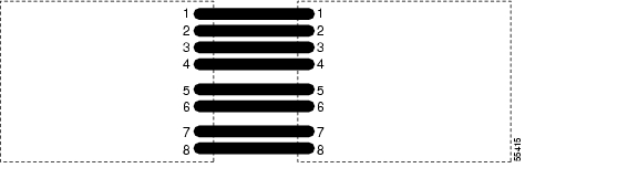
Figure 1-27 shows the layout of a LAN cable.
Figure 1-27 LAN Cable Layout
Table 1-37 shows the pinout of a LAN cable.
Figure 1-28 shows the layout of a cross-over cable.
Figure 1-28 Cross-Over Cable Layout
Table 1-38 shows the pinout of a cross-over cable.
Note
1.8.2.2 Replace Faulty SFP Connectors
Small Form-factor Pluggable (SFP) connectors are hot-swappable and can be installed or removed while the card or shelf assembly is powered and running.
Warning
Warning
SFPs are input/output devices that plug into a Gigabit Ethernet card to link the port with the fiber-optic network. The type of SFP determines the maximum distance that the Ethernet traffic can travel from the card to the next network device. For a description of SFPs and their capabilities, see Table 1-39 and refer to the Cisco ONS 15327 Reference Manual.
Note
Procedure: Remove SFP Connectors
Step 1
Warning
Step 2
Step 3
Procedure: Install SFP Connectors
Step 1
Step 2
Step 3
Step 4
Note
Step 5
Step 6
1.8.2.3 Optical Card Transmit and Receive Levels
Each G1000-2 and OC-N card has a transmit and receive connector on its faceplate. Table 1-40 describes the SFPs and their capabilities.
1.9 Power and LED Tests
This section provides symptoms and solutions for power supply problems, power consumption, and LED indicators.
1.9.1 Power Supply Problems
Symptom Loss of power or low voltage, resulting in a loss of traffic and causing the LCD clock to reset to the default date and time.
Table 1-41 describes the potential cause(s) of the symptom and the solution(s).
Table 1-41 Power Supply Problems
Loss of power or low voltage
The ONS 15327 requires a constant source of DC power to properly function. Input power is -48 VDC. Power requirements range from -42 VDC to -57 VDC.
A newly installed ONS 15327 that is not properly connected to its power supply does not operate. Power problems can be confined to a specific ONS 15327 or can affect several pieces of equipment on the site.
Note
See the "Isolate the Cause of Power Supply Problems" procedure.
Improperly connected power supply
Warning
Warning
Caution
Procedure: Isolate the Cause of Power Supply Problems
Step 1
a.
b.
c.
d.
e.
f.
g.
h.
•
•
•
•
Step 2
a.
b.
c.
1.9.2 Power Consumption for Node and Cards
Symptom You are unable to power up a node or the cards in a node.
Table 1-42 describes the potential cause of the symptom and the solution.
Table 1-42 Power Consumption for Node and Cards
Improper power supply.
Refer to power information in the Cisco ONS 15327 Procedure Guide.
1.9.3 Lamp Test for Card LEDs
Symptom Card LED does not light or you are unsure if LEDs are working properly.
Table 1-43 describes the potential cause of the symptom and the solution.
Procedure: Verify Card LED Operation
Step 1
Step 2
Step 3
Step 4
If an LED does not light up, the LED is faulty. Call the Cisco TAC and fill out an RMA to return the card.
![]()
![]()
![]()
![]()
![]()
![]()
![]()
![]()
Posted: Mon Feb 25 06:41:38 PST 2008
All contents are Copyright © 1992--2008 Cisco Systems, Inc. All rights reserved.
Important Notices and Privacy Statement.