cc/td/doc/product/ong/15327/r34userd
hometocprevnextglossaryfeedbacksearchhelp
PDF

Table Of Contents

Replace Hardware

3.1 Replace the Fan-Tray Assembly

3.2 Remove and Reinsert (Reseat) the Standby XTC

3.3 Inspect, Clean, and Replace the Reusable Air Filter


Replace Hardware


This chapter provides procedures for replacing Cisco ONS 15327 hardware.

Replace the Fan-Tray Assembly—Complete this procedure to replace the fan-tray assembly.

Remove and Reinsert (Reseat) the Standby XTC—Complete this procedure as needed to reset the XTC by performing a card pull.

Inspect, Clean, and Replace the Reusable Air Filter—Complete this procedure to replace a reusable or disposable air filter.

3.1 Replace the Fan-Tray Assembly

You should not need to remove the fan-tray assembly unless a fan failure occurs and you must replace the fan-tray assembly. You cannot replace individual fans.


Step 1 Move any cables that are routed in front of the fan-tray assembly and air filter away so you can easily slide the filter out.

Step 2 Loosen the fastening screw on the failed fan-tray assembly.

Step 3 Grasp the fan tray handle and gently pull it one inch out of the slot and wait until the fans stop turning.

Step 4 When the fans have stopped turning, pull the fan-tray assembly completely out of the shelf assembly. (See Figure 3-1.)

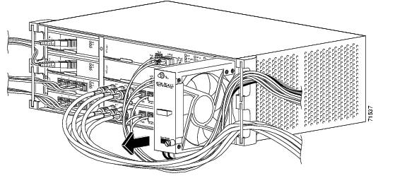
Figure 3-1 Removing the Fan-Tray Assembly

Step 5 Slide the new fan-tray assembly into the shelf until the electrical plug at the rear of the tray plugs into the corresponding receptacle on the back panel ( Figure 3-2).


Caution Do not force the fan-tray assembly into place while installing it. Forcing the fan-tray assembly into place can damage the connectors on the fan tray and/or the connectors on the shelf assembly.

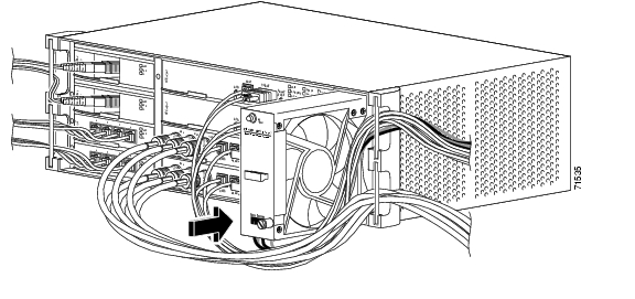
Figure 3-2 Replacing the Fan-Tray Assembly

Step 6 Secure the fan-tray assembly into the slot using the attached fastening screw.

Step 7 Confirm that the FAN STATUS LED on the front of the fan-tray assembly is illuminated. This indicates that the fan is operating.


Note The FAN STATUS LED only illuminates when an XTC card is installed.


3.2 Remove and Reinsert (Reseat) the Standby XTC


Caution Do not perform this action without the supervision and direction of the Cisco Technical Assistance Center (TAC). The Cisco TAC can be reached at (1-800-553-2447).


Note To determine whether you have an active or standby XTC, position the cursor over the XTC card graphic to display the status.


Step 1 Ensure that the XTC you want to reset is in standby mode. On the XTC card, the ACT/STBY (Active/Standby) LED is amber when the XTC is in standby mode.

Step 2 When the XTC is in standby mode, unlatch both the top and bottom ejector levers on the XTC card.

Step 3 Physically pull the card at least partly out of the slot until the lighted LEDs turn off.

Step 4 Wait 30 seconds. Reinsert the card and close the ejector levers.


Note The XTC will take several minutes to reboot and will display the amber standby LED after rebooting. Refer to the Cisco ONS 15327 Procedure Guide for more information about LED behavior during XTC reboots.


3.3 Inspect, Clean, and Replace the Reusable Air Filter


Warning Do not reach into a vacant slot or chassis while you install or remove a module or a fan. Exposed circuitry could constitute an energy hazard.


Note The Cisco ONS 15327 air filter should be removed and visually inspected approximately every 30 days, depending on the cleanliness of the operating environment. The filter is reusable and made of a gray open-cell polyurethane foam, specially coated to provide fire and fungi resistance. Figure 3-3 illustrates the reusable fan-tray air filter. You do not need to remove the fan-tray assembly to remove the air filter.


Step 1 Move any cables that are routed in front of the fan-tray assembly and air filter so you can easily slide the filter out, as shown in Figure 3-3.

Step 2 Grasp the metal tab at the edge of the filter and slide the filter out of the bracket while being careful not to dislodge any dust that may have collected on the filter.

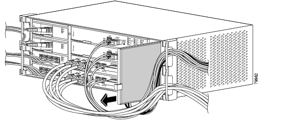
Figure 3-3 Removing the Reusable Fan-Tray Air Filter

Step 3 Visually inspect the filter material for dirt and dust.

Step 4 If the reusable air filter contains a concentration of dirt and dust, vacuum or wash the air filter. Prior to washing the air filter, replace the dirty air filter with a spare clean air filter (spare filters should be kept in stock).

Step 5 Wash the dirty air filter under a faucet with a light detergent. After washing the air filter, allow it to completely air dry for at least eight hours before reusing.


Note Cleaning should take place outside the operating environment to avoid releasing dirt and dust near the equipment.


Warning Do not put a damp filter back in the ONS 15327.


Step 6 Slide the clean air filter back into the shelf. (See Figure 3-4.)

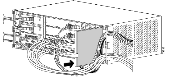
Figure 3-4 Replacing the Reusable Fan-Tray Air Filter


hometocprevnextglossaryfeedbacksearchhelp

Posted: Mon Feb 25 06:35:33 PST 2008
All contents are Copyright © 1992--2008 Cisco Systems, Inc. All rights reserved.
Important Notices and Privacy Statement.