|
|

Table Of Contents
4.2 ONS 15327 IP Addressing Scenarios
4.2.1 Scenario 1: CTC and ONS 15327s on Same Subnet
4.2.2 Scenario 2: CTC and ONS 15327s Connected to Router
4.2.3 Scenario 3: Using Proxy ARP to Enable an ONS 15327 Gateway
4.2.4 Scenario 4: Default Gateway on CTC Computer
4.2.5 Scenario 5: Using Static Routes to Connect to LANs
4.2.7 Scenario 7: Provisioning the ONS 15327 Proxy Server
IP Networking
This chapter explains how to set up Cisco ONS 15327s in internet protocol (IP) networks and includes:
•
Scenarios showing Cisco ONS 15327s in common IP network configurations
•
•
The chapter does not provide a comprehensive explanation of IP networking concepts and procedures.
Note
4.1 IP Networking Overview
ONS 15327s can be connected in many different ways within an IP environment:
•
•
•
•
•
•
4.2 ONS 15327 IP Addressing Scenarios
ONS 15327 IP addressing generally has seven common scenarios or configurations. Use the scenarios as building blocks for more complex network configurations. Table 4-1 provides a general list of items to check when setting up ONS 15327s in IP networks. Additional procedures for troubleshooting Ethernet connections and IP networks are provided in Chapter 9, "Ethernet Operation."
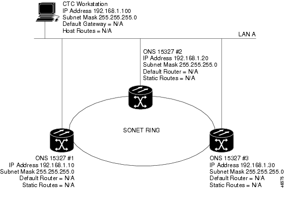
4.2.1 Scenario 1: CTC and ONS 15327s on Same Subnet
Scenario 1 shows a basic ONS 15327 LAN configuration ( Figure 4-1). The ONS 15327s and CTC computer reside on the same subnet. All ONS 15327s connect to LAN A, and all ONS 15327s have DCC connections.
Figure 4-1 Scenario 1: CTC and ONS 15327s on same subnet
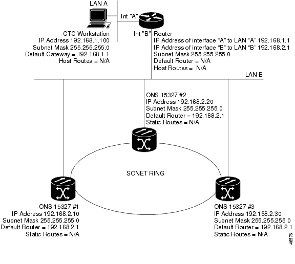
4.2.2 Scenario 2: CTC and ONS 15327s Connected to Router
In Scenario 2 the CTC computer resides on a subnet (192.168.1.0) and attaches to LAN A ( Figure 4-2). The ONS 15327s reside on a different subnet (192.168.2.0) and attach to LAN B. A router connects LAN A to LAN B. The IP address of router interface A is set to LAN A (192.168.1.1), and the IP address of router interface B is set to LAN B (192.168.2.1).
On the CTC computer, the default gateway is set to router interface A. If the LAN uses DHCP (Dynamic Host Configuration Protocol), the default gateway and IP address are assigned automatically. In the Figure 4-2 example, a DHCP server is not available.
Figure 4-2 Scenario 2: CTC and ONS 15327s connected to router
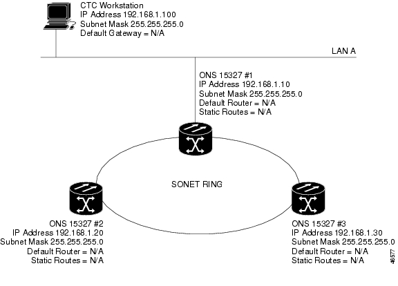
4.2.3 Scenario 3: Using Proxy ARP to Enable an ONS 15327 Gateway
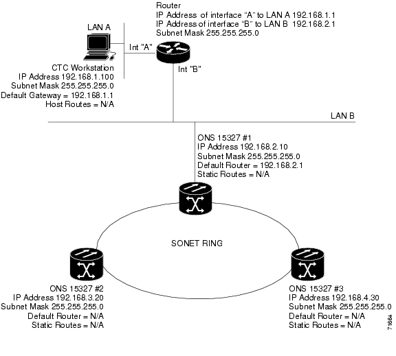
Scenario 3 is similar to Scenario 1, but only one ONS 15327 (node #1) connects to the LAN ( Figure 4-3). Two ONS 15327s (#2 and #3) connect to ONS 15327 #1 through the SONET DCC. Because all three ONS 15327s are on the same subnet, Proxy ARP enables ONS 15327 #1 to serve as a gateway for ONS 15327s #2 and #3.
Figure 4-3 Scenario 3: Using Proxy ARP
ARP matches higher-level IP addresses to the physical addresses of the destination host. It uses a lookup table (called ARP cache) to perform the translation. When the address is not found in the ARP cache, a broadcast is sent out on the network with a special format called the ARP request. If one of the machines on the network recognizes its own IP address in the request, it sends an ARP reply back to the requesting host. The reply contains the physical hardware address of the receiving host. The requesting host stores this address in its ARP cache so that all subsequent datagrams (packets) to this destination IP address can be translated to a physical address.
Proxy ARP enables one LAN-connected ONS 15327 to respond to the ARP request for ONS 15327s not connected to the LAN. (ONS 15327 Proxy ARP requires no user configuration.) For this to occur, the DCC-connected ONS 15327s must reside on the same subnet. When a LAN device sends an ARP request to an ONS 15327 that is not connected to the LAN, the gateway ONS 15327 returns its MAC address to the LAN device. The LAN device then sends the datagram for the remote ONS 15327 to the MAC address of the proxy ONS 15327. The proxy ONS 15327 uses its routing table to forward the datagram to the non-LAN ONS 15327.
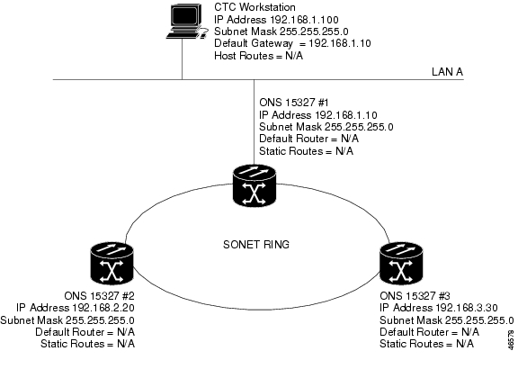
4.2.4 Scenario 4: Default Gateway on CTC Computer
Scenario 4 is similar to Scenario 3, but nodes #2 and #3 reside on different subnets, 192.168.2.0 and 192.168.3.0, respectively ( Figure 4-4). Node #1 and the CTC computer are on subnet 192.168.1.0. Proxy ARP is not used because the network includes different subnets. In order for the CTC computer to communicate with ONS 15327s #2 and #3, ONS 15327 #1 is entered as the default gateway on the CTC computer.
Figure 4-4 Scenario 4: Default gateway on a CTC computer
4.2.5 Scenario 5: Using Static Routes to Connect to LANs
Static routes are used for two purposes:
•
•
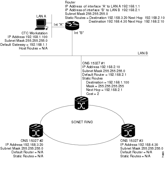
In Figure 4-5, one CTC residing on subnet 192.168.1.0 connects to a router through interface A. (The router is not set up with OSPF.) ONS 15327s residing on subnet 192.168.2.0 are connected through ONS 15327 #1 to the router through interface B. Proxy ARP enables ONS 15327 #1 as a gateway for ONS 15327s #2 and #3. To connect to CTC computers on LAN A, a static route is created on ONS 15327 #1.
Figure 4-5 Scenario 5: Static route with one CTC computer used as a destination
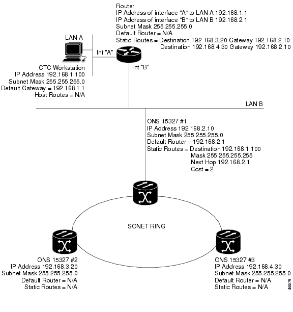
The destination and subnet mask entries control access to the ONS 15327s:
•
•
•
The IP address of router interface B is entered as the next hop, and the cost (number of hops from source to destination) is 2.
Figure 4-6 Scenario 5: Static route with multiple LAN destinations
4.2.6 Scenario 6: Using OSPF
Open Shortest Path First (OSPF) is a link state Internet routing protocol. Link state protocols use a "hello protocol" to monitor their links with adjacent routers and to test the status of their links to their neighbors. Link state protocols advertise their directly-connected networks and their active links. Each link state router captures the link state "advertisements" and puts them together to create a topology of the entire network or area. From this database, the router calculates a routing table by constructing a shortest path tree. Routes are continuously recalculated to capture ongoing topology changes.
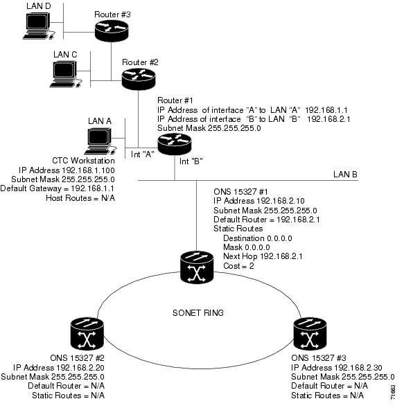
ONS 15327s use the OSPF protocol in internal ONS 15327 networks for node discovery, circuit routing, and node management. You can enable OSPF on the ONS 15327s so that the ONS 15327 topology is sent to OSPF routers on a LAN. Advertising the ONS 15327 network topology to LAN routers eliminates the need to manually enter static routes for ONS 15327 subnetworks. Figure 4-7 shows the same network enabled for OSPF. Figure 4-8 shows the same network without OSPF. Static routes must be manually added to the router in order for CTC computers on LAN A to communicate with ONS 15327 #2 and #3 because these nodes reside on different subnets.
OSPF divides networks into smaller regions, called areas. An area is a collection of networked end systems, routers, and transmission facilities organized by traffic patterns. Each OSPF area has a unique ID number, known as the area ID, that can range from 0 to 4,294,967,295. Every OSPF network has one backbone area called "area 0." All other OSPF areas must connect to area 0.
When you enable ONS 15327 OSPF topology for advertising to an OSPF network, you must assign an OSPF area ID to the ONS 15327 network. Coordinate the area ID number assignment with your LAN administrator. In general, all DCC-connected ONS 15327s are assigned the same OSPF area ID.
Figure 4-7 Scenario 6: OSPF enabled
Figure 4-8 Scenario 6: OSPF not enabled
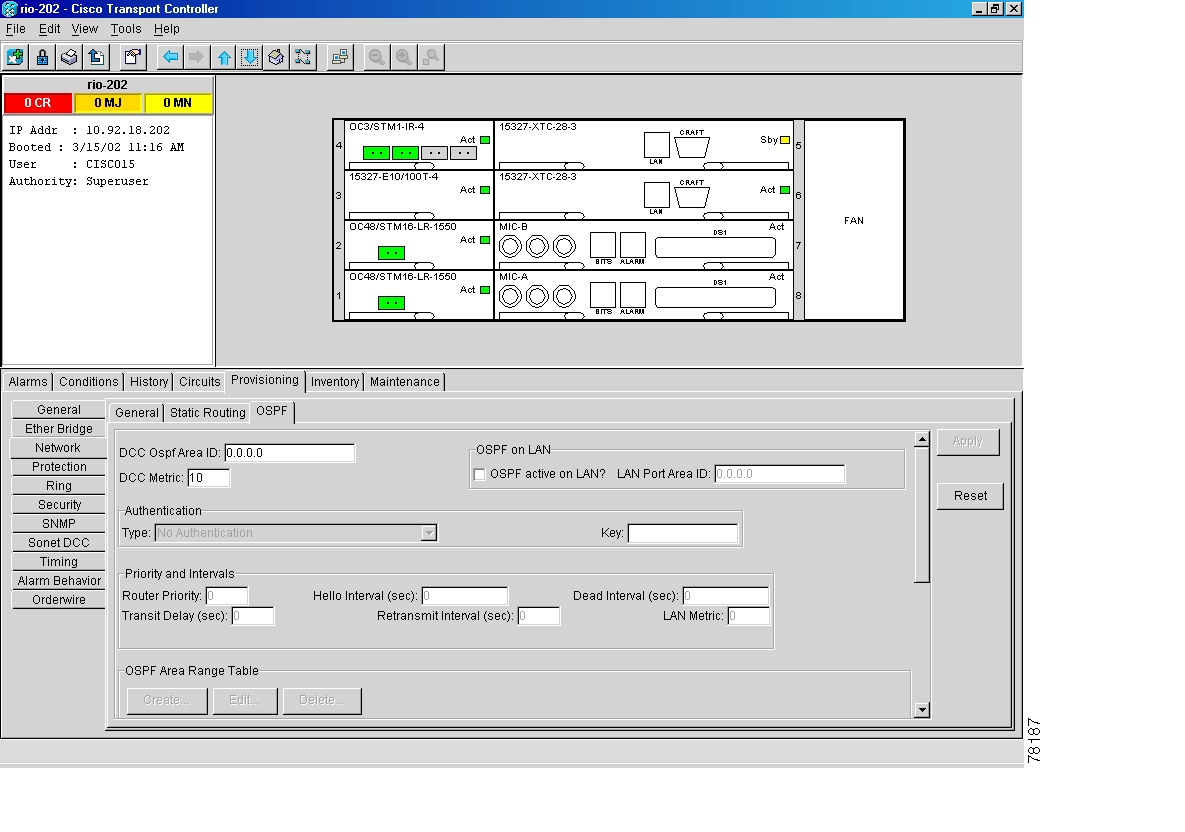
Use the following procedure to enable OSPF on each ONS 15327 node that you want included in the OSPF network topology. ONS 15327 OSPF settings must match router OSPF settings, so you will need to get the OSPF Area ID, Hello and Dead intervals, and authentication key (if OSPF authentication is enabled) from the router to which the ONS 15327 network is connected before enabling OSPF.
Procedure: Set Up OSPF
Step 1
Step 2
Figure 4-9 Enabling OSPF on the ONS 15327
Step 3
•
•
Step 4
•
•
Step 5
•
•
Step 6
The OSPF priority and intervals default to values most commonly used by OSPF routers. In the Priority and Intervals area, verify that these values match those used by the OSPF router where the ONS 15327 is connected.
•
•
•
•
•
•
Step 7
Note
a.
b.
–
–
–
–
c.
Step 8
a.
b.
•
•
•
•
•
•
c.
Step 9
If you changed the Area ID, the XTC cards will reset, one at a time. The reset will take approximately 10-15 minutes.
4.2.7 Scenario 7: Provisioning the ONS 15327 Proxy Server
The ONS 15327 proxy server is a set of functions that allows you to network ONS 15327s in environments where visibility and accessibility between ONS 15327s and CTC computers must be restricted. For example, you can set up a network so that field technicians and network operating center (NOC) personnel can both access the same ONS 15327s while preventing direct access between the field and the NOC LAN. To do this, one ONS 15327 is provisioned as a gateway NE (GNE) and the other ONS 15327s are provisioned as element NEs (ENEs). The GNE ONS 15327 tunnels connections between a CTC computers and ENE ONS 15327s, providing management capability while preventing access for non-ONS 15327 management purposes.
The ONS 15327 proxy server performs the following tasks:
•
•
•
•
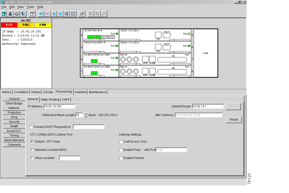
The ONS 15327 proxy server is provisioned using three checkboxes on the Provisioning > Network > General tab (see Figure 4-10):
•
•
•
Figure 4-10 Scenario 7: Proxy Server Gateway Settings
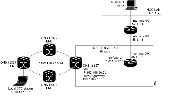
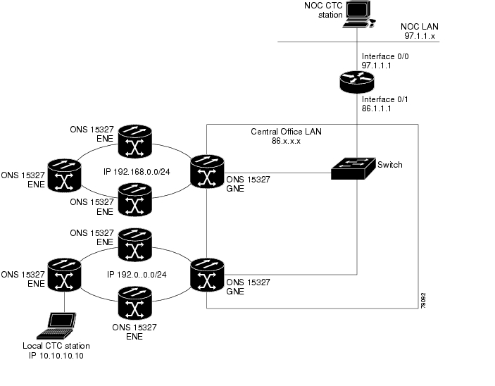
Figure 4-11 shows an ONS 15327 proxy server implementation. A GNE ONS 15327 is connected to a central office LAN and to ENE ONS 15327s. The central office LAN is connected to a NOC LAN, which has CTC computers. The NOC CTC computer and craft technicians must both be able to access the ONS 15327 ENEs. However, the craft technicians must be prevented from accessing or seeing the NOC or central office LANs.
In the example, the ONS 15327 GNE is assigned an IP address within the central office LAN and is physically connected to the LAN through its LAN port. ONS 15327 ENEs are assigned IP addresses that are outside the central office LAN and given private network IP addresses. If the ONS 15327 ENEs are co-located, the craft LAN ports could be connected to a hub. However, the hub should have no other network connections.
Figure 4-11 Scenario 7: ONS 15327 Proxy Server with GNE and ENEs on the same subnet
Table 4-2 shows recommended settings for ONS 15327 GNEs and ENEs in the configuration shown in Figure 4-11.
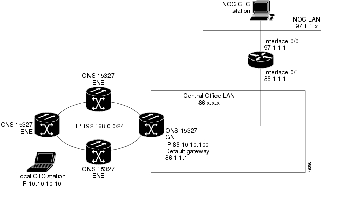
Figure 4-12 shows the same proxy server implementation with ONS 15327 ENEs on different subnets. Figure 4-13 shows the implementation with ONS 15327 ENEs in multiple rings. In each example, ONS 15327 GNEs and ENEs are provisioned with the settings shown in Table 4-2.
Figure 4-12 Scenario 7: ONS 15327 Proxy Server with GNE and ENEs on different subnets
Figure 4-13 Scenario 7: ONS 15327 Proxy Server with ENEs on multiple rings
Table 4-3 shows the rules the ONS 15327 follows to filter packets when Enable Firewall is enabled. If the packet is addressed to the ONS 15327, additional rules, shown in Table 4-4, are applied. Rejected packets are silently discarded.
If you implement the proxy server scenario, keep the following rules in mind:
•
•
•
•
•
If nodes become unreachable in cases 1, 2 and 3, you can correct the setting by performing one of the following:
•
•
4.3 ONS 15327 Routing Table
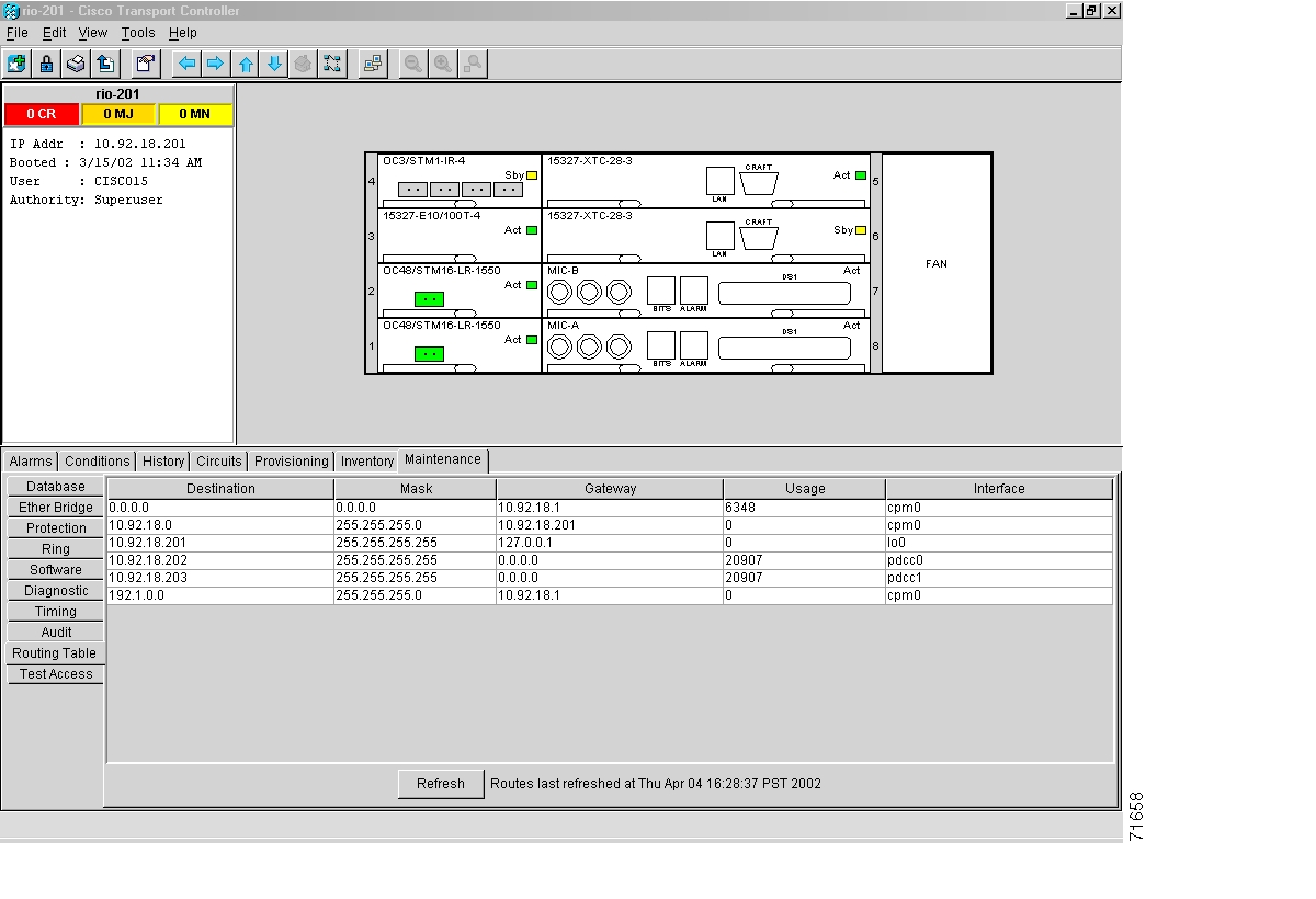
ONS 15327 routing information is displayed on the Maintenance > Routing Table tabs ( Figure 4-14). The routing table provides the following information:
•
•
•
•
•
–
–
–
Figure 4-14 Viewing the ONS 15327 routing table
Table 4-5 shows sample routing entries for an ONS 15327.
Entry #1 shows the following:
•
•
•
•
Entry #2 shows the following:
•
•
•
•
Entry #3 shows the following:
•
•
•
•
Entry #4 shows the following:
•
•
•
•
Entry #5 shows a DCC-connected node that is accessible through a node that is not directly connected:
•
•
•
•
![]()
![]()
![]()
![]()
![]()
![]()
![]()
![]()
Posted: Mon Feb 25 06:01:01 PST 2008
All contents are Copyright © 1992--2008 Cisco Systems, Inc. All rights reserved.
Important Notices and Privacy Statement.